

Page 1
PIN 990450
Commodore
Graphic Printer
Technical
Manual
Model
1515/1525
Manual
e::
commodore
COMPUTER
Page 2

These documents are for repair service information only. Part numbers are
for
reference
only. Only parts on current dealer parts list are available. No license
is
given
for
any use by
possession of these documents and may not
be
reproduced
in
any form
withoutthe
written
approval
of
Commodore Electronics Limited.
Page 3
CONTENTS
I.
SPECI
FICATIONS
..........................................................................................................................
2
II. CONSTRUCTION
............................................................................................................................
5
1.
SUMMARY ................................................................................................................................. 5
2.
PRINTING ................................................................................................................................. 7
3.
LIN8FEED ................................................................................................................................
10
4.
CIRCUIT .....................................................................................................................................
12
5.
TIMING DIAGRAM ...................................................................................................................
14
III.
REPAIRING LEVEL
.....................................................................................................................
17
IV. MEASURING INSTRUMENTS AND TOOLS
........................................................................
17
V. MAINTENANCE
.............................................................................................................................
18
1.
CLEANING ................................................................................................................................ 18
2.
LUBRICATING ........................................................................................................................... 18
VI.
DISASSEMBLY AND REASSEMBLY
.......................................................................................
19
1.
UPPER
CASE
............................................................................................................................. 19
2.
LOWER
CASE
BLOCK AND MACHINE ASSEMBLy ..............................................................
20
3.
LOWER
CASE
BLOCK ..............................................................................................................
23
4.
CONTROL
PCB
UNIT AND LAMP
PCB
UNIT
........................................................................
26
5. PRINT HEAD
UNIT
..................................................................................................................
27
6.
LINEFEED MECHANISM ..........................................................................................................
28
7.
FEED DRUM AND CARRIER
UNIT
.......................................................................................
29
8.
GEAR TRAIN ................................................................................................................. ,..........
32
9.
TRACTOR ........................................................................................................................ ..........
34
VII.
TROUBLESHOOTING.................................................................................................................... 35
1
Page 4
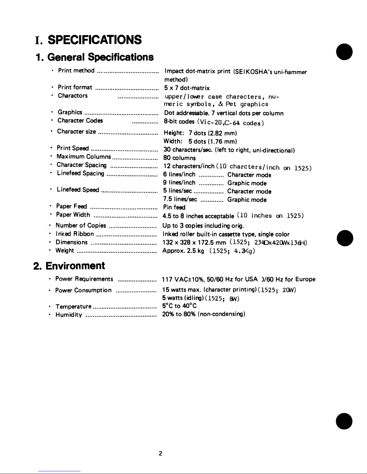
I.
SPECIFICATIONS
1. General Specifications
• Print method ................................... Impact dot-matrix print
(SEI
KOSHA's uni-liammer
method)
• Print format .................................... 5 x 7 dot-matrix
• Charactors
• Graphics .•........................................
• Character
Codes
• Character
size
................................. .
upper/lower
case
characters,
nu-
rreric
s~ols,
&
Pet
graphics
Dot
addressable.
7 vertical dots per column
8-bit
codes
(Vi
c-20
,C-64
codes)
Height: 7 dots (2.82 mm)
Width: 5 dots (1.76 mm)
• Print
Speed
.............................. ........ 30 characters/sec. (left
to
right, uni-d irectional)
• Maximum Columns .......................... 80 columns
• Character Spacing ........................... 12 characters/inch
(10
charcters/
inch
on
1525)
• linefeed Spacing ............................. 6 lines/inch .............. Character mode
9 lines/inch .............. Graphic mode
• linefeed
Speed
................................ 5 lines/sec ................. Character mode
7.5 lines/sec ............. Graphic mode
•
Paper
Feed
...................................... Pin
feed
•
Paper
Width . ........... ........................ 4.5
to
8 inches acceptable
(10
inches
on
1525)
• Number
of
Copies ........................... Up
to
3 copies including orig.
• Inked Ribbon .................................. Inked roller built-in
cassette
type, single color
• Dimensions ..................................... 132 x 328 x 172.5 mm
(1525;
23LOx420Nx13lH)
• Weight ............................................. Approx. 2.5
kg
(1525;
4.:3<g)
2. Environment
• Power Requirements
• Power Consumption ...................... .
• Temperature .................................... .
• Humidity ....................................... .
117 VAC±'IO%,
50/60 Hz
for
USA )/60
Hz
for
Europe
15 watts max. (character printing)
(1525;
200)
5 watts (idling)
(1525;
BN)
5°C
to
4Q°C
20%
to
80% (non-condensing)
2
Page 5
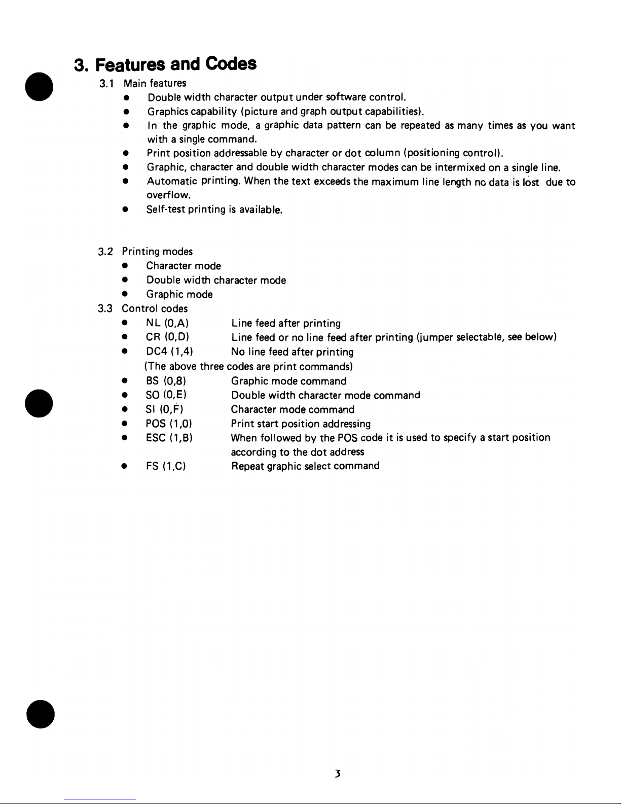
3.
Features
and
Codes
3.1
Main features
• Double width character
output
under software control.
• Graphics capability (picture
and
graph output capabilities).
• In the graphic mode, a graphic
data
pattern
can
be
repeated
as
many times
as
you want
with a single command.
• Print position
addressable
by character or
dot
column (positioning control).
• Graphic, character
and
double width character
modes
can
be intermixed on a single line.
• Automatic printing.
When
the
text
exceeds
the maximum line length
no
data
is
lost due
to
overflow.
• Self-test printing
is
available.
3.2 Printing
modes
• Character mode
• Double width character mode
• Graphic mode
3.3 Control
codes
• N L (O,A) Line
feed
after printing
•
CR
(0,0) Line
feed
or
no
line
feed
after printing (jumper selectable,
see
below)
• DC4 (1,4) No line feed after printing
(The
above
three
codes
are
print
commands)
•
BS
(0,8) Graphic mode command
•
SO
(O,E) Double width character mode command
•
SI
(O,F)
Character mode command
•
pas
(1,0) Print start position
addressing
•
ESC
(l,B)
When
followed by the
pas
code
it
is
used
to
specify a start position
according
to
the
dot
address
•
FS
(l,C)
Repeat
graphic select command
3
Page 6
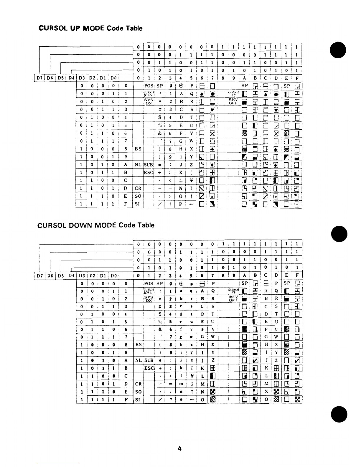
CURSOl
UP MODE Code Table
0
010
0 0 ! 0
I 0 I
0 1
,
1
I
1
I
1 , 1
I
1 !
1 I 1
, .
I
I
-----+-
0
01
0
I
0 1
I
1 I 1
I
1
0 0
I
0
i
o
II!
1 I
1 I
1
i
I
i
0
0
I
1
I
1 0 I 0
I
1 !
1 0 0
I
1 i 1
!
0
i
0
I
III
I
0 I 1 I 0
I
1 0 i 1
,
0 I 1 0 1
,
0
1
I 0
I
1
!
0
I
1
I
,
I
,
l
07 I 06
I
D51
04 I 03 : 02 i 01 . DO
i
I
0
;
1
:
2 I
3
I
4
I
5
I
6
,
7
8 9 A
B
,
C
0
E
:
F
,
,
0 i 0
,
0 i 0
I
0
POS;
SP:
IJ
I
@i
PiE
0:
SP
~ ,
:'
. 0 '
sP:
[21
,
i 0
0
0
i
1 , 1
(IN'~
·
I
1
I
A
,
Q '
.,
~
l,0:':
[J
:x::
•
•
[J
a:i
,
,
(ll'\~',
I
I,;'
I
I
0 ; 0
1
i
0 2
svs
·
2
I
B
R .
r;
n
REV
~
-,
I
II
.~
I
O~
, , ,
"""
OFF
•
I
...
I
0 0 1 1 3
;
3
r
C
S.
~
~
:r
••
"-:1:
,
-,
,
,
!
I!
~
I
,
I
I
T:
~
0:
::J
C r--.Il
=._U
~
0 1
0
0
4
S i
4
D,
I 0
,
1 , 0 , 1
,
5
I
t}o
:
5
I
E
U!LJ'Ld
C_t=
C
:2
o [:
I 0
,
1
1
0 i 6
I
!
&!
6
I
F
v·
Q
~'
I
]
;-
~
~
CL
,
;
~
i
1 I 1 i 1
I
7
j
1~~WiIJ
u~~L:fn
c
l:l
u~[Ji
I
1
i
0
,
0 I 0
I
8 BS
:(18
HIX![]
~!
m -
[]
~.;Di
I
I
,
I ~ :
r:]i-.
t;
1 I 0 I 0
I
1
I
9
,
I
9 I
,
Y
n'r:
[]r"!
I
)
I
-~,
:
..
,
1
o j
1 i 0 !
A
NL
SLll:
•
J I
z
I~!~i
:0
o :
~
,
'+l
! 0
;]1
1
I
o I
1 )
1
I
B
ESCj
+
;
I
KI
[ I
~
I
Eli
i
.
ICE
1J';r
a:J:
[]
,
L!
!
L.J
I,'
I
1
1
I
0
I
0
I
C
I
<
LI
T 1
0
:
(]
I
,
:[1
~'CIJ![i:"1
I
I,
,
I'
1 j 0
;[5
,
m~
1
I
1
I
D
CR
,
-I
=
N
) i
~!~!
0]1
"::11'
,
i
,-i
1 S
,OJ
[5
I
L!~
I
1
i
1
I
1
i
0 I
E SO
I I
)
O!
,il
~i:ZGlI!:L'1Il1
,
I
T : 0 i
If
I " •
1r
I,
,
/1
I
.-o:~:
-i
I
1 ! 1 i 1
!
1 F
51
:
,
p:
Ii
!iI
,[
~:
r , ,-.
,
I • :
-
-
~i
-
CURSOL
DOWN
MODE
Code Table
0
I
0 I 0 0 j
0 0
0
I
o t
1
1
i
1
I
1
I
1
I
1 1
,
1
1
i
,
,
01
0
I
I
I
I
!
I
0
0
I
1
1
1
1
I
0
,
0 0 0
I
1
1
,
1
0
I
0
i
1
1
,
0 0 1
1
i
0
i
0
1 1
I
01
0
1
I
1
I
I
I
I
i
,
I
,
,
0
1 0
1 0 1 ! 0
1 I 0
,
1
0 1
011
o I
1
I
,
I
I
07 i 06 I 05 i 04
03 : 02 : 01 : 00
I
It
1
I
2
3
I
4
5
,
7 I I
i
9
A 8
:
C
I
0 E
I
F
,
,
0 I 0
0
i
o I
0
,POS·
SP
II
I
(!.
p
.6:
pi
I
SP'
Gi
P
SP:
[2
,
0
I
0 0 ! 1
I
1
tYR;:".
,
1
I
•
II
:
A
I
QI
':l,~~,
[J
L
~
~
A
!
Q i
[]
;:I; i
;VJ~
~
,
,
L........i
I
0 i
0
1 0
i
2
svs
~
2
I
b
r
B!
R
It
..
:v"'--r-~~
B
!
R
I.
"
;
!
0:-;'
OFF
.~tr_
.
::r:
'
0
i
0
1
1 I
3
I
I
;:
3
,
c $
c
I
5
LO~,
E[
c
s
IO;:i
I
I
~
0
1 0 0
I
4
,
si
4 d
t
Oi
T
'DO:
Dr
TiO,D
,
0 1
0
1 S
90
I
5
~
u
E
I
t'
.
10
[JI
E
i
u
10
[J'
;
0 1 1
0
6
,
lJ,;
6
f
\-
t-
\.
I
1.,
[]
i
F
I
V
EiJ
I
,
i
,
:
~
1
v;
i
DID!
Gjw
DiU:
0
,
1 1 1
i
7
I
' ,
7
,
c
,..
G
,
I
i
,
~
!
ii
I u I
I
1
0
0
0
8
BS:
1
(
I
•
,
h
It
H
I X i
i
HIX
m~
I
,
,
,
1
I
0
0 1 9
)
9
I
i
I
).
!
I
yl
i
~I~!
' I
f&'
~
,
I
10
lal
I : Y , • :
1
1
•
1
0
A
:\L
:5Lll
•
j
)
z
I
J
Z
liZ
D:.ai
1
I
0
!
1
,
1
1
B
:ESCI
+
k I
[
I K
iii
~
[E
lJ
KIE8
[]:iJJ
I
; ,
1 1
i
0 0
c
<
J
,
¥I
L
(]i
:
[J
~
L
II]
[il~i
·
I
i
-
J
l M
[]i
rs
E!l
~I
I []
[!jitJi
I 1
,
0
i
1
0
CR
-
=
mi
I
,
1 1 1
I
•
E
50
)
•
!
T
,
N
g'
I
@
~
~!~IEili[]!
;
I
i
1 1 I 1
I
1 F SI
/
•
0
!
.-1
0
~i
i
IlJ!~
OI~ICJI~'
,
4
Page 7
II.
CONSTRUCTION
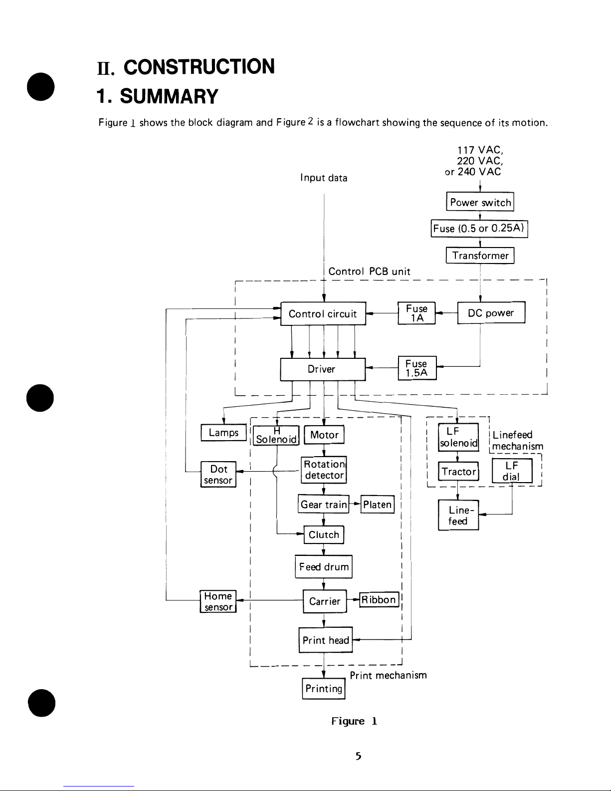
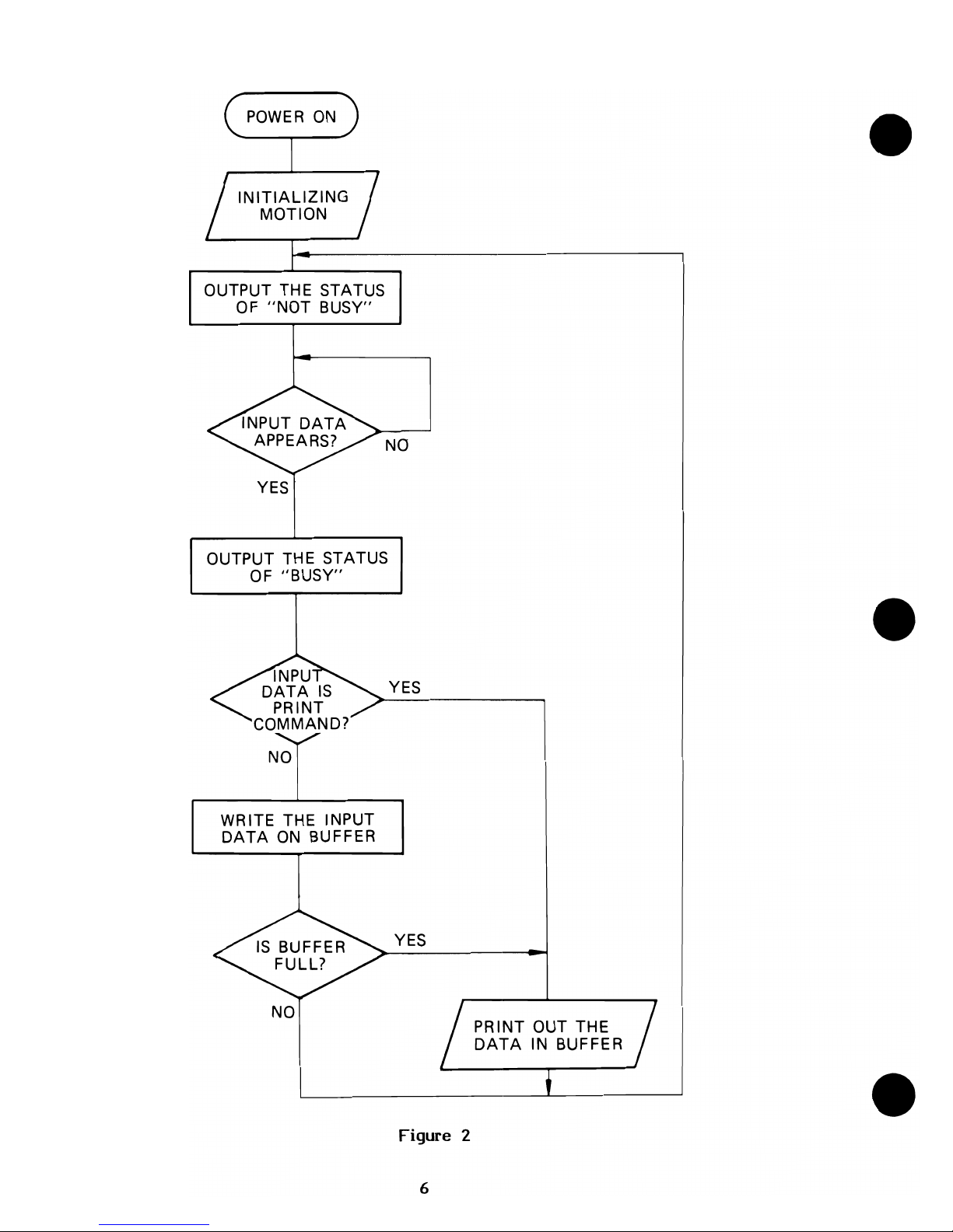
1. SUMMARY
Figure 1 shows the block diagram and Figure 2
is a flowchart
showing the sequence
of
its
motion.
I
nput
data
Control
PCB
unit
,--------
I
I
I
I
I
I
L
__
_
.---L..-..... Print mechanism
Figure 1
5
117VAC,
220 VAC,
or
240
VAC
I
I
-
-1-
- - -
-I
I
I
I
I
I
I
I
_______
J
Line-
'--_---'
feed
Page 8
OUTPUT THE STATUS
OF
"NOT
BUSY"
NO
YES
OUTPUT THE STATUS
OF
"BUSY"
NO
WRITE THE INPUT
DATA
ON
BUFFER
NO
YES
YES
Figure 2
6
PRINT OUT THE
DATA
IN BUFFER
Page 9
2.
PRINTING
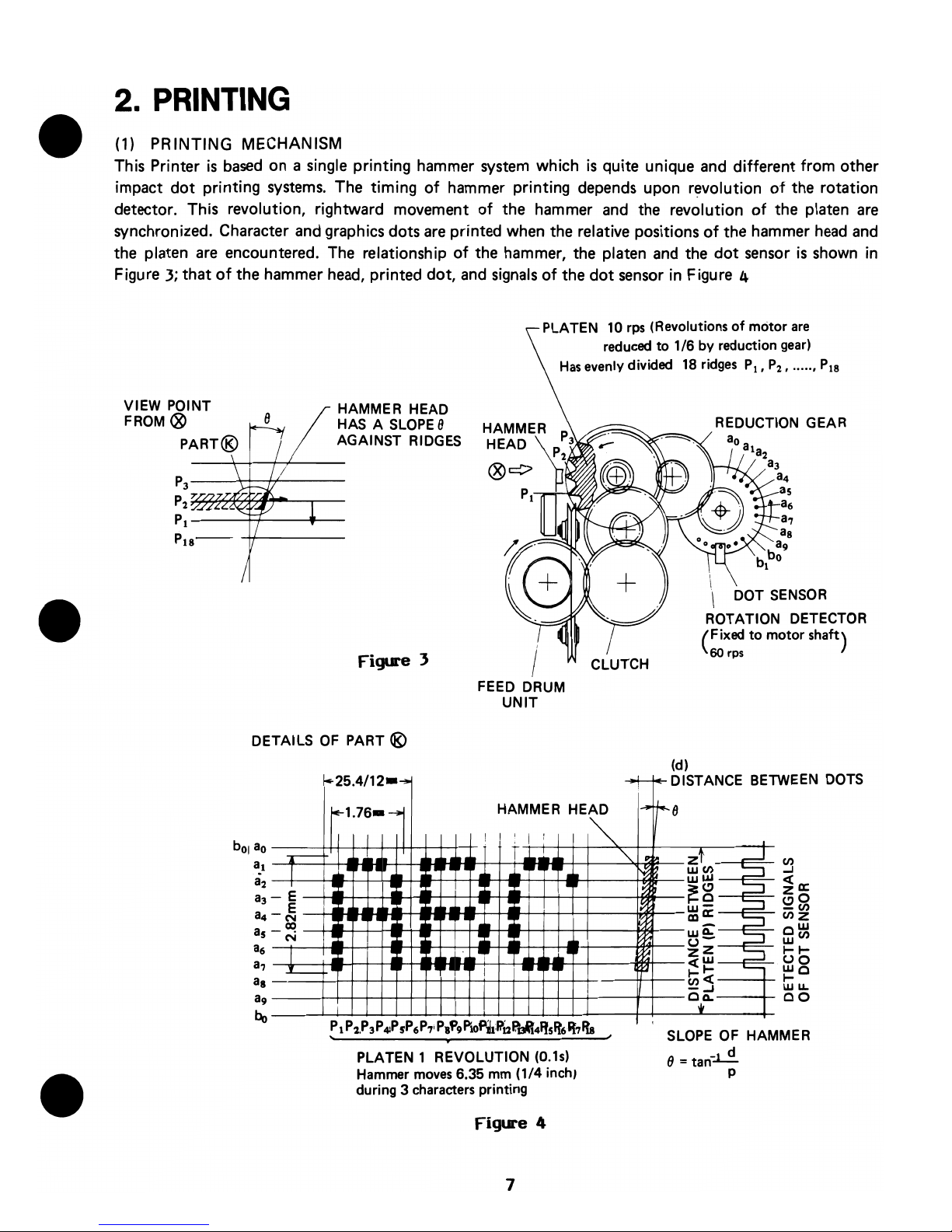
(1) PRINTING MECHANISM
This Printer
is
based
on a single
printing
hammer system which
is
quite unique and
different
from
other
impact
dot
printing systems. The timing
of
hammer printing depends upon revolution
of
the rotation
detector. This revolution, rightward movement
of
the hammer and the revolution
of
the platen
are
synchronized. Character and graphics dots
are
printed when the relative positions
of
the hammer head
and
the platen
are
encountered. The relationship
of
the hammer, the platen and the
dot
sensor
is
shown
in
Figure
3;
that
of
the hammer head, printed
dot,
and signals
of
the
dot
sensor in Figure 4
VIEW POINT
FROM®
PART®
HAMMER HEAD
HAS A
SLOPE
8
AGAINST RIDGES
P
3
---4-+-+f----
P
2
B7~~~~",---,----
PI---~--~-
/
Figure 3
DETAI
LS
OF
PART ®
..
25.4/12-...,.
b
OI
ao
a
..
a2
a3
a4
as
a6
a7
a8
a9
bo
.----
I
-E
E
-N
m
-
N
I
~
l
I
I
I
iE-l.76
__
I.
,.
,.
--II"
~
~.
". ".
ii~
~
I
II
PLATEN 10
rps
(Revolutions
of
motor
are
reduced
to 1/6
by
reduction
gear)
Has
evenly divided
18
ridges
PI,
P
2
, ••••• ,
P
I8
FEED DRUM
UNIT
CLUTCH
(d)
REDUCTION GEAR
ROTATION DETECTOR
(
Fixed
to
motor shaft)
60 rps
-+-1+- DISTANCE
BE
TWEEN
DOTS
!
~AMIM~R
HE1~
,-1-8
T
I.,
"-
zt
-1
N
wen
~
Ww
•
I
~
~g
;::::J
I~
;::::J
w-
.~
ma::
~
wei:'
'"""=l
u-
ZZ
;::::::J
c(w
I
.".
,.
1-1-
'---
enc(
-...I
c,*Q.
PLATEN 1 REVOLUTION (O.ls)
Hammer
moves
6.35 mm (1/4 inch,
during 3 characters printing
SLOPE
OF
HAMMER
8
=tan~
p
7
Page 10
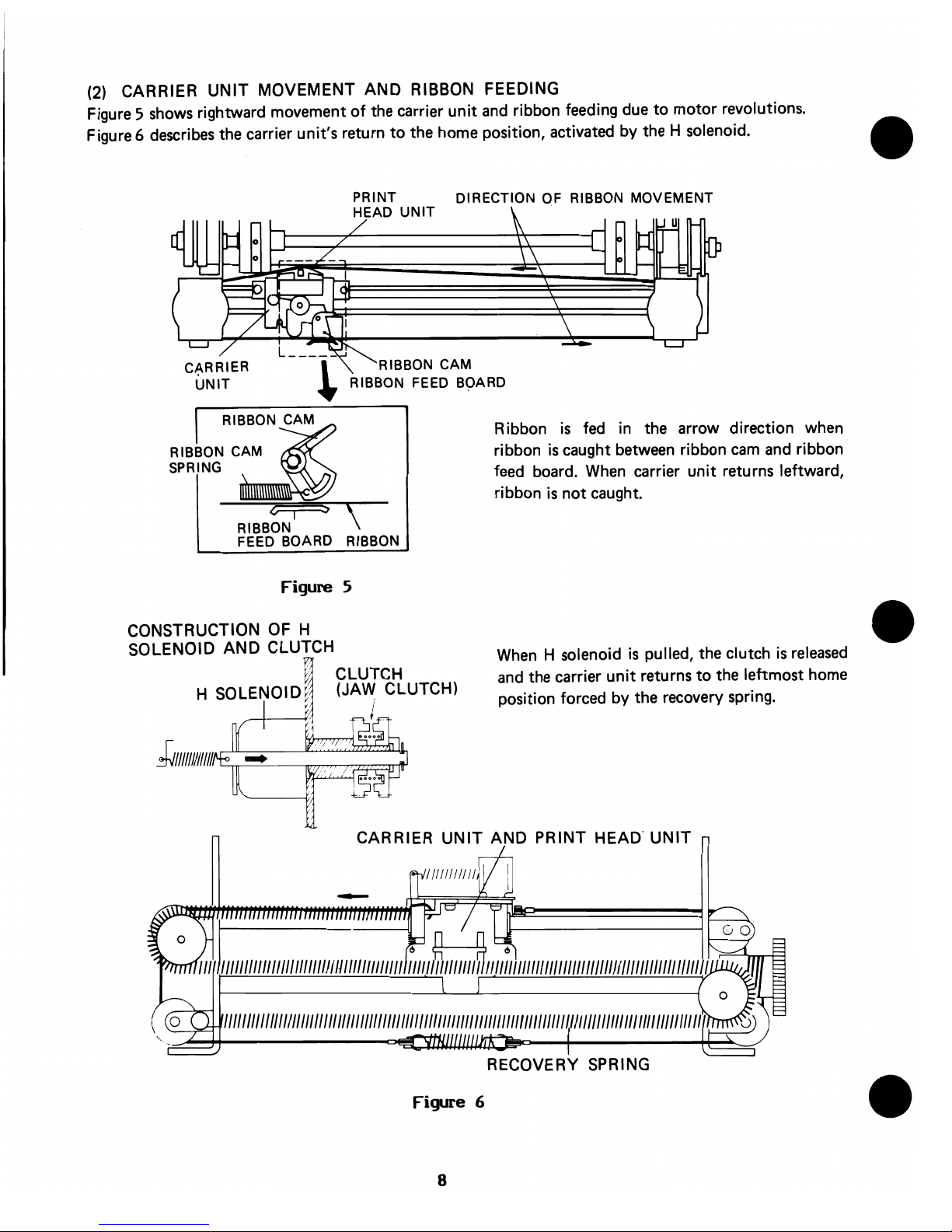
(2)
CARRIER
UNIT
MOVEMENT AND RIBBON FEEDING
Figure 5
shows
rightward movement
of
the carrier
unit
and
ribbon feeding due
to
motor revolutions.
Figure 6
describes
the carrier unit's return
to
the home position, activated by the H solenoid.
PRINT DIRECTION OF RIBBON MOVEMENT
HEAD
UNIT
RIBBON CAM
RIBBON FEED BOARD
RIBBON CAM
R'::tt
Ribbon
is
fed
in
the arrow direction when
ribbon
is
caught between ribbon
cam
and
ribbon
feed
board.
When
carrier
unit
returns leftward,
ribbon
is
not caught.
SPRING
RIBB~NI
~
\
FEED BOARD RIBBON
Figure
5
CONSTRUCTION
OF
H
SOLENOID AND CLUTCH
m CLUTCH
H SOLENOID;l (JAW CLUTCH)
'j
,
---J<1 / .
! ,
When
H solenoid
is
pulled, the clutch
is
released
and
the carrier
unit
returns
to
the leftmost home
position forced by the recovery spring.
CARRIER
UNIT
AND PRINT HEAD'
UNIT
1/1/1111
//11
1111/111
1/1"
11//11/11/""
1111/11111111111111111111111111
IIlIllIllllIIl/lIIlII
1/111/111
1111/
, ---'---------'
RECOVERY SPRING
Figure 6
8
Page 11
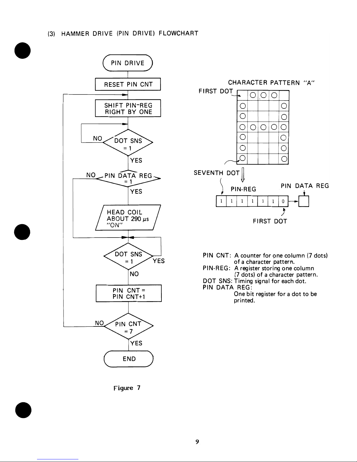
(3)
HAMMER DRIVE
(PIN
DRIVE) FLOWCHART
NO
RESET
PIN CNT
SHIFT PIN-REG
RIGHT BY
ONE
FIRST 0
CHARACTER PATTERN
"A"
OT
0
,0
0
-
~
0 0
0
0
0
0
0
0
0
0
0
0
0
r--'r'0
0
SEVENTH DOT
~
) PIN-REG
NO
PIN
DATA
REG
= 1
NO
YES
HEAD COIL
ABOUT
290
p.s
"ON"
PIN
CNT =
PIN
CNT+1
END
Figure 7
9
PIN
DATA
REG
IO~D
)
FIRST DOT
PIN CNT: A counter
for
pne column
(7
dots)
of
a character pattenl.
PIN-REG: A register storing one column
(7
dots)
of
a character pattern.
DOT
SNS:
Timing
signal
for
each
dot.
PIN
DATA
REG:
One
bit
register
for a dot
to
be
printed.
Page 12

3. LINEFEED
(1)
LlNEFEED
MECHANISM
Figure 8
shows
the linefeed (paper feed) controlled by the motion
of
the LF solenoid. The LF solenoid
is
activated three times
for
printing characters
and
two
times for printing graphics.
The transmission
sequence
of
a LF solenoid motion
is:
LF
r----
CLAW WHEEL
f--------
LF CLAW
f-------+
GEAR
f-------.
TRACTOR
I---
TRACTOR
SOLENOID
UNIT
WHEEL
PIN
SHAFT
The condition
of
the claw wheel
unit
when the LF solenoid
is
inactive
is:
i)
The claw wheel
unit
is
pulled
by
the LF rope spring.
iil
The
saw
teeth
of
the LF claw wheel and the
saw
teeth which
are
pushed
by
the claw wheel
spring
are
coupled.
REVERSE
STOP
CLAW
EARTH PLATE
(Ll
LF SOLENOID
LF
ROPE
CLAW LF CLAW EARTH
LF
CLAW
WHEEL STOPPER PLATE
(Ll
WHEEL
UNIT
.CLAW WHEEL SPRING
LF
ROPE
SPRING
LF SOLENOID
Figure 8
10
Page 13

(2)
LlNEFEED
FLOWCHART
LENEFEED
LFCNT = 3
LFCNT=
LFCNT
-1
YES
END
NO
LFCNT: COUNTS THE NUMBER
OF
LlNEFEED
k'~~~:/~Zb~G
I I I
II
r-
--~I_-_--_·~~S~~~~O'D"ON"
I
~
~
. LF SOLENOID
"OFF"
~
33ms
33
ms
Figure 9
11
Page 14
~
N
eN
I
ADDRESS/TEST
SWITCH
RAI-I
I
':~--------------T,~~~e
~~
CN2
0.1
~
RD
-
.::=il
Vc<°
[~W;;~?tJ
o..S7.)
ATNPJ A
..
_A
£If
W
Vee
I~RAH
Sfto.03
GND~
C3""'-
C8
Vee
11_-f
10H
II
.,JT
(NOTE)
Aa
A.
RESISTOR
VAlUES
ARE
IN
(kQ]
UNLESS
OTHERWISE
SPECIFIED.
CONDENSER
VALUES
ARE
IN
(PF]
UNLESS
OTHERWISE
SPECIFIED.
*1.*2
WITH
HEAT
SINK.
2732 -
CONNECT
J I •
J.
2332
-CONNECT
J2.
J3
'E=:
w
~~Ol~~~
*"~YE
-::;t
-
__
12~3
c2llRI~CN5-
Y .
........
(LS
I.)
10.Z
ll:2.2
L....L..!J~~
-'
L--I>lIP~
-'
~
a.
RI.
0.075
(2W>
)C~
RD
CN8
HEADa..umt
WH
I)
CN9
• • m
LF
WIItH
Gft
•
C7JY)E
CNIO
I t£ADaIl
vee-----<D~~L-
~
~OR~ERLA~
0.3
SlR~o
BlU
~
* J 1
0
;:
r
'0
1.2'
cn~u,
tt~)
..
I'
+
PA780SC
~~
+
1*
I
(6.~
__
_
D.
HZ6C2
CNIl
+>.1
• r.,...
lYE
••
J • ___
u'.
.
...
__
._..
,-----",)
CNI'
Figure
10
~
•
o
-
:l:J
o
c:
-
~
Page 15

~
'-I
LED~III
II
II
n,.IIII.
r~1I
II
___
PH
II
II-Orange
Jumper
White
1it-lJ
II
I~BlueJU-
Yellow
Red
II
1I11--White
Red
R7
II
IlcON'I/
II
R9
RA
..
C6
Ilbuuu
u~l'4
~'7
~
TP30
e:Eq)
~8
C19'
-~
....
o
,,"
~-~!~~f1~~'"';A;""1
~
cloIO~9ga~~aa~J
PI
P2
i~UUCI4
~R5
11000
oouou
'IRAI
RI7ce:::p
~
[::~:::]
C}::]
[:::~::]
05
E
1'-"-"-"-"-:~~o-"-"-"-"-'l~::](::'J:]
®f::
:~:~l
[;;;
;;ii:
;:;:
;;:;:
]Q,
[El]
CONI
R3
RA2
.rIIXI
=
11
6
ouuuuJf.2J~~~
• SWl : GP-SOA
only
Figure 11
w
-
n
g
....
.,
Q
-
C9
III
n
c
3
~
c
;:,
(1)
;::,
....
<
....
(1)
~
811~11~11
Q31111il1.JI.IIIIAIr'l1l
'o21111111.l11
111111
o
Page 16

5.
liMING
DIAGRAM
(1)
Initializing motion
'"
__
---------------------------------+5v
~---------------------OV
t
Vee
POWER
ON
~---------------------------+5V
RESET
(Pb/4~,.....,
I
____
J
--.I
about - - - -
~-
about
~
-----J
- I 66
ms
66
ms
I
HONE
(?I/I2.)
~
______
- __ - -
__
- - ___ I
Figure
12
When
power
is
applied,
or
the~signal
is
input
to'P2/l,2
[No.1
and
No.2
teriminals
of
IC
P2],
the
CPU
(P6/4)
accepts
the
RESET
signal,
the
CPU
is
reset
as
long
as
this
signal
is
LOW,
or
about
2V
or
less.
The
CPU
activates
as
soon
as
it
rises
from
LOW
to
HIGH.
First,
the
CPU
makes
the
HCsignal
(P8/9)
LOW
turning
on
the
drivers
(P7/l3,14).
When
they
are
on,
the H solenoid
is
~ved
to
the
head
carrier
return
to
the
home
positon
forced
by
the
recovery
spring.
The
HOME
signal
(Pl/12),
which
is
shaped
from
the
output
signal
of
the
home
sensor,
is
HIGE
the
head
carrier
is
at
the
home
position
and
is
LOW
when
out
of
the
home
posit1L~.
The
CPU
checks
the
HOME
signal
to
see
whether
it
is
HIGH
or
LOW.
If
it
18
HIGH,
the
CPU
will
~e
the
He
signal
HIGH
66
ms
later;
if
it
is
LOW.
the
CPU
waits
until
it
becomes
HIGH
and
66
.s
later
the
CPU
will
make
the
KG
signal
IIICH.
When
the
Hc
signal
becomes
HIGH
turning
the
drivers
(P7/l3,14)
OFF
(HIGH),
the
head
carrier
has
returned
to
the
home
position
with
completion
of
the H solenoid
motion.
Next
is
to
move
the
h~Jcarrier
to
the
aiddle
of
paper
and
back
to
the
home
posi
tion
in
order
to
check.
and
memoril,e
the
timing
of
rising
edge
of
the
HOME
signal
relatively
compared
with
the
DOT
signal.
This
timing
will
be
used
as
the
criterion
for
the
CPU
to
decide
when
to
start
printing.
With
the
abave
procedure,
the
printer
finishes
the
init~li
ing
motion
and
can
accept
input
data
from
this
moment.
Input
and
output
of
the
printer
are
conducted
through
VIC
ser_ial
bus.
14
Page 17

(2)
Start
of the printing motions
MOTOR
(pg/S") I
--f
about-----------------------------------------
160
ms
t--
He
(P8/9)
I
[
HOME (PI/IZ)
First dQt of Fiest
dot
of
dot
position 0
dot
position 1
j4--
5.56
ms---l
--..,;---
...... ~ ..
2 3 4 5 6 7 1 2 3 4
~OT
(P3/8)
nnnnnnn
nn
___
---<5fj~uuuu~~:
: : :
..
: : :
PI
N
(~P-S~/J-3
~)
---
580
Il
S
1.9
ms
----t'=t~~~~~
Figure
13
First column
of
pattern
"A"
\-
..
Second column
When
printing
starts,
the
CPU
makes
the
MOT
(P8/S)
andHC
signal
LOW.
Lowering
of
the
MOT
signal
makes
the
drivers
(P7/l5,16)
LOW
supplying
current
to
the
motor
to
race.
Since
the
H C
signal
is
also
LOW.
'the H solenoid
is
activated
to
relieve
the
motor
shaft
from
the
head
carrier
for
about
.160
ms
so
that
the
.ator
can
reach
constant
speed
of
revolution.
TheFfC
signal
is
raised
to
HIGH
engaging
the
motor
shaft
and
the
head
carrier
to
move
it
to
the
rightward
direction.
In
case
there
is
no
or
abnormal
output
from
the
dot
sensor,
the
CPU
turns
theHC
and
lUYr
signals
HIGH
and
halts
to
do
nothing
because
aechanical
error
must
have
occurred.
Next,
the
CPU
waits
and
sees
if
tho
printhead
leaves
the
home
position
via
the
HOME
signal
(Pl/12).
After
confirming
that
the
HOME
signal
becomes
LOW
which
means
the
head
carrier
gets
out
of
the
home
positi~."
the
CPU
goes
to
check
the
DOT
signal
(P3/8)
in
order
to
decide
when
to
start
printing.
The
DOT
signal
is a shaped
output
signal
of
the
dot
sensor
and a group
of
27
seruential
pulses
repeats
at a constant
interval.
The
rising
edge
of
the
DOT
signal
following
the
comparatively
long
duration
of
staying
LOW
(1.9
ms)
is
the
timing
to
start
printing.
When
this
signal
rises
from
LOW
to
HIGH
after
staying
LOW
for
.are
than
640~s,
the
CPU
takes
it
as
a'timing
to
start
printing
and
jumps
to
the
hammer
drive
routine.
In
case
of
printing
one
dot,
the
~lN
signal
(PB/13)
of
the
hammer
drive
pulse
which
is
synchronized
with
the
DOT
signal
is
made
LOW
for
about
290;Ms.
Lowering
of
t~e
PIN
signal
..
kes
the
driver
(P7/IO)
LOW,
turns
the
transistor
(Ql)
ON
and
drives
the
hammer. The
27
pulses
consist
of
three
7-dot
columns
as
shown
below.
15
Page 18

, U
>OO"'~>UI~)
(I/(,lJO)f!Ii~~1t!')
Z.J
fJ'1""
""4/~~~"'7/"'.~'O»~:JI'»~'
~
( 2
f'\cl
Col~n)
When
the
HOME
signal
falls
down.
the
CPU
starts
counting
the
number
of
dot
pulses
until
the
DOT
signal
stays
LOW
for
long
(about
1.
9
ms).
The
CPU
uses
the
counted
number
to
compare
with
the
number
"stored
at
the
initialization
in
order
to
decide
when
to
start
printing
correctly.
The
HOME
and
DOT
signals
can
be
checked
through
test
pins
(TPl,TP2).
(3) Recovery
motion
Hc(PJ/,)
HOHE
(P
102)
~}=4C(f8/11
)
(
· •
·
·
I
Ibout
--.{
66
ms~
I
Figure
14
The
CPU
lIakes
the
liST
signal
HIGH
and
the
rc
signal
LOW
after
printing
a
live.
With
this.
the
.ator
stops
revolving
and
the
head
carrier
returns
to
the
hoae
position
forced
by
the
recovery
spring.
If a recovery
.otion
includes
a
line
feed,
the
output
of
LFC
signal
(P8/l1)
follows.
While
this
signal
is
LOW.
the
drivers
(P5/ll.l2)
are
also
LOW
activating
the
Ll
solenoid
for
1inefeed
by
1/18
Dnch.
After
1inefeed,
the
CPU
waits
until
the
HOME
silna1
returns
HIGH.
When
tPe
head
carrier
returns
to
the
home
position
and
the
HOME
signal
becomes
HIGH,
the
C
signal
is
raised
to
HIGH
about
66
lIS
later'
ending
the
recovery
.otion
of
the
head
carrier.
16
Page 19

ID.
REPAIRING
LEVEL
Follow
the
sequence below
to
repair
and
adjust
the
Printer.
CD
Remove
if
an interface
is
attached.
W Proceed
the
repair according
to
the
repairing levels
(!y
or
(5"
described below.
Level
®:
Disassembly, replacing parts, reassembly and
adjustment
of
eat.1l
mechanism.
Replacing parts
of
control
PCB
unit. - (Sophisticated repair)
Level
®:
Replacing blocks including simple parts replacement. Replacing and adjusting the
print
head. - (Simple repair)
Level
'll;
and
.Jt
are used
in
the
following chapters
to
indicate a level
of
repairing methods.
IV.
MEASURING
INSTRUMENTS
AND
TOOLS
The following items are necessary
to
repair or adjust
the
Printer.
1. Oscilloscope
This
is
used
to
adjust
the
position
of
the
home
sensor unit, or
in
other
words,
to
adjust
the
alignment
of
the printing
start
position. It
is
also used
to
check
the
control ,PCB unit.
2. Multimeter (VOM)
3. Print head adjusting tools
.
Figure
15
®
@
~)
is
used
to
hook a spril"YJ
to
the
print head
unit
and
.,~.
is
used
to
drive
the
head ajdusting
nut
and
the
nut.
If
these
tools
are
not
available,
use non-magnetic material tools.
4. Tools (screwdriver, tweezers, pliers and nippers)
5. Soldering iron (For electronic parts)
6. Desoldering tool
17
Page 20

v.
MAINTENANCE
1. CLEANING
Due
to Its material,
each
part
has
its own proper cleaning liquid
and
method.
It
should
be
noted that
if
an
improper cleaning liquid
is
used
or cleaning method
is
poor, parts may
be
damaged
or may
not
function
properly. Follow the instructions
in
Table 4
to
clean.
It
is
helpful
to
use
a hair drier
to
dry. But
if
the
cleaning liquid
is
flammable, take
care
to
keep
it
away from the hair drier.
Table
4
PARTS
CLEANING
CLEANING DRYING
REMARKS
METHOD
OIL
METHOD
Metal parts
Brush washing
Benzine
Of
Warm
air
trichloroethylene
Plastic parts
of
the
Brush washing
Benzine
Cool air
Do not
use
any oil other
mechanisms
than designated
one.
Wash
quickly, wipe
with
a cloth
and
dry
rapidly.
Use
good, clean oil.
Plastic parts
of
the
-
-
-
Wipe
off
dirt.
enclosure
Rubber parts
-
-
-
Wipe
off
dirt.
Electric parts
Do not
wash
Wipe
off
dirt
with
a
[PCB
u.,
Motor
cloth
with
benzine
or
H solenoid u.,
alcohol.
LF solenoid u.,
Dot
sensor
u.,
Home
sensor
u., etc.
-
-
Print
head
u.,
Carrier
u.
Rope parts
Do not
wash
Do
not
wipe
or
touch
I
Feed
drum
u.
the rope.
Head
rope (L)
u.
-
-
Lubricate
with
oil only.
- Claw wheel
u.
2.
LUBRICATING
Use
the following lubricants
in
repairing
and
adjusting the Printer. Portions
needed
to
lubricate
are
described
in
the next chapter, VI DISASSEMBLY
AND
REASSEMBLY.
SF-100
J-5
Screwlock
18
Page 21

VI.
DISASSEMBLY
AND
REASSEMBLY
If
there
are
two
levels
to
repair, ®
and ® are
used
to
describe the difficulties
of
repairing methods.
To
disassemble,
follow
the
sequences
written in
each
figure
and
follow
the
sequences
in the
reverse
order
to
reassemble.
1. UPPER CASE
1-1
S-36
1-2
1-3
Soundproof cover
S-3~
Tapping
screw
M3 x 16 1
Cover
unit
Upper
case
unit
*
When
attaching 1-3, adjust the position
of
the lamp
PCB
unit
so
that the lamps
are
at the centers
of
the holes.
• Confirming the function
I
S-36-1
Follow the procedures below
to
confirm the functions. Figure
16
1-1
(1)
After
applying power, check whether the power lamp being
lit
and
the printer initialized.
(2) Check whether paper
advances
properly with LF dial.
(3)
Is
ribbon advancing?
(4)
Is
it
possible
to
set
paper properly?
(5)
Check printed characters (wrong printing, character missing
or
smudging).
(6)
Is the aligning
of
the start position
of
printing properly achieved?
(7)
Is
the last column printing possible?
(8)
Is
there any abnormality in character width, height or
space
between characters?
(9) Is there any
dot
missing at upper
or
lower part
of
characters?
(10) Are printed characters vivid?
Is
there any
dirt
caused
by ribbon?
(11) I s the spacing
of
I inefeed proper?
19
Page 22

2.
LOWER
CASE
BLOCK
AND
MACHINE
ASSEMBLY
2-1
Ribbon
cassette
S-45
Screw
W-42
Spring washer
W-43
Toothed lock washer
2-2
M.
sto p screw
2-3
Lower
case
block
2-4
Machine assembly
®
2-3 2-2*1
Do
not
move the carrier
unit
directly
by
hand. By pulling
~nd
revolving the
clutch on the right
side
counterclock-
wise,
the
carrier
unit
can
be
moved
to
the center.
M4xO.7x5
M4
M4
Figure
17
Part ® setting note
Insert twisted
ends
of
lead
wire
and
make sure
they are not shorted.
U.nplug/plug in
VIl>--'Ht-2-2* 1
Clutch
*1
Before replacing 2-3 and 2-4
with
2-2, the carrier
unit
must
be
moved
to
the center. When setting
2-3
and
2-4,
be
careful
not
to
catch the
lead
wires
or
the recovery spring between 2-3 and 2-4,
and
to
damage
or
to
injure them.
*2
Pay
attention not
to
damage
the flexible cable.
Note: The repair procedures
for
2-3 and 2-4
are
described on
page
23
and
on.
20
Page 23

• Adjustments
for
printing
Make the following adjustments after setting the ribbon
cassettes
and
paper.
(1)
Adjusting the position
of
the
dot
sensor
Print characters
and
check the darkness
of
the upper
and
the lower part
of
characters.
If
the darkness
is
not equal, adjust the position
of
the
dot
sensor.
E
(a)
......-Light
(b) ...... Upper part
is
light, move
the
dot
sensor
to
right.
E
unit
(c)
...... Lower part
is
light, move
it
to
left.
(b)
E
Black
and
white - -
dot
sense
PH
wire
(c)
(b)
Black
and
red
dot
sense
LED wire
(c)
"Light
Figure
18
(2) Adjusting the printing start position
with
the carrier
unit
and
the home
sensor
i) The
gaps
between the carrier
unit
and
the home
sensor
Gaps A and
B should
be
about 0.5 mm,
with
B smaller than
C.
The
gaps
can
be
adjusted by
twisting oblique line part
of
the earth plate (L).
A
\',\\\
\'
Home
sensor
unit
, Carrier
unit
Figure
19
Earth plate (L)
Black and blue,
home
sense
LED wire
ii) Adjustment
for
aligning the start position
of
printing
(Connect
TP1
and
TP2
of
PCB
unit
to
oscilloscope)
Yellow and black,
home
sense
PH
wire
Adjust the position
of
the home
sensor
unit
so
that the falling-
edge
of
the home
sensor
pulse
can
be
within
the permissible
range
of
the
dot
sensor
pulses.
21
Page 24

Dot
sensor
Homesensor--------~------~
•
per!issible
range
in which the falling-
edge
of
the home
sensor
should
be.
Figure
20
If
the falling-edge
of
the home
sensor
pulse shifts
to
right ..........
Shift
the home
sensor
unit
to
right.
If
the falling-edge
of
the home
sensor
pulse shifts
to
left ..........••
Shift
the home
sensor
unit
to
left.
(3)
Adjusting the
print
head
unit
i) By using a
print
head
adjusting tool
to
tighten the
head
adjust nut, proper darkness
of
the
printed character
can
be
obtained.
If
there
appears
to
be
smudging,
loosen
it
until smudging
disappears.
ii) Set the
head
adjust lever at the hole
CD.
iii) With a
print
head
adjusting tool, tighten the
nut
so
that the
head
adjust lever could
be
moved
without
too much force. Then lubricate screwlock on the hexagon nut.
~
Hexagon nut
@
CD
~~Head
adjust
lever------J.---:s....
I-=,-----x----...J
@ (f)
I
~Head
adjust
nut
~
® 0
~
Prjnt
head
unit
Figure
21
Note:
As
the
print
head
unit
is
made
of
magnetic metal, do
not
use
magnetized tools
to
adjust .
• Confirming the function
Confirm all the items described
on
page
19
22
Page 25

3. LOWER CASE BLOCK
Repairing methods
Level
® :
Level
®:
M-01
M-20
S-02
S-43
N-02
Replace a defective part
Replace a part
if
3-6
to
3-8
are
defective. Replace the lower
case
block
if
3-1
to
3-5
or
3-9
are
defective.
Extruded tubing
<1>5
x 0.25 x 12 mm
Splice 35115
Tapping screw
M3 x 12
Tapping screw
M4x
8
Wire band B
5-28
Tapping
screw
M2.6x6
N-02
Hexagon
nut
M2.6xO.45
3-1
Harness (Transformer GND
harness)
3-2 Transformer
*S-37 Screw
with
spring washer M3 x 0.5 x
4.
For
M02
only.
3-3 Sw. stopper
3-4
Power switch
3-5
Cord
bush
3-6
Power cord
3-7
Fuse
holder
*3-8
Fuse
holder washer.
3-9
Connector
cover
plate
unit
3·10
Lower
case
unit
Note: * indicates there
is
a model which does
not
use
this part.
23
Page 26

•
Harness
diagrom
Black, connect
to
3-6
black
Red,
connect
to
3-6
white
"'-/
O..D------------il,IiI~~~~~~~~~~~~~=~
Blue } To control
To machine assembly
~
Yellow
PCB
unit
~N~2
•
Harness
diagram
~~~U---...).2
Mark
'V
/
""Black,
connect to root of 3·7
Black, connect
to
tip
of
3-7
Figure
21
Black, connect
to
3-6
brown /
Red
'"
connect
to
3-6
blue.
D:J-I-------------il,rFr~~~~~~~~~~~~~;;~
Blue I To control
To machine assembly
= Yellow
PCB
unit
~N-02
https://manualmachine.com/1
3-2
~~~~lL/
3-4
o
a
M-20
o
Red
mark
1\
BI
k
.
f 3 Black, connect
to
root
of
3-7
ac
, connect
to
tiP 0
-7
Figure
22
24
Page 27

Details
of
part ®
M-02
~i
, !
34
~
""~
3-3
M-02
___
""
c:"
~
.'
'WJ
""5-37
I
N-26
3-10
3-6
I
.
. shows 1525
This figure 23
Figure
I I
'~I
3-9/~
U
S-2S
25
Page 28

4. CONTROL PCB UNIT AND LAMP PCB UNIT
Repairing methods
S-42
4-1
F-2
F-1
4-3
S-21
W-21
W-24
4-4
4-5
N-01
N-02
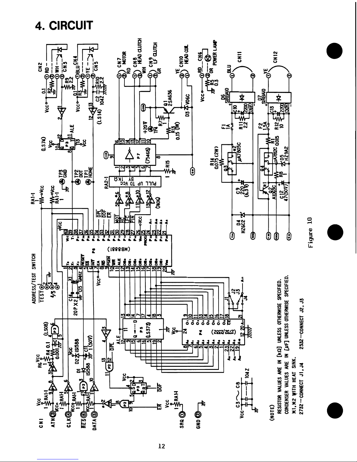
Level
®:
Repairing
PCB
unit
or
replacing defective parts. When fixing
PCB
unit,
refer
to
the
circuit diagram (Figure10 ), the
PCB
view (Figure
11)
and the timing diagrams
(Figure 12
-14).
Level
®:
Replacing defective parts
Q9view
*1
Lead
wire setting note
i/
S-21
Tapping screw M4
x'12
S-21~
_____
W-21
Control
PCB
unit
®
W-21---®
®~W-24
Fuse
(1.5A)
I
4-5*2
,
Fuse
(1
A)
,W-24--®
~:
4-4
I nsert twisted
ends
of
'~I/
:
PCB
receptacle
~:
'
lead
wire and make
sure
o ,
, '
Screw M2 x 0.4 x 6
/I~l
they
are
not shorted.
Spring washer M2
Plain washer M2
*2
4-5 attachment
~
Lamp
PCB
unit
E
+~-4.5
a
;1
Lamp
Wire band A
Wire band B
+-
4-1
*1
S-42
Figure 23
26
Page 29

5. PRINT HEAD UNIT
N-21
W-23
5-1
5-2
5-22
W-23
5-3
5-4
5-5
5-6
5-31
5-7
5-8
Hexagon
nut
(brass) M2 x
0.4
Plain washer M2
(brass)
Head
adjust lever
Head
adjust nut
Screw
(brass)
M2 x 0.4 x 3
Plain washer M2
(brass)
Cable guide
Head
adjust spring
Print
head
unit
Head
spacer
Screw
M3
x 0.5 x 6
Head
board
unit
Head
connector
*2
Be
sure
to
get rid
of
dust, especially iron dust,
from
5-5.
Be
careful not
to
hurt
the flexible
cable. When reassembling, keep pulling the
clutch and revolve
it
counterclockwise
to
move the carrier
unit
to
the center (Refer
to
Figure17)
*3
Barely' tighten 5-2
with
the
print
head
adjust-
ing
tool
(tacking). N-21, W-23 and
5-1
should
be
set
after adjusting the
print
head.
Rubber
leg
Mark
Earth
plate (L)
,........"..,.,.,.~~----..,..Flexible
cable
*1
Removing the hook
of
5-4 using a
print
head
adjusting tool.
___
N-21
II
:--
W-23
~-5-1
$
___
*3
5-2
V-
S
-
22
W-23
~.--5-5
*2
Use
adhesive agent
Lubricate~~
__
J-5
on
top
27
Page 30

6.
LINEFEED
MECHANISM
Repairing methods
Level
®:
Checking, adjusting
or
replacing parts
Level
®:
Replacing machine assembly except checking, cleaning, lubricating
or
adjust-
ing / replacing
6-1
to
6-3.
6-1
E-40
W-51
6-2
6-3
5-28
5-31
6-4
E-38
6-5
6-6
6-7
6-8
5-32
6-9
E-37
6-10.
6-11
W-61
LF rope spring
E-4o.
ring
Plain washer small M5
Reverse
stop claw
Reverse
stop spring
Screw
M2.6 x
0..45
x 6
Screw
M3 x 0..5
x 6
LF solenoid
unit
BE-37
ring
LF claw wheel
Gear pin
6-9*1
Claw wheel
unit
Claw wheel spring
Screw
M3 x
0..5
x 8
LF
claw stopper
E-37
ring
LF dial
Dial clutch spring
Plain washer small
M6
* 1 6-6 should be in
the
groove
of
6-5.
but
not
in
that
of
6-7.
6-~
6-?J2
6-8
W-51
"
E-4o.
~
~
Lubricate
J-5
~
Figure
25
28
Lubricate
~
~/l
SF-100
~~1~
on
LF rope
~
~
W-61
6-11
J 1
\1\
@~66-1o.
!
~
E-37
I
~fr
Page 31

* 1 6-4
and
6-9
adjusting method
i) While pushing down part
®
of
6-4,
fix
6-4
with
S-31
at the position where 6-2 falls
from a
tooth
top
of
6-5. The
screw
S-28
should
be
set
to
the direction
as
shown in
the
left
figure.
ii)
While pressing part ®
of
6-4,
fix
6-9
with
S-32 at the position where ® part
of
6-9
and
(i) part
of
6-7
are
coupled
to
stop the
revolution
of
6-7.
iii)
Confirm linefeed functions
by
pressing part
®.
7. FEED DRUM AND CARRIER UNIT
Repairing methods
Level
®:
Checking, adjusting
or
replacing parts
Level
®:
Replacing machine assembly except checking, cleaning, lubricating, adjusting /
replacing 7-2, 7-10, 7-15
and
7-16,
or
adjusting the ribbon feed board.
S-3O
W-32
7-1
7-2
S-29
7-3
7-4
7-5
7-6
7-7
7-8
E-25
7-9
7-10
7-11
N-31
W-31
W-32
7-12
7-13
7-14
7-15
E-24
7-16
Screw M3 x 0.5 x 4
Plain washer small M3
FPC
guide
Recovery spring
Screw M2.6 x 0.45 x 8
Rope spring
Rope stopper
(1
set)
Head
rope (L) unit
Feed
drum
unit
Drum spring
step
Drum spring
BE-24 ring
Pulley pin
Spring pulley
Rope pulley
Hexagon nut M3 x 0.5
Spring washer M3
Plain washer small M3
Guide pillar
Damper
Carrier
unit
Ribbon
cam
spring
E-24 ring
Ribbon
cam
29
Lubrication on 7-10,
7-11
and
the shaft
of
7-6
Lubricate SF-1oo
on the shaft
of
7-6
feed
drum
unit
Lubricate
SF-1
00 on the groove
and
the shaft
of
7-11
rope pulley (4
pes.)
Lubricate SF-1oo on the groove
and
the shaft
of
7-10 spring pulley
(2
pes.)
Page 32

~
W-32
S-30
I
Lubricate J-5
Figure
26
7-1
'i
E-24
Earth plate (R)
Clutch
(5-29*6
Lubricate
SF-lOa
to
teeth
Lubricate
SF -100
on
head
rope (R)
/
7-6
*4
Page 33

*1
The
cam
7-16
and
the
bend
of
the ribbon
feed
board must
be
parallel.
If
not parallel, ribbon feeding
may function abnormally. In this
case,
you
can
either
change
7-16 or adjust the
bend
of
the ribbon
feed
board
by
using
pliers
to
fit
the
cam
7-16.
Bend
of
ribbon
~
feed
board
,
Cam
7-16
IfthereiSanyg~
here
replace 7-16 I
*2
When
7-14
is
at the home position, there should
be
gaps
between the home
sensor
(Refer
to
Figure
19.).
*3
Firmly insert 7-12 into the earth plate (R)
and
(L),
and
tighten
with
N-31.
*4
Once
you
have
removed
the
feed
drum unit
7-6,
you must install a
new
one.
A new
one,
which
has
six
winds
of
the
head
rope
(R),
is
fixed by a fixing tool. the fixing tool should
be
taken
off
after
you
have
finished
assembling
with
S-29
screws.
Head
rope
(R~
FiXingt~
Be
careful not
to
let the fixing tool
press
the adhered part
of
the
head
rope (R)
7-6
~~@)
F··
::.---:;
Adhered part
of
IXI~ol
head
rope (R)
Figure
27
*5
Insert the rope stopper 7-4 into the rope spring
7-3.
*6
To
fix
the
head
rope (L)
and
(R)
using
screw
S-29:
j)
Inject
screw
lOck
into the
screw
hole
of
the carrier unit.
ii) Tighten the
screw
S-29
to
the extent that the rings
of
the
head
rope
(R)
and
(L)
can
be
re-
volved.
[screw
5-29
: Do not inject here
~
nject screw lock inside
Screw
S-29
~
Ring
must
be
able
, to
turn
around.
.
Screw
lock should not
"'"
be
overflowed.
Figure
27
Screwlock
*7
Check the following after attaching the recovery spring 7-2.
After
manually pulling
and
revolving the clutch counterclockwise to move the carrier unit to the
'right
end,
check the
gaps
of
the rope stopper 7-4
and
the
adhered
position
and
status
of
the
feed
drum
unit
7-6.
Adhered.
position Should have'rooms
~
.
/ when carrier unit
is
, • . / at the rightmost
end.
i_Should
have
rooms
• ! at the home position
Feed
~rum
Head
rope (R)
Unit
7-6
Should
have
gaps
Figure 34
After
pressing
the H solenoid
to
release
the clutch (Figure 6), check the smooth motion
of
the
carrier
unit,its
return
to
the home position,
and
also
the adhered position
and
its status
of
the
feed
drum
unit
7-6 at the home position.
31
Page 34

8.
GEAR
TRAIN
Repairing method.
Level
®:
Checking, adjusting
or
replacing parts
Level
®:
Replacing machine assembly except checking, 'Iubricating
or
replacing / adjust-
ing
8-1
and 8-2.
8-1
'5-31
8-2
E-28
8-3
8-4
8-5
8-6
8-7
E-37
8-8
8-9
8-10
E-38
8-11
8-12
8-13
5-26
8-14
5-33
8-15
·1
The way
to
set 8-10
and
8-9.
Ridge'
• Attaching method
of
8-10
Clut.ch moving spring
Screw
M3
x 0.5 x 6
Dot
~nsor
unit
E-28 ring
Clutch step
Clutch
Spring pan
Clutch spring
Clutch
E-37 ring
Reduction
gear
Gear pin
Rot(:ltion detector
BE-37.ring
Reduction
gear
Gear pin
Reduction
gear
Screw M2.6 x 0.45 x 4
H solenoid
Screw
M3
x 0.5 x 5
Motor
Motor
shaft
When a platen ridge
is
at
the
horizontal position, couple 8-10 and 8-13
in
the status
of
a. and
a,
of
8-10 facing the
two
screw holes
of
the earth plate'(R) respectively.
• Attaching method
of
8-9
Fit
the holes
of
8-10 and the
motor
shaft, and then insert 8-9 using pliers.
*2
First, insert
the
M. stop screw
into
the
rubber
leg
(Figure.
17),
and then
fix
8-2
by
5-31. Make
sure there are
gaps
between
the
grooves
of
8-2 and 8-10.
Page 35

"'"
"'"
'-
'-.....
"
Lubricate SF-l00 on the
saw
~
tooth
part and the tooth
part
of
8-4 and 8-7
*2
8-2
Black and white
Figure
29
8-12
'1
S-31
\
E-38
/8-8
Lubricate SF-l00
to
teeth of 8-13,8-11
and 8-8
Page 36

9.
TRACTOR
Repairing methods
Level
® : Checking, adjusting
or
replacing parts. Replacing machine assembly
if
earth plate
block
is
defective.
Level
® : Replacing machine assembly except checking, lubricating
or
checking/adjusting/
replacing parts
of
9-1
to.
9-4, 9-9
and
9-10.
9-1
S-32
N-31
W-31
W-32
9-2
9-3
9-4
E-75
9-5
9-6
9-7
9-8
E-60
S-32
9-9
9-10
Screw M3 x 0.5 x 8
Soundproof
Hexagon nut
M3
x 0.5
Spring washer M3
Plain washer small M3
Guide pillar
Paper
holder (L)
unit
Paper
holder (R)
unit
BE-74 ring
Platen bearing (Bearing
for
teactor)
Tractor shaft
Pin
feed
roller
Tractor rubber ring
CE-6 ring
Screw M3 x 0.5 x
8
Home
sensor
unit
Rubber
leg
*1
Push
9-9 outside
as
far
as
it
will
go and
fix
with
S-32.
*2
Assemble the
two
9-7
so
that
the
pins
of
them are facing
each
other.
*3 Check
that
the surface
of
9-6 ©
part
is
smooth
and
has
no
scar.
9-5 9-3
~u~ricateSF-l00
~~E-75
*~/""
,ns,de
"--
~
9-7
1fA.
Screw
loc k
.~
E.aO
~9-2
N-31~
<''-
3
n
'~9-6*3
~
.
~-4
W~3t~
/ I ©
~~
W-32
• .
9-1
~/
9-10
./
Lubricate
SF-1OO
inside
Earth plate block
9-10
Page 37

VU.
TROUBLESHOOTING
1. The power lamp does not light
START
Proper intitialization
NO
after power on?
YES
Proper contact between
NO Clean contact
or
connector and lamp
lead
reset
at
correct
wire? (Correct position)
position.
YES
YES
Replace power
lamp.
Repair
PCB
unit
35
YES
Insert
power plug.
NO
YES
Replace
it
( F-3)
NO
Contact between
connector and
5 V
lead
wire
defective?
NO
Output
of
5V
defect
ive?
:
NO
..
I
connector
Replace
~--fuse
YES Replace it.
(
~ange
7.5
-13
VAC)
IS
normal.
Replace
PCB
unit
Page 38

2.
No
initialization
START
H solenoid
moves?
YES
Carrier
unit
returns
to
home position?
YES
Clutch moving
spring OK?
YES
NO
Lubricate
and adjust
position
of
it.
NO
Gaps
between
home
sensor
u.
and carrier u.
abnormal?
NO
Contact between
connector and
LED
or
PH
wire
of
home
sense
defective?
(wrong position)
NO
Zero volts
at LED line?
Repain
PCB
unit
36
YES
Replace feed drum
unit,
head
rope (L)
unit
and rope stopper,
and lubricate.
Replace
or
reset
it.
NO
Lubricate
guide pillar.
YES
Replace it.
YES
Adjust them.
YES
Clean them
or
reset
to
correct position.
YES
>--
Repair
PCB
unit
YES
Replace
it.
Page 39

NO
Wrong position
or
bad contact between
connector and
lead
wire
of
l8V?
NO
Voltage abnormal
on
l8V
line?
,
,
YES
YES
YES
NO
(
'Range
20 --38VAC
)
is
normal
Voltage
reaches
H solenoid?
YES
H solenoid
motion
defective?
NO
H solenoid
broken7
NO
Repair
PCB
unit.
NO
(
~7
-- 20VDC )
IS
normal
YES
YES
37
Replace
it
..
(1.5A, F-2)
Clean them
or
reset
to
correct position.
Replace transformer.
Repair
PCB
unit
Adjust position
of
H solenoid.
Replace H solenoid.
Page 40

3.
The
carrier
unit
does
not
move
with a print
command.
START
YES
NO
Correct position and
Clean them or
good contact between
connector and motor
reset it
at
lead wire?
correct position.
YES
Get rid
of
it
and/or
replace rotation
Foreign object
in
detector, reduction
gear train?
gear, clutch, feed
drum unit
or
rope
NO
stopper.
18
NO
Motor lead
wire
set
at
wront position?
NO
Gear train
abnormal?
NO
Replace feed
YES
drum unit, head rope
(L)
unit and rope
stopper and
lubricate.
Reset it
YES
Reset
or
replace gear
train.
YES Reset
or
replace it.
Motion
of
H
solenoid defective?
YES
Adjust
position
of it.
Voltage reaches
motor?
,
,
YES
NO
YES
(
~7-20VAC)
IS
normal
Replace motor
Replace it.
Repair
PCB
unit
Page 41

4.
The
carrier
unit
overruns
START
Wrong position
or
bad contact between
Clean
or
connector and
LED
or
reset them.
PH
wire
of
dot
sense?
NO
Voltage
on
LED
wire
of home sense zero?
NO
Dot sensor unit
setting abnormal?
No
output
of
dot
sense?
Wrong position
or
bad contact between
connector
and
LED
or
PH
wire
of
home
sense.
NO
Voltage
on
LED
wire
of
dqt
sense zero?
No
output
of home sense?
YES
Repair
CB
unit
YES
Repair
PCB
unit.
YES
Adjust it.
NO
>-----
Replace
dot
sensor unit.
YES
)---
Clean
or
reset them.
YES
>---Repair
PCB
unit.
NO
Replace
)--------
home sensor
unit.
5.
Improper
paper
feed
movement
39
START
YES
Reset
or
clean
passage
of
it.
YES
Replace claw
Manually feeding
paper
by
depressing
LF
solenoid
too
heavy?
NO
LF
rope spring
abnormal?
Function of reverse
stop claw defective?
NO
Wrong position
or
bad contact between
connector and lead
wire of
LF
solenoid?
wheel unit.
Replace
YES tractor shaft
or
lubricate
its bearing.
YES
Reset
or
replace it
YES
Adjust it.
>----Adjust
it.
YES
YES
Replace it
or
reverse
stop
spring
Clean
or
reset it.
Replace it.
Page 42

6.
No printing or poor print quality
START
Proper position
of print head
unit?
NO
l----
Set paper.
\----
Reset it.
Adjust ribbon feed
)--
__
board or replace
ribbon cam or
carrier unit.
>----
Replace it.
7. The upper or lower dots of
printed characters
are
missing.
START
Proper position
of
dot
sensor
unit?
YES
NO
Ad' . .
f'
JUst
position 0
it.
Flexible cable
properly inserted
into head connector?
YES
Correct position
and proper contact
between pin connector
and head board lead
wire?
YES
>-----Replace
print
head unit.
NO
Proper voltage Repair
on pin connector?
PCB
unit.
"
\--
__
~--.J-
...
,
,(17
- 20
VDC
)
YES
isOK
Proper voltage
NO
Replace print
on head connector? head unit.
"
'----~~Y:-=E':"S---'
........ , ...
( 17 - 20
VDC
)
isOK
YES Replace print
head unit.
Repair
PCB unit.
Proper position
between ridges of
platen and
rotation detector?
After removing gear pin from rotation
NO
detector and adjusting coupling
position
of
reduction gear, adjust
position of
dot
sensor unit.
YES
Replace print
head unit.
Page 43

8. The upper and lower dots of printed characters
are
too light.
START
Proper position
NO
of
print
head
unit?
NO
YES
Replace it.
9. Printings
are
too light.
Refer
to
"6.
No printing
or
poor
print
quality."
10. Smudging by ribbon.
START
Proper position
of
print
head
unit?
YES
Any
foreign object
on platen
or
print
head
unit?
YES
Remove
it
and
clean.
NO
NO
NO
41
Adjust
it.
Reset
it.
Replace
print
head
unit.
Reset
it.
If
ribbon
is
twisted,
correct
it.
Adjust
it.
Repiace
print
head
unit.
Page 44

Page 45

Page 46

 Loading...