

Page 1

Commend SIP Series
VERSION 2.0/0612
PRODUCT MANUAL
ENGLISH
Page 2

Commend SIP Series
2 2.0/0612
Manufacturer’s Reference:
This equipment fulfils the requirements of the EU standard 89/336/EEC
(EN 55022, EN 55024).
Therefore this equipment is CE-labelled.
Please keep this description in safe custody!
Attention:
Mounting and installation of the SIP devices and of the equipment may be carried out by authorised service personnel only.
Modules may be exchanged only with voltage switched off.
Before exchanging the modules, ESD precautions have to be observed.
Commend SIP Series
Version: 2.0/0612
Number of pages: 69
Errors and omissions excepted.
Page 3

Commend SIP Series
Vers. 2.0/0612 3
Content
Introduction 4
Commend Security for the World of SIP 4
Technical Data 6
Extent of Supply 9
System Requirements / Compatibility 10
SIP Series Versions 10
Mounting 14
SIP Series P, SIP Series F 14
SIP Series V, SIP Series VE 19
SIP Series M 28
Connection 29
SIP Series P, SIP Series V, SIP Series VE, SIP Series F 29
SIP Series M 31
Configuration via Web Interface 34
1st Connection 34
Configuration of the SIP Station 35
SNMP 58
Appendix 62
Basic Knowledge about Audio Configuration 62
Serverless Operation 64
Display Menu WS 800V / WS 800F 66
Call Initiation at SIP-WS 500F 67
Technical Support 69
Page 4
Introduction Commend SIP Series
4 2.0/0612
Introduction
Commend Security for the World of SIP
SIP Stations with Intercom Power
The full duplex capable stations of the SIP Series links the world of SIP technology with the reliability
and quality of solutions by Commend,
The stations are connected directly to the Ethernet (LAN/WAN) and in this manner are connected to a
compatible SIP Server via the IP-network. The built-in switch with downlink function allows direct connection of an additional IP-device (e.g. an IP-camera).
Besides high volume, the SIP stations provide a numerous amount of further features: Pre-recorded
audio can be applied in a multipurpose manner, e.g. as acoustic indication at line fault or as waiting
information at call initiation, a configurable background noise canceller provides a crystal clear
communication in challenging situations. Furthermore, the stations are perfectly suited for use as door
stations at entry- and gateways, due to integrated relay outputs.
The robust construction of the SIP Series provides full protection against water, dirt and dust – protection class IP 65. Each button can be allocated to a call number and the relevant label area can be filled
in individually.
Speech Connection according SIP Standard
The speech connection is established via Voice over IP (VoIP) according the SIP standard over the connected Ethernet LAN, whether with assistance of a SIP capable PBX, of a SIP provider or via dialling an
IP address directly.
Note:
The several versions of the SIP Series are described on page 10.
WHAT IS SIP?
The network protocol SIP is only one among many protocols which are used for VoIP; the “Session Initiation Protocol” establishes the conversation.
This means, SIP is only signalling the conversation. After that, the Session Description Protocol (SDP) negotiates the conversation modalities: audio codec and transmission protocol. The latter is responsible for
the actual data exchange.
The actual data stream, i.e. the coded speech, is transmitted via the Realtime Transport Protocol (RTP).
This protocol dismantles the audio data into packets and is sending them over UDP – i.e. the User Datagram Protocol (UDP) is responsible for the transmission of the data packets.
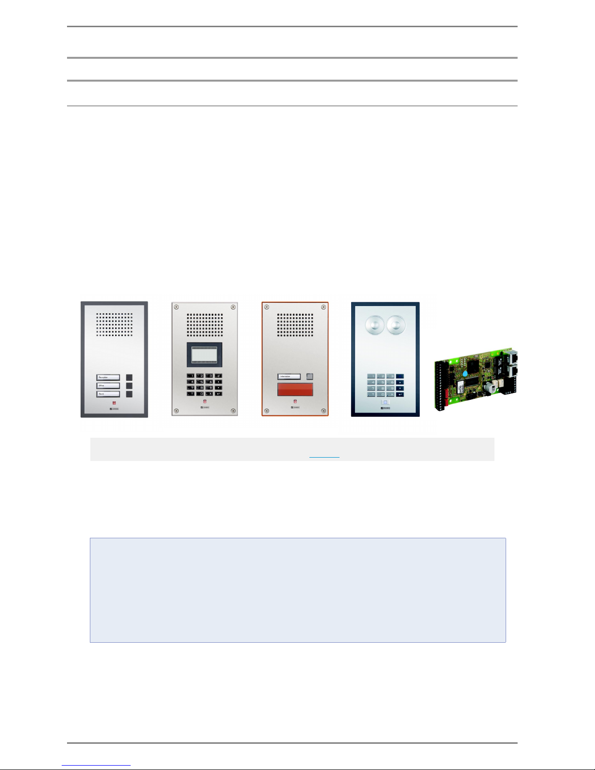
SIP Series P SIP Series V SIP Series VE SIP Series F SIP Series M
Page 5

Commend SIP Series Introduction
2.0/0612 5
Overview of Features
Very high volume
Full Duplex for natural, hands-free communication
Display support NEW!
Full keypad support NEW!
Handset support NEW!
Local directory support NEW!
Chain call support (e.g. automatic processing of call sequences) NEW!
STUN support NEW!
SNMP for surveillance of the station
Using Pre-recorded audio as:
Waiting information at call initiation
Individual call tone for call initiation
Location message
Acoustic indication at line fault
Control of the 2 relays e.g. as door opener via
DTMF post-dial or
Web – or as:
Attendant contacts for various functions, e.g.:
Additional signalisation while ringing, during a call or in case of malfunction
Three inputs for connecting add-on call button modules NEW!
Remote controllable via HTTP; Line-Out (SIP stations)/Line-In (SIP moduls) NEW!
Server redundancy NEW!
Operation without Server possible
Configurable Acoustic Echo Canceller (AEC)
Configurable Background Noise Canceller
Adaptive jitter buffer
Complies with SIP standard for easy integration in every SIP capable PBXes
Integrated webserver for configuration & firmware update
Adjustment of microphone sensitivity and volume
Flexible operation via Power over Ethernet or via external power supply
3.4 kHz speech quality for optimum intelligibility and compatibility
Increased system availability by redundant LAN infrastructure
The integrated data switch function enables the connection of further IP devices, e.g. IP camera
Configurable Auto Answer Function
Instant boot (system boot within seconds)
Communication via IP-data networks – no additional cabling required
Robust construction with protection class IP 65 – vandal resistant versions additionally mechanical
impact resistance up to IK 09
Series F: Dirt-repellent foil surface, resistant to cleaning agents and disinfectants
Configurable backlight
VOIP ACCORDING SIP STANDARD – HOW DOES IT WORK?
Each VoIP subscriber is registered automatically with the respective IP address at a server of the corresponding SIP provider. This provider assigns a new address to the subscriber according to the rules of the
SIP standards, in form of “sip:[email protected]”. This address is allocated to a normal telephone number.
If a subscriber enters this telephone number in order to establish a conversation, it will be translated into
the SIP address at first. In this manner, it is possible to identify the current IP address of the called subscriber. The server is sending this information back to the calling subscriber, whose hardware and software
now is forwarding the audio packets to the IP address of the conversation partner. In order that this conversation partner is able to answer, the calling subscriber also forwards his own, current IP address.
Page 6
Introduction Commend SIP Series
6 2.0/0612
Technical Data
Network, Codecs
Power Supply
Hardware
Note:
In the following tables the technical data of all „
SIP Series Versions” are listed.
DTMF Decoding: RFC 2833
SIP User Agent (UDP): RFC 3261
IP Protocol: IPv6 ready
IPv4, TCP, UDP, HTTP, RTP, RTCP, DHCP, SNMPv2c, STUN
Ports: Web interface for configuration (http): TCP Port 80
SIP: UDP Port 5060
RTP: UDP Port 7078 (incoming)
Optional DNS: UPD and TCP Port 53
Optional SNMP: UDP Ports 160 and 161
Ethernet: 2 x 10/100 MBit/s (Full/Half Duplex)
Codecs: G.711 a-Law
G.711 µ-Law
prepared for G.722
Frequency range 300 – 3,400 Hz
Power consumption: 1,6 W idle
approx. 2 W at conversation (depending on volume)
PoE (Power over Ethernet): Standard IEEE 802.3af
Power consumption of the terminal device:
Class 0 (0.44 W to 12.95 W)
SIP Series P, SIP Series V, SIP Series VE only:
Power supply: 24 VDC ± 2 V, 500 mA or PoE
Attention:
It is mandatory to ensure a correct power supply of the SIP station: min. 22 VDC, max. 26 VDC
SIP Series M only:
Power supply: 12 – 24 VAC or 15 – 35 VDC, 500 mA or PoE
RAM Memory: 32 MByte
Flash Memory: 8 MByte
Handset, Headset: EM sensitivity: 14 mV
eff
EM impedance: 3.3 kΩ / EM supply: 2.5 V
EP level: 850 mV
eff
at 0 dBm0 / EP impedance: 200 Ω
Amplifier: Built-in amplifier class “D” with 2.5 W
Outputs: 2 SPDT relay outputs
30 V / 1 A: 100,000 make-and-break cycles
Inputs: 3 inputs for floaing contacts
Relative Humidity: up to 95% not condensing
Connection: pluggable screw terminals
IP Uplink/Downlink:
shielded RJ 45 modular jacks
Cabling: min. Cat. 5
Page 7

Commend SIP Series Introduction
2.0/0612 7
Housing, Mounting
SIP Series P, SIP Series V, SIP Series VE, SIP Series F only:
Operating temperature range: –20° C to +60° C (–4° F to 140° F)
Storage temperature range: –20° C to +60° C (–4° F to 140° F)
Microphone: Omnidirectional electret microphone for
max. 7 m (23 ft) speaking distance
Loudspeaker: Special membrane type for optimal sound quality,
sound pressure: 85 dB/1 W/1 m (3.28 ft), 2 x 8 Ω
Line output: for connection of loudspeaker module
Status indication: red LED
Keypad, call button: SIP Series F, SIP-WS 800x: alphanumeric full keypad, white
backlight activation force: 3 N, 1 x 10⁶ cycles,
SIP WS 20xP, SIP-WS 20xV, SIP Series VE: 1 – 3 direct dialling
buttons
SIP-Serie VE only: large red emergency call button
Display: SIP-WS 800x: Mono-LCD display,
128 x 64 pixel, white backlight
SIP Series M only:
Operating temperature range:: –40° C to +70° C (–40° F to 158° F)
Storage temperature range:: –40° C to +70° C (–40° F to 158° F)
Microphone input: for electret microphone or
dynamic microphone
Mic Input: nominal level 2.8 mV on 3.3 kΩ
(Mic-feeding voltage 2.5 V)
Connection for loudspeaker: 2.5 W at 4 Ω / 1.5 W at 8 Ω
LS-Output: max. 3.5 V
eff
(LS-Pot max)
for feed-in of audio
(e.g. music, radio conference)
Line-Input: nominal level 0 dBu 0.775 V at 10 kΩ
Status indication: Possibility for connection of a LED 6 mA
Call button: Possibility for connection of 3 single buttons
SIP Series P, SIP Series F:
IP rating: IP 65
Front panel: SIP Series P: Polycarbonate
SIP Series F: Polycarbonate with protective foil
Additional mounting material: Flush mount kit WSFB 50P
Surface mount kit WSSH 50P
Measurements: Mounting with flush mount kit, surface mount kit:
see page 14 to page 18
Weight incl. package: approx. 750 g (1.65 lbs)
Colour: front panel: light-grey (like RAL 7035)
front panel frame: graphite-grey (like RAL 7024)
Page 8

Introduction Commend SIP Series
8 2.0/0612
SIP Series V, SIP Series VE:
IP rating: IP 65
Mechanical impact resistance acc. EN 62262 SIP Series V: IK 09
SIP Series VE: IK 08
SIP-WS 800V: IK 07
Front panel: Stainless steel, 3 mm (0.12 in)
Additional mounting material: Flush mount kit WSFB 50V
Flush mount kit WSFB 50V FL
Surface mount kit WSSH 50V
Rain protection roof WSRR 50V
Measurements: Mounting with flush mount kit, surface mount kit:
see see page 19
to page 27
Weight incl. package: approx. 1500 g (3.3 lbs)
SIP Series M:
Measurements: SIP-ET 908A: 65 x 130 x 18 mm (2.56 x 5.12 x 0.71 in)
SIP-ET 908A-1: 65 x 130 x 21 mm (2.56 x 5.12 x 0.83 in)
Weight incl. package: ca. 220 g (0.5 lbs)
Page 9

Commend SIP Series Introduction
2.0/0612 9
Extent of Supply
SIP Series
Additional Mounting Material
The following listed mounting material must be ordered separately:
”SIP Series P”
”SIP Series F”:
SIP station
SIP-WS 800F MD:
Locking block with
screw
Short reference
”SIP Series V”:
SIP station
Screws for mounting
Short reference
”SIP Series VE”:
SIP station
Screws for mounting
3 x paste-on label (“SOS”/
“EMERGENCY”/“HELP”)
for emergency call button
Short reference
”SIP Series M”:
SIP module
4 fixing spacers with M3
thread
Short reference
WSFB 50P:
Flush mount box plastic
(incl. cavity wall claws & cover lid)
Mounting frame plastic
(incl. gaskets and mounting screws)
Cable fixing brackets (incl. screws)
Short reference
Weight incl. package: approx. 380 g (0.84 lbs)
WSSH 50P:
Surface mount box (incl. gaskets)
4 x IP 65 cable feed through
Wall mount kit
(screws, dowels, gasket rings and washers)
Cable fixing brackets (incl. screws)
Short reference
Weight incl. package: approx. 300 g (0.66 lbs)
WSFB 50V:
Flush mount box plastic
(incl. cavity wall claws & cover lid)
Mounting frame plastic
(incl. mounting screws)
Flush mount frame metal & gasket
Cable fixing brackets (incl. screws)
Short reference
Weight incl. package: approx. 540 g (1.2 lbs)
WSFB 50V FL:
Flush mount box plastic with mount frame metal
(incl. cover lid)
Cable fixing brackets (incl. screws)
Short reference
Weight incl. package: approx. 540 g (1.2 lbs)
WSSH 50V:
Surface mount box metal
(incl. 6 x dummy plugs)
Plastic box
4 x IP 65 cable feed through
2 x sabotage plates
(currently not applicable for SIP stations)
Wall mount kit
(screws, dowels, gasket rings and washers)
Cable fixing brackets (incl. screws)
Short reference
Weight incl. package: approx. 945 g (2.08 lbs)
WSRR 50V:
Rain Protection Roof
Fixing screws
Short reference
Weight incl. package: approx. 465 g (1.03 lbs)
Note:
For mounting of the several surface mount kits and surface mount kits see page 14
.
Page 10
Introduction Commend SIP Series
10 2.0/0612
System Requirements / Compatibility
Compatible SIP Server (see ”Compatibility SIP PBX”) or
G8-VOIPSERV (for additional features) incl. Asterisk Server
Compatibility SIP PBX
Basically the SIP modules can be used with any SIP server. The following server types have been tested
explicitly by Commend and therefore a proper functionality can be confirmed:
*The listed products and company names are brand names or registered trademarks of their respective owners.
SIP Series Versions
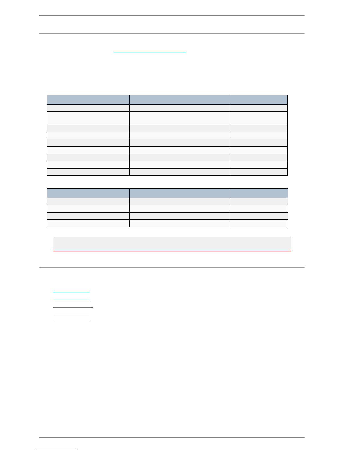
The stations of the SIP Series are available in 5 different versions:
”
SIP Series P”
”SIP Series V”
”SIP Series VE”
”SIP Series F”
”SIP Series M”
Manufacturer* Type Version
Digium Asterisk Version 1.2, 1.4, 1.6
Cisco
Cisco Call Manager
Cisco Unified Communication Manager
Version 5 or higher
Nortel CS1000 Version 6
Innovaphone Virtual Appliance IPVA Version 9 final
Alcatel OmniPCX Enterprise OXE
Siemens Hipath 4000 Version 5
3CX 3CX for Windows 3CX PhoneSystem 9
Starface Starface free Version 4.6.5.1
Aastra MX-ONE Version 4.1 SP 1
VoIP Provider Type Version
Sipgate Sipgate.at, Sipgate.de May 2012
Vodafone Arcor vodafone.de January 2011
blueSIP bluesip.net May 2011
dus.net dus.net May 2012
Attention:
Not compatible: Microsoft Lync
Page 11
Commend SIP Series Introduction
2.0/0612 11
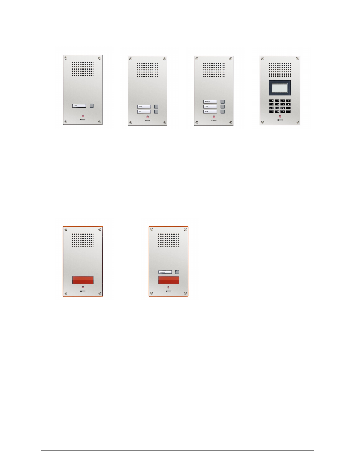
SIP Series P
SIP-WS 20xP
SIP station with up to 3 programmable direct dialling buttons (white backlight) in polycarbonate
construction for interior and outdoor areas.
Each button can be allocated to a call number and the relevant label area can be filled in individually.
The robust construction provides full protection against water, dirt and dust – protection class IP 65.
SIP-WS 800P
SIP station with an alphanumeric keypad and function keys with white backlight, in polycarbonate
construction for interior and outdoor areas.
The station provides a LCD graphic display with white backlight.
The robust construction provides full protection against water, dirt and dust – protection class IP 65.
SIP Series V
SIP-WS 20xV
Vandal resistant SIP stations with up to 3 programmable direct dialling buttons (white backlight),
stainless steel front panels with 3 mm (0.21 in) thickness, poke protection and special screws.
Each button can be allocated to a call number and the relevant label area can be filled in individually.
The robust construction provides full protection against water, dirt and dust – IP rating IP 65 and
mechanical impact resistance IK 09.
SIP-WS 800V
Vandal resistant SIP station with an alphanumeric keypad and function keys with white backlight,
stainless steel front panels with 3 mm (0.21 in) thickness, poke protection and special screws.
The station provides a LCD graphic display with white backlight.
The robust construction provides full protection against water, dirt and dust – IP rating IP 65 and
mechanical impact resistance IK 07.
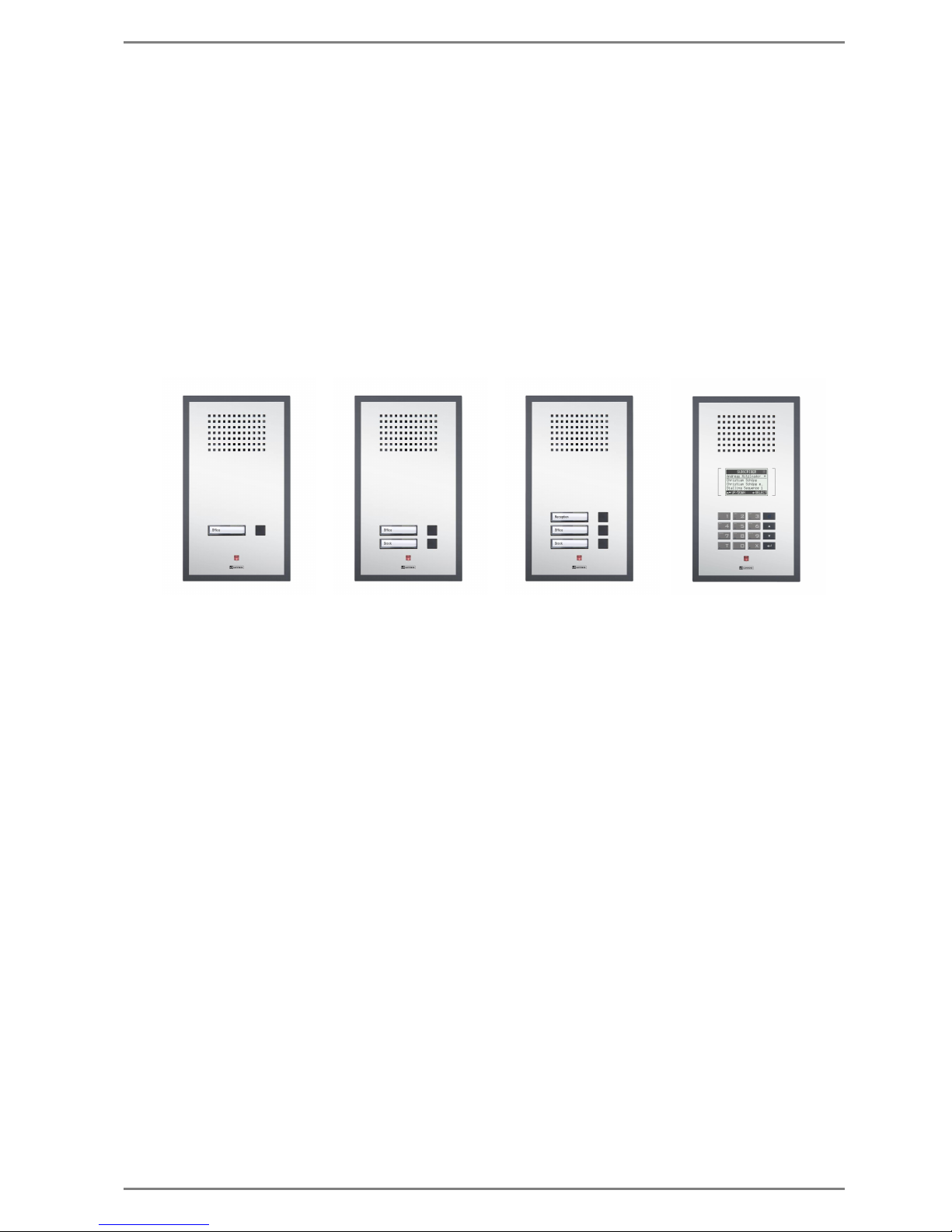
SIP-WS 201P:
(1 direct dialling button)
SIP-WS 202P:
(2 direct dialling buttons)
SIP-WS 203P:
(3 direct dialling buttons)
SIP-WS 800P:
(keypad, display)
Page 12
Introduction Commend SIP Series
12 2.0/0612
SIP Series VE
Vandal resistant SIP emergency stations with up to 2 programmable direct dialling buttons, stainless
steel front panels with 3 mm (0.21 in) thickness, poke protection and special screws.
The red emergency call button is easily visible from a considerable distance and can be activated
quickly in emergency situations. Each button can be allocated to a call number and the label area of
the direct dialling button (white backlight) of the SIP-WS 212V can be filled in individually.
The robust construction provides full protection against water, dirt and dust – IP rating IP 65 and
mechanical impact resistance IK 08.
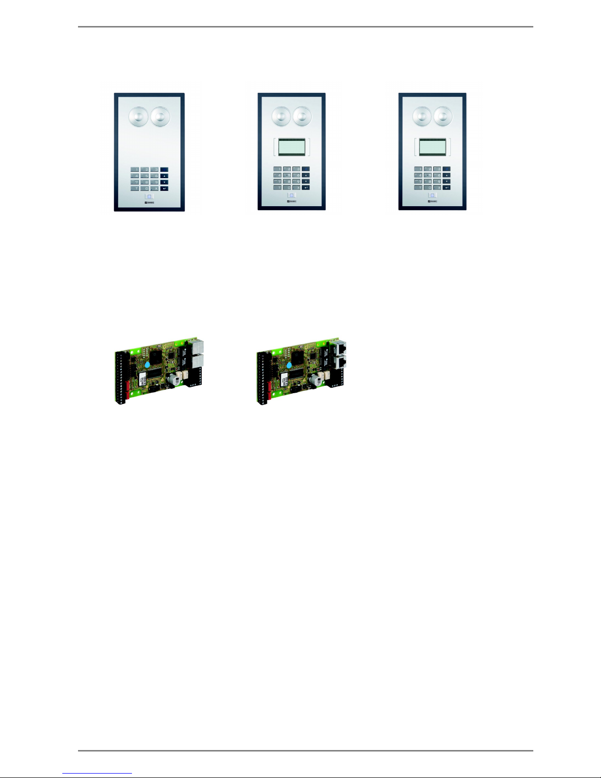
SIP Series F
SIP station with an alphanumeric keypad and function keys with white backlight, in polycarbonate
construction with a dirt-repellent foil surface (resistant to cleaning agents and disinfectants), for interior and outdoor areas.
The station SIP-WS 800F additionally provides a LCD graphic display with white backlight. The sta-
tion SIP-WS 800F MD additionally provides an anti-bacterial foil surface.
The robust construction provides full protection against water, dirt and dust – protection class IP 65.
SIP-WS 201V:
(1 direct dialling button)
SIP-WS 202V:
(2 direct dialling buttons)
SIP-WS 203V:
(3 direct dialling buttons)
SIP-WS 800V:
(keypad, display)
SIP-WS 211V:
(1 direct dialling button)
SIP-WS 212V:
(2 direct dialling buttons)
Page 13
Commend SIP Series Introduction
2.0/0612 13
SIP Series M
SIP modules for integration in existing housings and panels or building of customer specific stations.
Available in 2 different versions: with RJ 45 sockets mounted horizontally or vertically.
Application examples are for e.g. emergency stations at highways, park ticket machines or also for
smaller systems with door functions.
SIP-WS 500F:
(without LCD-Display)
SIP-WS 800F:
(with LCD-Display)
SIP-WS 800F MD:
(with LCD-Display)
SIP-ET 908:
(RJ 45 sockets mounted
SIP-ET 908-1:
(RJ 45 sockets mounted
horizontally)
vertically)
Page 14
Mounting Commend SIP Series
14 2.0/0612
Mounting
SIP Series P, SIP Series F
For installation additional mounting material is required (must be ordered separately).
Following additional mounting material is available for the SIP Series P, SIP Series F:
Flush mount kit WSFB 50P
Surface mount kit WSSH 50P
The mounting instruction is split into following sections:
„
Measurements of the Front Panel” of the stations of SIP Series P and SIP Series F
„
Measurements Flush Mount Kit WSFB 50P”
„Mounting Flush Mount Kit WSFB 50P”
„Measurements Surface Mount Kit WSSH 50P”
„Mounting Surface Mount Kit WSSH 50P”
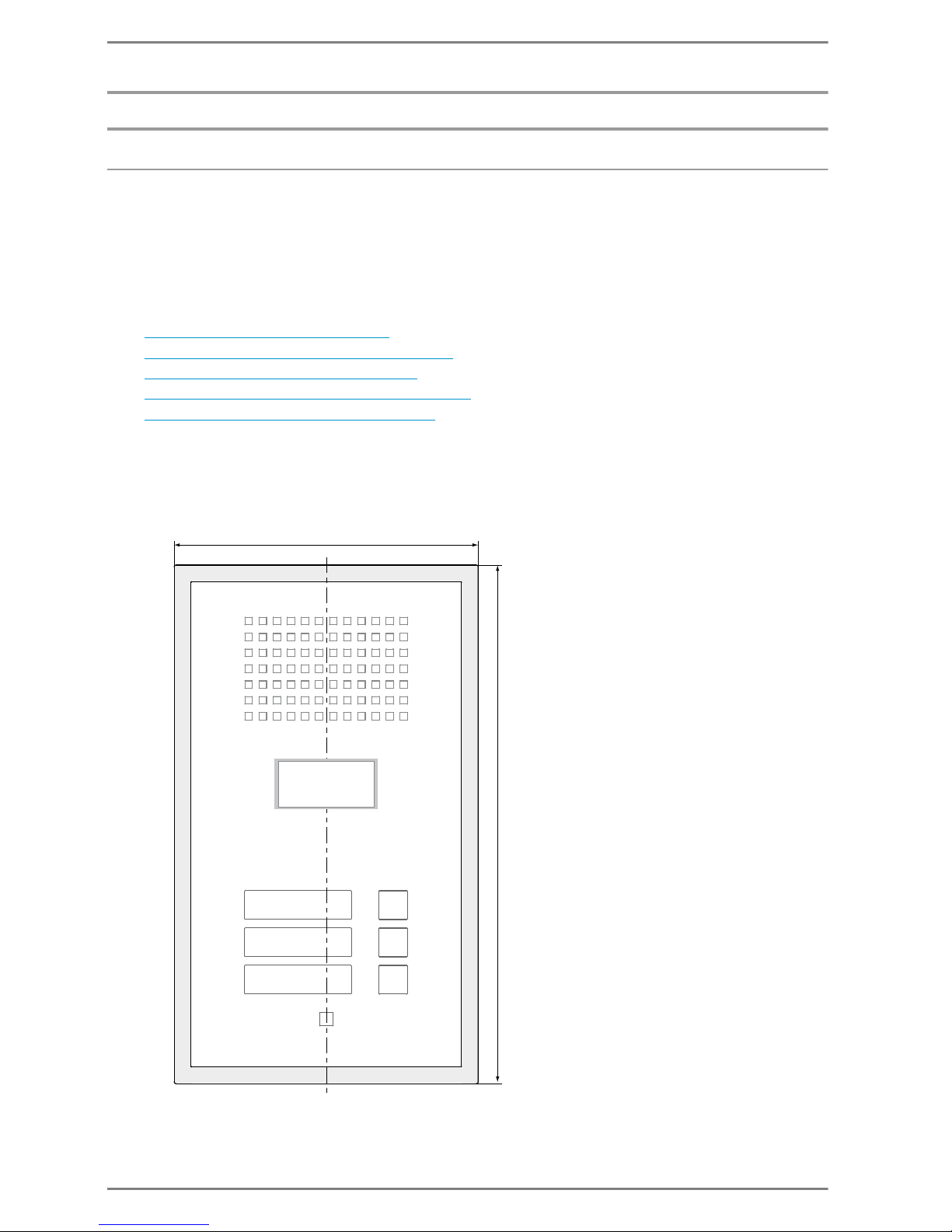
Measurements of the Front Panel
Measurements in mm (inch), not to scale!
165 (6.5)
280 (11)
Depth: 13 (0.51)
cavity wall mounting: 15 (0.59) (Öshadow gap between front panel & wall)
INNER CONTOURS
VARY DEPENDING ON
VERSION
OF STATION
Page 15
Commend SIP Series Mounting
2.0/0612 15
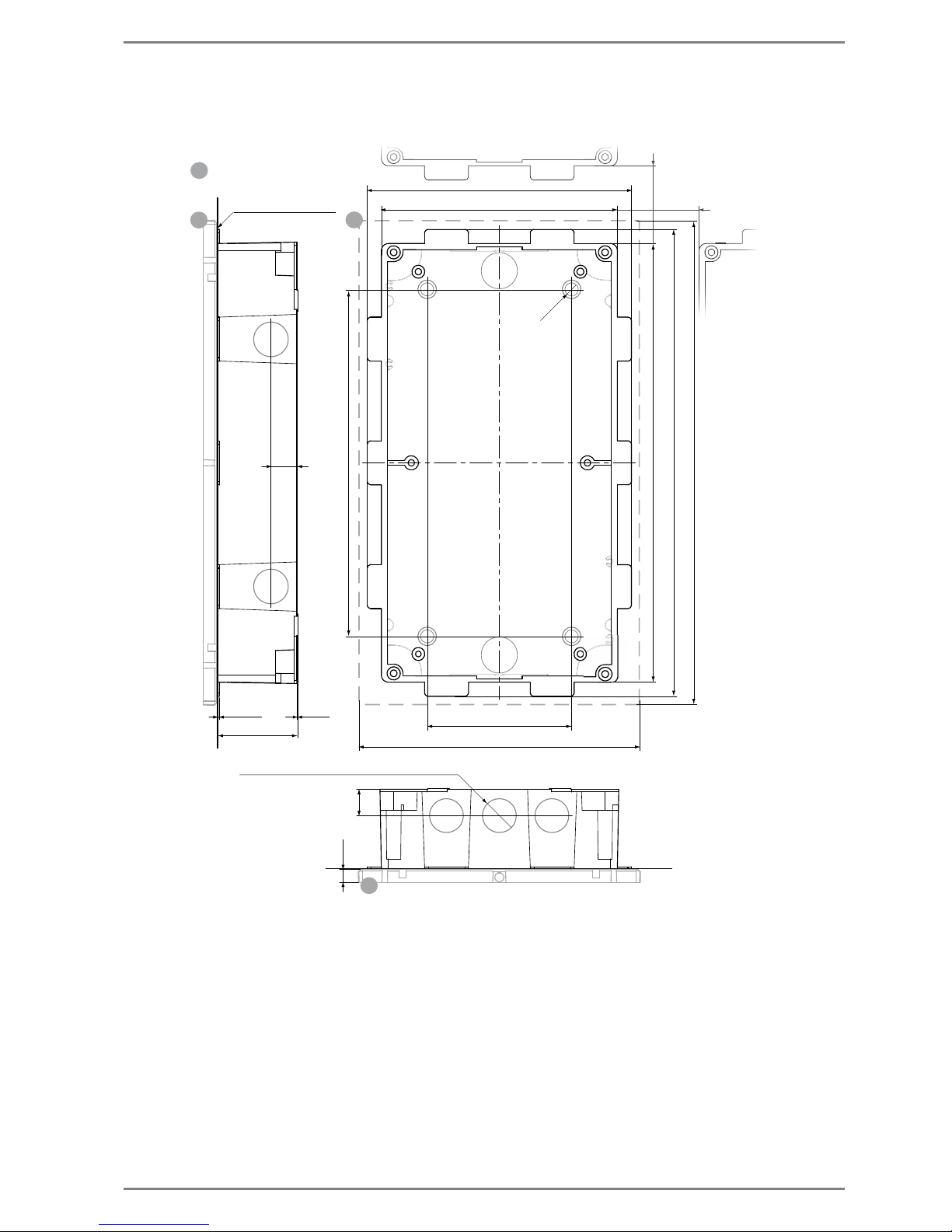
Measurements Flush Mount Kit WSFB 50P
Measurements in mm (inch), not to scale!
MR
MR
MR
MR
12x Expansion openings (can be broken out) Ø 21
150 (5.91)
135.6 (5.34)
82 (3.23)
159.5 (6.28)
1 (0.04) 0.5
(0.02)
45.5
(1.79)
15
(0.59)
(0.59)
265 (10.44)
274.5 (10,82)
8
(0.32)
15
250.6 (9.87)
(0.3)
4x
Ø 7. 5
...... Mounting frame
197 (7.76)
front flush with plaster
30 (1.18)*
30 (1.18)*
*Mounting distance
between flush
mount boxes
Page 16
Mounting Commend SIP Series
16 2.0/0612
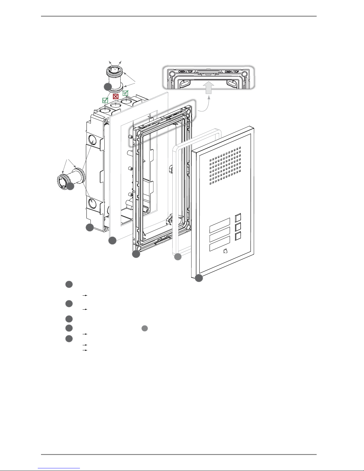
Mounting Flush Mount Kit WSFB 50P
T
R
R
1
4a
4a
2
5
1
1
2
4
3
5
4
3
..... Front panel (plastic) with station electronics
MOUNTING
DIRECTION
..... Top gasket for mounting frame (mounted ex works)
..... Mounting frame (plastic)
..... Gasket
..... Flush mount box (plastic)
..... Connection spacer (with gaskets) for connecting two flush mount boxes and
for cable feed through
To corresponding expansion opening of
flush mount box of e.g. WS expansion module
Mounting: Press the front panel onto the mounting frame.
Dismounting: Pull off the front panel.
Screw mounting frame onto the flush mount box - screws in extent of supply
For cavity wall mounting or installation in a desk, the cavity wall claws have to be used.
(wall thickness: 5 mm to 30 mm / 0.19 in to 1.18 in)
If possible, then 2 connection spacers shall be used per expansion
(at deppened openings, see above)
Illustration
front panel
*
gasket
gasket
Page 17
Commend SIP Series Mounting
2.0/0612 17
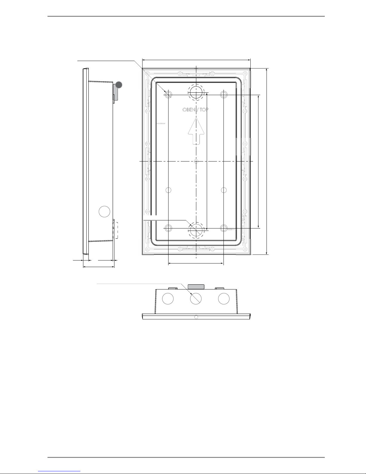
Measurements Surface Mount Kit WSSH 50P
Measurements in mm (inch), not to scale!
1
160 (6.3)
275 (10.84)
46.5 (1.83)
(0.33)
2 (0.08)8.5
197 (7.76)
12x Expansion openings (can be broken out) Ø 21
82 (3.23)
202.5 (7.97)
4x Mounting openings Ø 7.5 (0.3)
(can be broken out)
2 x rear openings
Page 18
Mounting Commend SIP Series
18 2.0/0612
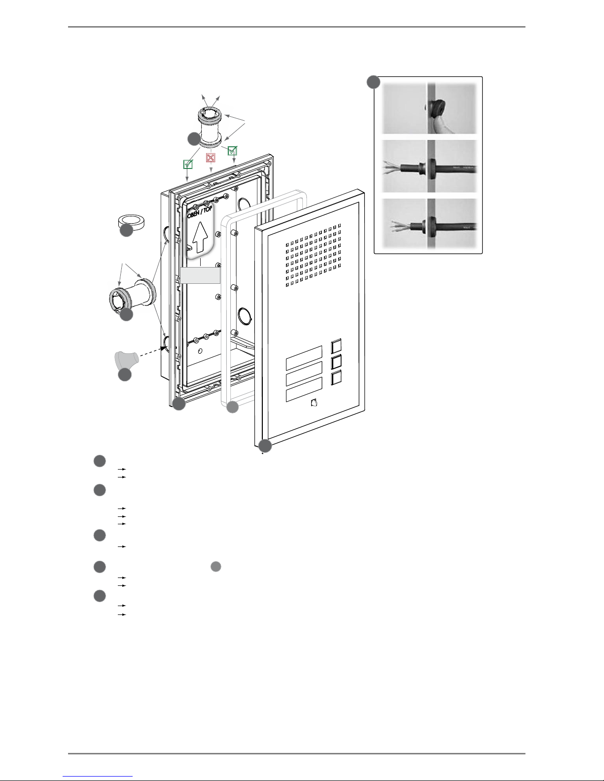
Mounting Surface Mount Kit WSSH 50P
T
R
R
4a
3
2
1
2
5
4
2
1
3
4a
4
5
3
..... Front panel (plastic) with station electronics
..... Surface mount box (plastic)
..... Top gasket for surface mount box (mounted ex works)
MOUNTING
DIRECTION
To corresponding expansion opening of
surface mount box of e.g. WS expansion module
Illustration
front panel
*
gasket
gasket
Snap in
Insert cable
Pull back tight
Dismounting: Pull off the front panel.
Mounting: Press the front panel onto the surface mount box
..... IP 65 cable feed through
..... Connection spacer (with gaskets) for connecting two surface mount
boxes and for cable feed through
The expansion openings have to be broken out with a blunt object at the outer notch!
If possible, 2 connection spacers shall be used per expansion.
Make sure the connection spacer is snaped-in correctly in the expansion opening!
The expansion openings have to be broken out with a blunt object at the outer notch!
If the rear opening is used, attach the gasket at the backside of the flush mount box (see Measurements).
..... Gasket for expansion opening at the rear of the housing
The cable feed through can be put in after breaking out the expansion openings
(installation cable feed through see above).
Mounting via wall mounting kit (screws, dowels, gasket rings and washers) – in extent of supply.
Washer and gasket ring have to be mounted inside the surface mount box.
Page 19
Commend SIP Series Mounting
2.0/0612 19
SIP Series V, SIP Series VE
For installation additional mounting material is required (must be ordered separately).
Following additional mounting material is available for the SIP Series V and SIP Series VE:
Flush mount kit WSFB 50V
Flush mount kit WSFB 50V FL
Surface mount kit WSSH 50V
Rain protection roof WSRR 50V
The mounting instruction is split into following sections:
„
Measurements of the Front Panel” of the stations of SIP Series V and SIP Series VE
„
Measurements Flush Mount Kit WSFB 50V”
„Mounting Flush Mount Kit WSFB 50V”
„Measurements Flush Mount Kit WSFB 50V FL”
„Mounting Flush Mount Kit WSFB 50V FL”
„Measurements Surface Mount Kit WSSH 50V”
„Mounting Surface Mount Kit WSSH 50V”
„Measurements Rain Protection Roof WSRR 50V”
„Mounting Rain Protection Roof WSRR 50V”
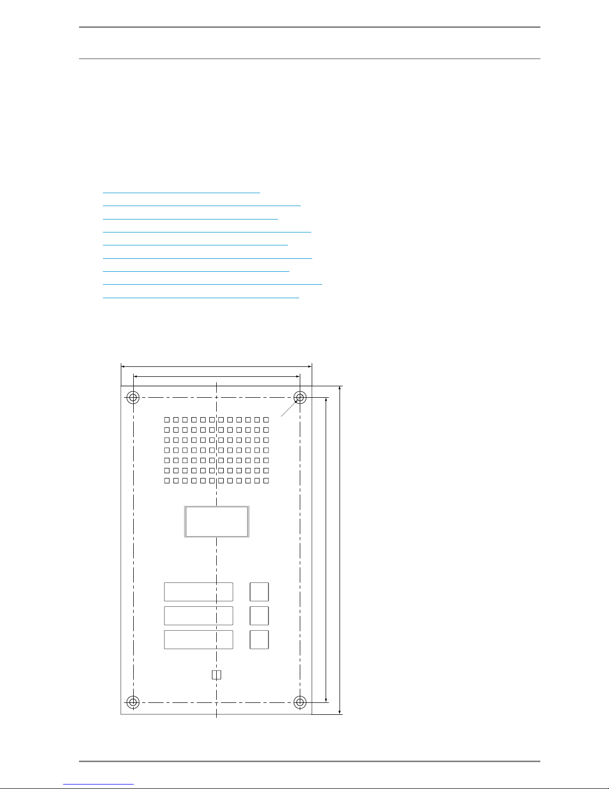
Measurements of the Front Panel
Measurements in mm (inch), not to scale!
160 (6.3)
140 (5.5)
275 (10.84)
255 (10.05)
4x
Ø
7
(0.28)
INNER CONTOURS
VARY DEPENDING ON
VERSION
OF STATION
Page 20
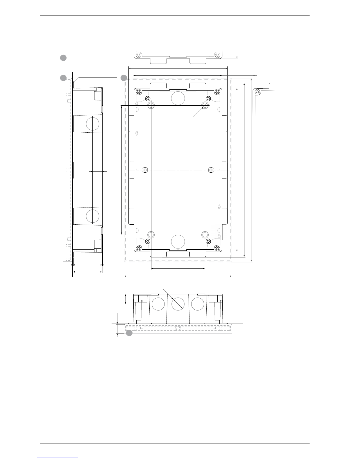
Mounting Commend SIP Series
20 2.0/0612
Measurements Flush Mount Kit WSFB 50V
Measurements in mm (inch), not to scale!
MR
MR
MR
12x Expansion openings (can be broken out) Ø 21
150 (5.91)
135.6 (5.34)
82 (3.23)
1 (0.04) 0.5
(0.02)
45.5
(1.79)
15
(0.59)
(0.59)
265 (10.44)
(0.55)
15
250.6 (9.87)
(0.3)
4x
Ø
7. 5
164 (6.46)
279 (10.99)
14
MR
.... Flush mount frame (metal)
with mounting frame (plastic)
197 (7.76)
front flush with plaster
30 (1.18)*
*Mounting distance
between flush
mount boxes
30 (1.18)*
Page 21
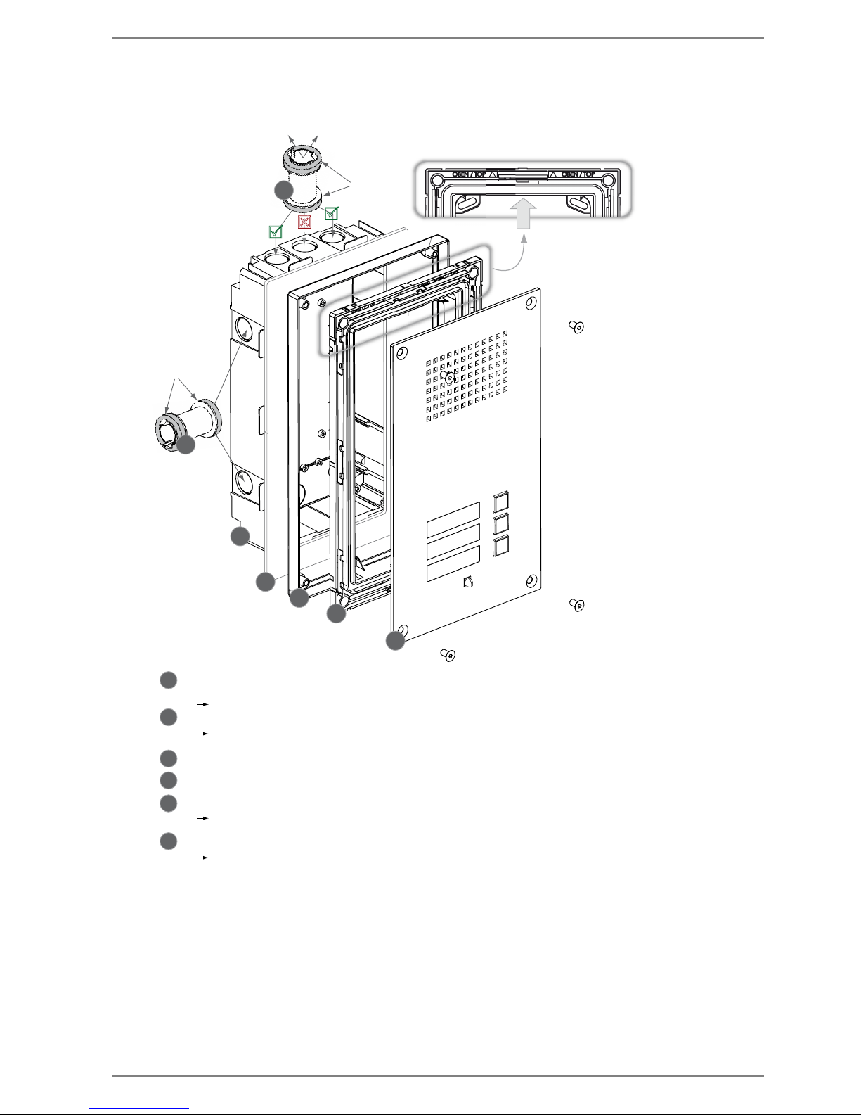
Commend SIP Series Mounting
2.0/0612 21
Mounting Flush Mount Kit WSFB 50V
T
R
R
5
1
3
4
2
1
1
2
3
4
6
6
5
..... Front panel (metal) with station electronics
MOUNTING
DIRECTION
..... Mounting frame (plastic)
..... Flush mount frame (metal)
..... Gasket
..... Flush mount box (plastic)
To corresponding expansion opening of
flush mount box of e.g. WS expansion module
..... Connection spacer (with gaskets) for connecting two flush mount boxes and
for cable feed through
Illustration
front panel
*
Screw front panel onto flush mount frame
Screw mounting frame together with the flush mount frame (metal) and the gasket onto the flush mount box
(screws in extent of supply)
If possible, then 2 connection spacers shall be used per expansion (at deppened openings, see above)
gasket
gasket
For cavity wall mounting or installation in a desk, the cavity wall claws have to be used.
(wall thickness: 5 mm to 30 mm / 0.19 in to 1.18 in)
Page 22
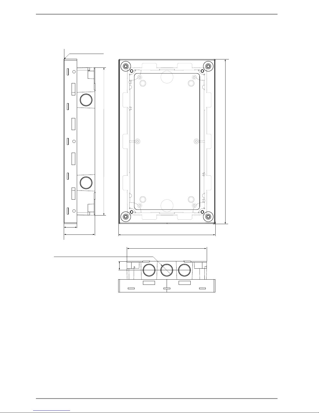
Mounting Commend SIP Series
22 2.0/0612
Measurements Flush Mount Kit WSFB 50V FL
Measurements in mm (inch), not to scale!
(0.59)
15
12x Expansion openings (can be broken out) Ø 21
164 (6.46)
279 (10.99)
251.6 (9.88)
22
(8.87)
53 (2.09)
136 (5.35)
front flush with plaster
Page 23
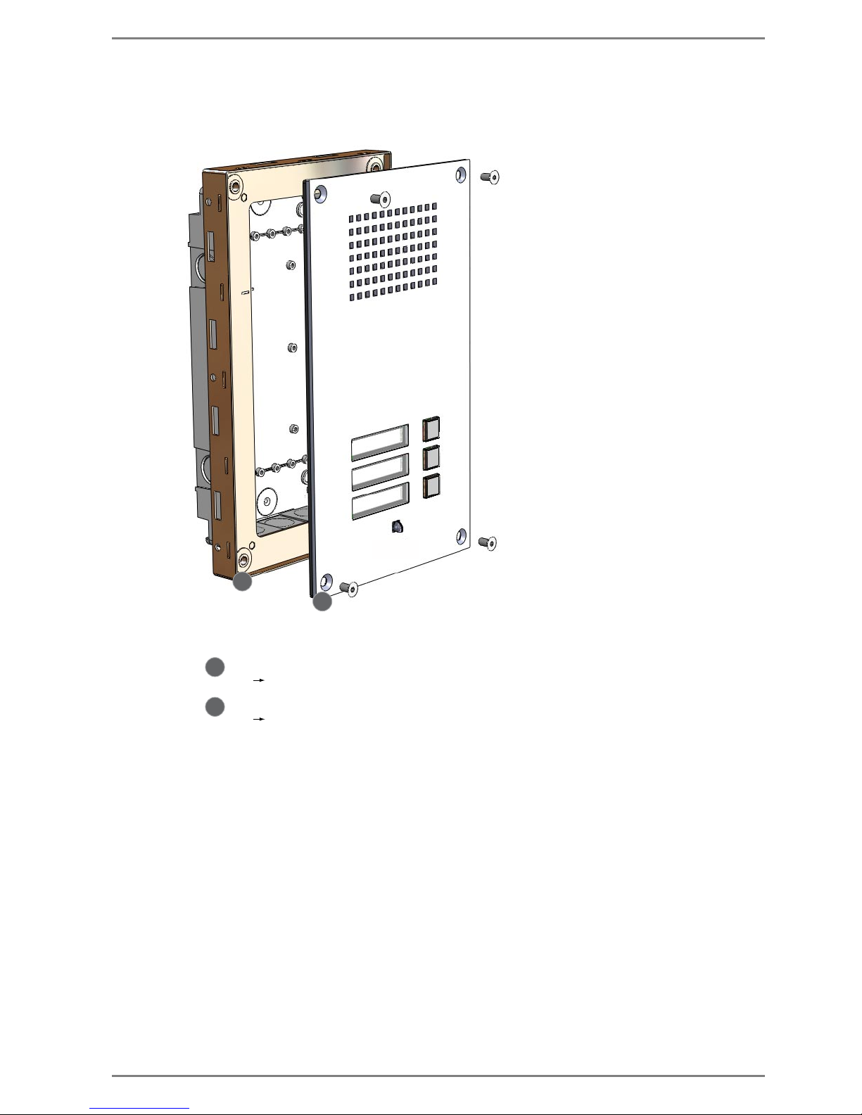
Commend SIP Series Mounting
2.0/0612 23
Mounting Flush Mount Kit WSFB 50V FL
...oben, Montagerichtung beachten...this side up, mounting direction
1
2
1
2
..... Front panel (metal) with electronics and gasket
..... Flush mount box (plastic) with Flush mount frame (metal)
Illustration
front panel
*
Screw front panel onto flush mount frame
Install the flush mount box by moulding into plaster or concrete.
Do not remove plaster cover until the flush mount box is mounted.
Page 24
Mounting Commend SIP Series
24 2.0/0612
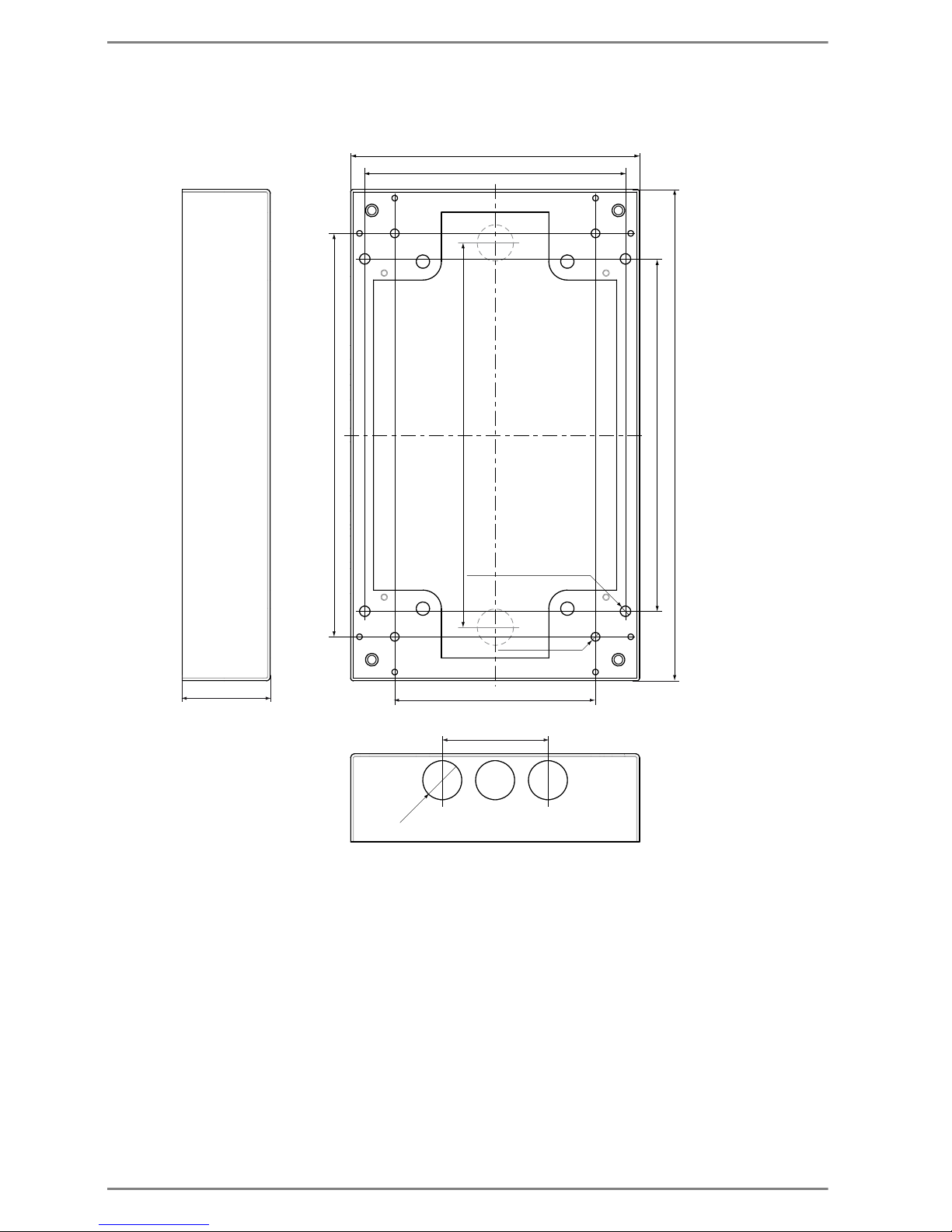
Measurements Surface Mount Kit WSSH 50V
Measurements in mm (inch), not to scale!
279 (10.99)
200 (7.88)
164 (6.46)
(0.87)
148 (5.83)
50 (1.97)
229 (9.02)
114 (4.49)
4x
Ø 5 (0.2)
6x
Ø 22
218 (8.58)
60 (2.36)
4x Mounting openings Ø 6 (0.24)
Page 25
Commend SIP Series Mounting
2.0/0612 25
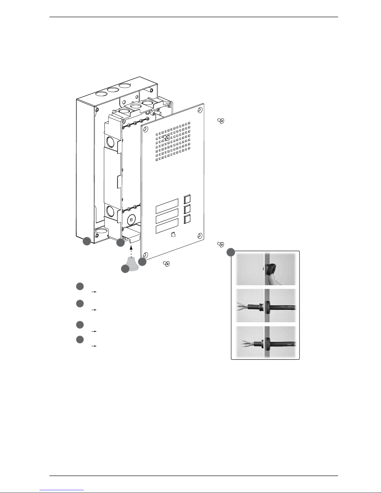
Mounting Surface Mount Kit WSSH 50V
Attention:
The dummy plugs for the surface mount box (in extent of supply) can not be removed without
opening the housing!
3
1
2
4
2
1
4
3
2
..... Front panel (metal) with station electronics
..... Plastic box
Screw the front panel onto the surface mount box
Press the plastic box into the surface mount box
Illustration
front panel
*
..... IP 65 cable feed through
..... Surface mount box (Metal)
Mounting via wall mounting kit
(screws and dowels) – in extent of supply
The cable feed through can be put into the plastic box
after breaking out the expansion openings
(installation cable feed through see picture to the right).
Snap in
Insert cable
Pull back tight
Page 26

Mounting Commend SIP Series
26 2.0/0612
Measurements Rain Protection Roof WSRR 50V
Measurements in mm (inch), not to scale!
164 (6.45) 80 (3.15)
foam strip, approx. 2 mm (0.08 in)
277 (10.9)
Page 27
Commend SIP Series Mounting
2.0/0612 27
Mounting Rain Protection Roof WSRR 50V
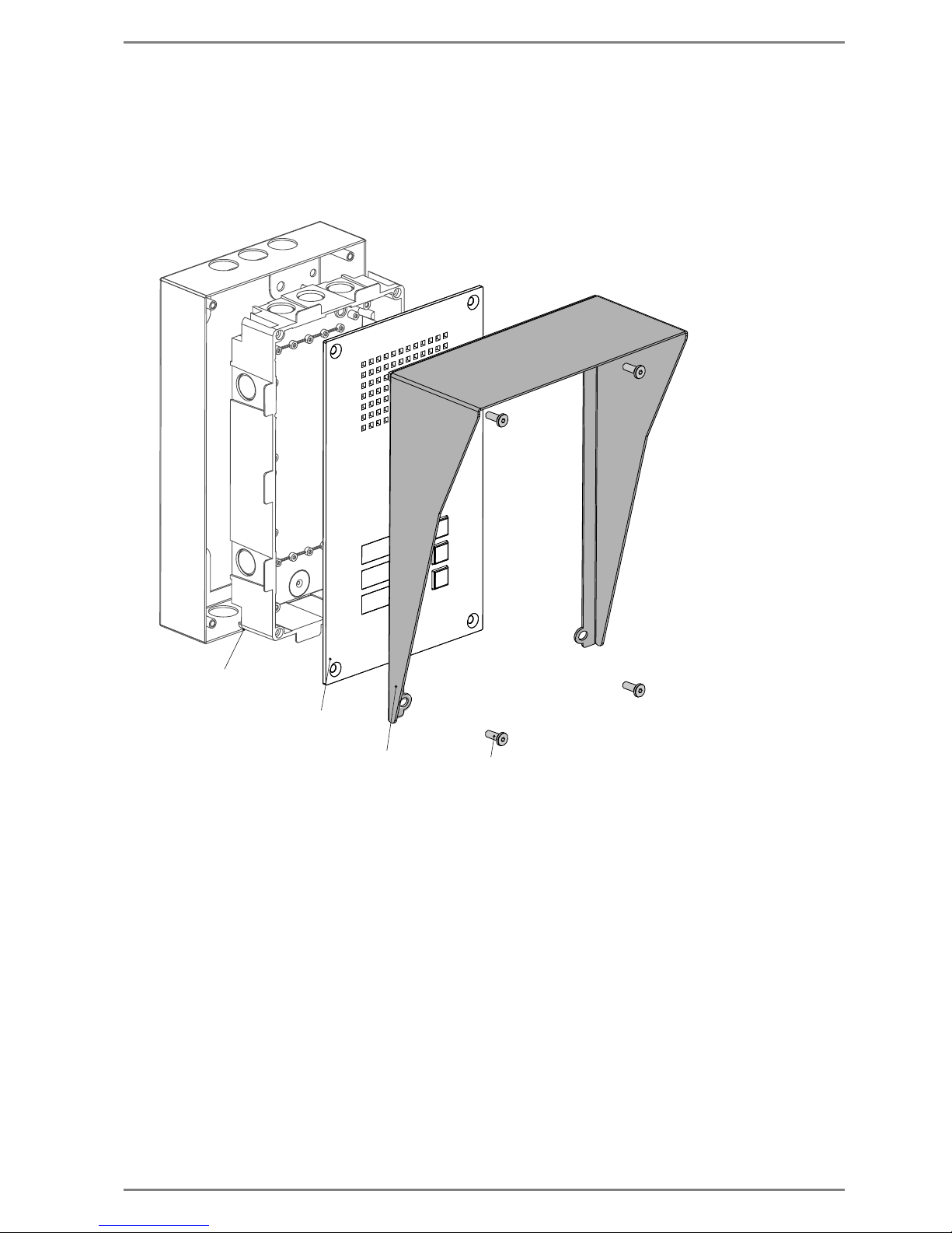
Note:
The rain protection roof can be used for vandal resistant SIP stations in surface mount version and in
flush mount version.
Following illustration shows the installation of the rain protection roof WSRR 50V to the surface mount
kit WSSH 50V.
Remove the screws with which the station front panel is mounted
Afterwards, screw the rain protection roof with the station front panel onto the surface mount box
or the flush mount frame by using the fixing screws in the extent of supply (see above).
Fixing screws required for
WSRR 50V (in extent of supply)
Rain protection roof
WSRR 50V
Front panel (metal) with
station electronics
Example:
Surface mount kit WSSH 50V
Page 28
Mounting Commend SIP Series
28 2.0/0612
SIP Series M
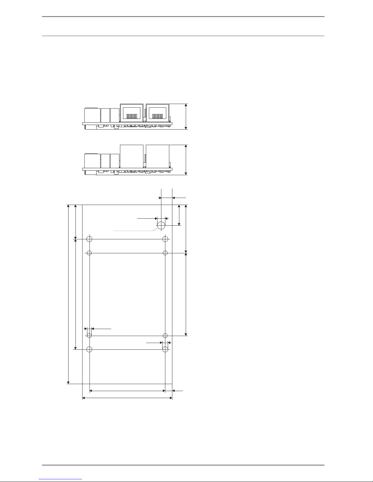
The modules of the SIP Series M are build-in kits for integration in existing housings and panels or
building of customer specific stations.
Measurements SIP-ET 908 / SIP-ET 908-1
Measurements in mm (inch), not to scale!
SIP-ET 908A-1:
SIP-ET 908A:
6.5
ø5.5 (2x)
ø3,2 (4x)
ø4 (4x)
55 (2.17)
65 (2.56)
5
60 (2.36)
35 (1.38)
15 (0.59)
80 (3.15)
25 (0.99)
130 (5.12)
Potentiometer LS
(0.26)
(0.22)
(0.16)
(0.13)
(0.2)
21 (0.83)
18 (0.71)
Page 29
Commend SIP Series Connection
2.0/0612 29
Connection
SIP Series P, SIP Series V, SIP Series VE, SIP Series F
LAN Connection
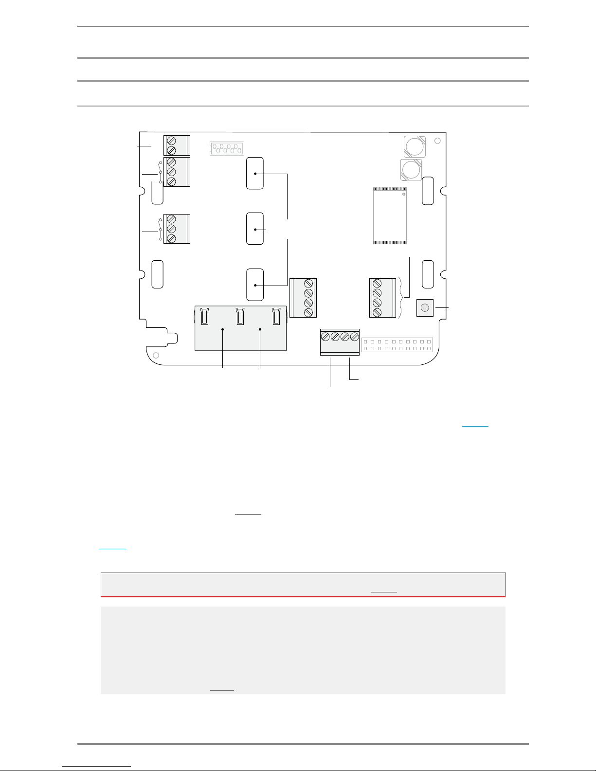
“Ethernet LAN” is connected to the RJ 45 socket “IP Uplink” (see connection diagram above).
Power Supply
For connection of power supply, 2 different possibilities are available:
PoE
The SIP station is supplied via “Power over Ethernet” (Standard IEEE 802.3af) via the RJ 45 socket “IP
Uplink” (see connection diagram above
).
DC–, DC+
If ”PoE” (“Power over Ethernet”) is not available, the SIP station alternatively can be supplied with
“24 VDC 2 V” via the screw terminals “DC–” and “DC+”.
Attention:
For connection of the power supply, the notes and technical data on page 6 have to be observed!
Note:
If both power supply types (i.e. PoE and supply via “DC–,DC+”) are active at the same time, then the
following has to be considered:
In case of a breakdown of the power supply via “DC–,DC+”, and the consequentially take over of PoE,
a reboot of the station is initiated.
In case of a breakdown of PoE, and the consequentially switch-over to power supply via “DC–,DC+”,
the operation of the station will not be interrupted – provided that the 2nd ethernet link (“IP downlink”
see connection diagram above
) is connected to the respective LAN network.
OUT 2
OUT 2
OUT 1
OUT 1
DC+
DC–
IP Uplink
+ PoE
EP+
EP–
EM+
EM–
IN 1
IN 2
IN 3
GND
MUTE
GND
LINE–
LINE+
Alternative
power supply
24 V DC ± 2 V
Slots for inserting
button labels
Factory
Reset
button
IP Downlink
(e.g. IP-camera)
Handset:
Microphone
External Loudspeaker
*relates to:
- SIP-WS20xP
- SIP-WS20xV
- SIP Series VE
*
Page 30

Connection Commend SIP Series
30 2.0/0612
Relay Outputs
The terminals OUT1 / OUT1 as well as OUT2 / OUT2 are operating as relay outputs (changeover
contacts, OUT as make-contact, OUT
as break-contact).
For the available functions of the relay see ”
Relay Configuration” on page 50.
Inputs
Connection of Handset /Headset
It is possible to connect a handset or headset to the terminals “EP+, EP–, EM+, EM–” (see connection
diagram page 29
).
The way the audio output (internal loudspeaker and/or loudspeaker handset/headset) and the audio
feed-in (internal microphone or microphone handset/headset) is carried out at the SIP station, is
defined by means of configuration via the web interface see page 46
.
Connection of an additional Loudspeaker
It is possible to connect an additional loudspeaker (e.g. WSLM 56/WSLM 52) or an amplifier e.g. series
AF to the terminals “LINE+” and “LINE–”. When using loudspeakers of series WSLM 56 or WSLM 52 it
is possible to use also the MUTE function (terminals “MUTE, GND”).
The way audio is put out at simultaneous use of an internal and external loudspeaker (and a handset/
headset), is defined by means of configuration via the web interface see page 46
.
Connection of additional IP Devices
Via the RJ 45 socket “IP Downlink” (see connection diagram on page 29), additional IP devices can be
connected (e.g. IP camera, PC).
Reset Button
Via the reset button a factory reset of the SIP station can be carried out (while rebooting) see page 55.
Slots for Button Labels
Depending on the button version of the station (see page 10), the button labels can be inserted into the
three slots of the PCB.
Attention:
Power supply via PoE is not available via this RJ 45 connection!
GND
IN 3
IN 2
IN 1
IN 3
IN 1
IN 2
It is possible to connect floating contacts to the terminals „IN 1 , IN 2, IN 3,
GND“.
The type of the contacts to be connected (standard input or direct dialling
module) can be defined by means of configuration via the web interface
see page 49
.
Page 31
Commend SIP Series Connection
2.0/0612 31
SIP Series M
LAN Connection
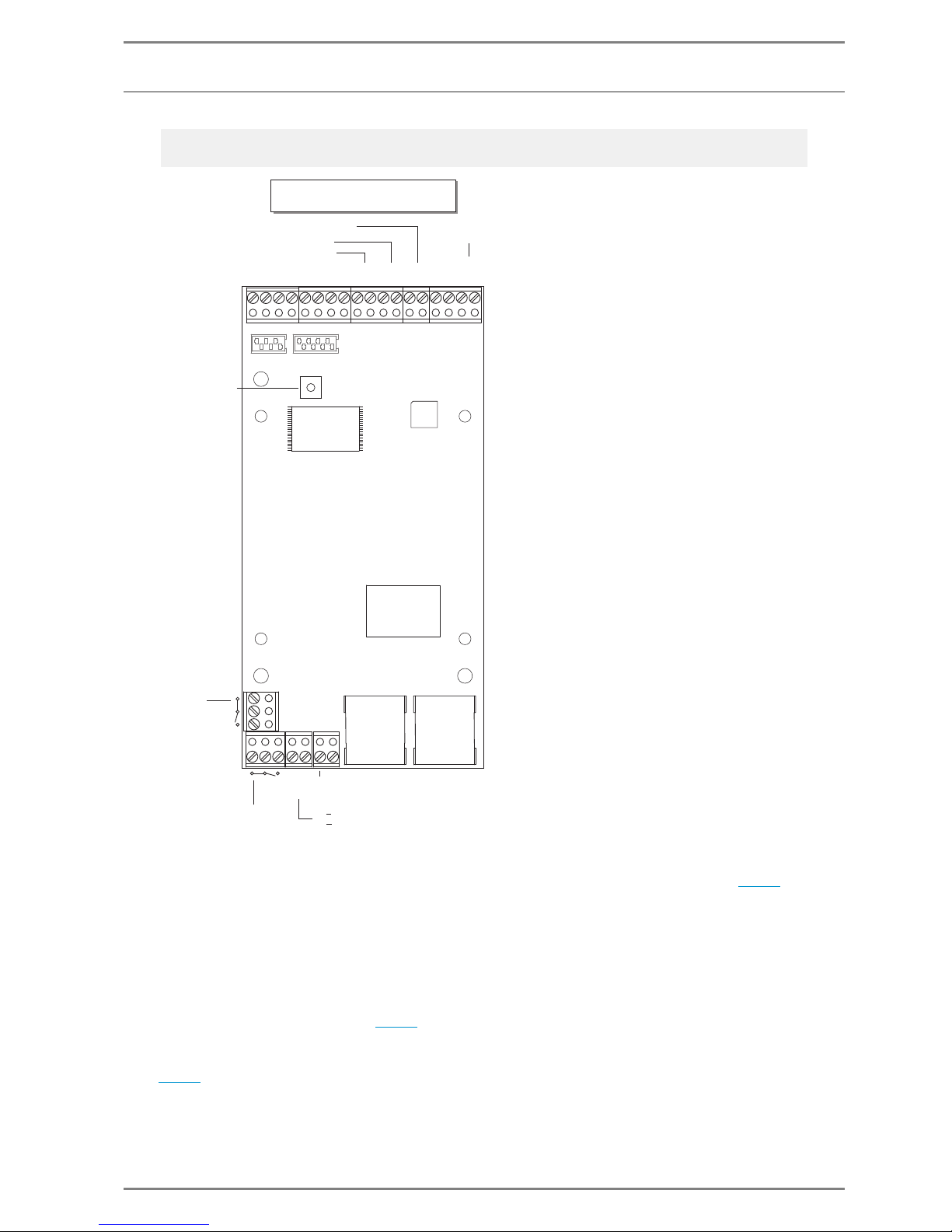
“Ethernet LAN” is connected to the RJ 45 socket “IP Uplink” (see connection diagram above).
Power Supply
For connection of power supply, 2 different possibilities are available:
PoE
The SIP module is supplied via “Power over Ethernet” (Standard IEEE 802.3af) via the RJ 45 socket “IP
Uplink” (see connection diagram above
).
DC–, DC+
If ”PoE” (“Power over Ethernet”) is not available, the SIP module alternatively can be supplied with
“12 – 24 VAC or 15 – 35 VDC” via the screw terminals “PWR1” and “PWR2”.
Note:
The illustration shows a SIP-ET908A; but the connection diagram also applies to the SIP-ET908A-1.
LED
LED+
PWR2
PWR1
OUT1
OUT2
OUT1
OUT2
12
15
IP Uplink
+ PoE
IP Downlink
(e.g. IP-camera)
24 VAC
35 VDC
500 mA
EP+
EP–
EM–
EM+
LS1
LS2
MIC–
MIC+
X0T
GND
GND
IN3
IN2
IN1
Line In
LINE–
LINE +
Microphone
Loudspeaker
Handset:
Loudspeaker 8 or 4 Ohm
ุ
Factory
Reset Button
Connection of Direct Dialling Buttons:
Up to 3 buttons at the terminals
X,0,T
Page 32

Connection Commend SIP Series
32 2.0/0612
Relay Outputs
The terminals OUT1 / OUT1 as well as OUT2 / OUT2 are operating as relay outputs (changeover
contacts, OUT as make-contact, OUT
as break-contact).
For the available functions of the relay see ”
Relay Configuration” on page 50.
Inputs
Connection of Handset /Headset
It is possible to connect a handset or headset to the terminals “EP+, EP–, EM+, EM–” (see connection
diagram page 29
).
The way the audio output (internal loudspeaker and/or loudspeaker handset/headset) and the audio
feed-in (internal microphone or microphone handset/headset) is carried out at the SIP station, is
defined by means of configuration via the web interface see page 46
.
Connection Direct Dialling Buttons
Attention:
For connection of the power supply, the notes and technical data on page 6 have to be observed!
Note:
If both power supply types (i.e. PoE and supply via “PWR1,PWR2”) are active at the same time, then the
following has to be considered:
In case of a breakdown of the power supply via “PWR1,PWR2”, and the consequentially take over of
PoE, a reboot of the station is initiated.
In case of a breakdown of PoE, and the consequentially switch-over to power supply via
“PWR1,PWR2”, the operation of the station will not be interrupted – provided that the 2nd ethernet
link (“IP downlink” see connection diagram on page 31) is connected to the respective LAN network.
GND
IN 3
IN 2
IN 1
IN 3
IN 1
IN 2
It is possible to connect floating contacts to the terminals „IN 1 , IN 2, IN 3, GND“.
The type of the contacts to be connected (standard input or direct dialling module)
can be defined by means of configuration via the web interface
see page 49
.
X
X
0
T
0
T
GND
It is possible to connect up to 3 buttons to the screw terminals “GND, 0, X, T”
(position of the screw terminals see page 31
).
The respective call destination of the single direct dialling buttons 0, X, T is
defined via the web interface see page 39
.
Page 33

Commend SIP Series Connection
2.0/0612 33
Connection Loudspeaker, Microphone
A loudspeaker (4 or 8 ) can be connected to the screw terminals “LS1” and “LS2” (see page 31).
A respective electret- or dynamic microphone can be connected to the screw terminals “MIC–” and
“MIC+” (see page 31
).
Connection of additional IP Devices
Via the RJ 45 socket “IP Downlink” (see connection diagram on page 31), additional IP devices can be
connected (e.g. IP camera, PC).
Reset Button
Via the reset button a factory reset of the SIP module can be carried out (while rebooting) see page 55.
Attention:
Please note that the power output at a loudspeaker with 4 is higher than at a loudspeaker with 8 ;
for technical data see page 6.
Note:
For the exact technical data of the microphone to be connected see page 6
.
Attention:
Power supply via PoE is not available via this RJ 45 connection!
Page 34
Configuration via Web Interface Commend SIP Series
34 2.0/0612
Configuration via Web Interface
The configuration of the SIP station has to be carried out via the integrated web interface.
1st Connection
Establish Connection
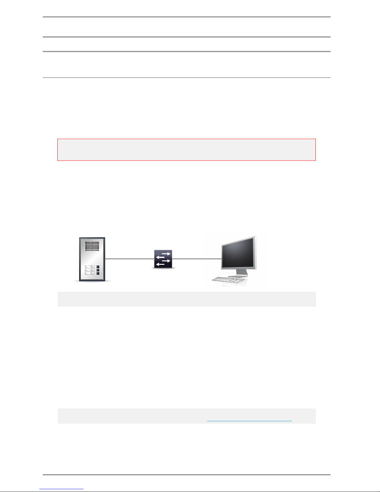
The SIP stations are delivered ex works with a standard IP address, via which the web interface of the
station can be accessed:
IP address 192.168.1.200
Subnet mask 255.255.255.0
If the station can not be used in the local network (LAN) with this IP address, then the following procedure is recommended:
Establish connection between PC and SIP station via a hub (or switch) or via a direct connection
cable.
The PC must be in the same subnet as the SIP station.
This means, an appropriate IP address of that subnet range (e.g. 192.168.1.199) has to be allocated
to the PC temporarily.
Login
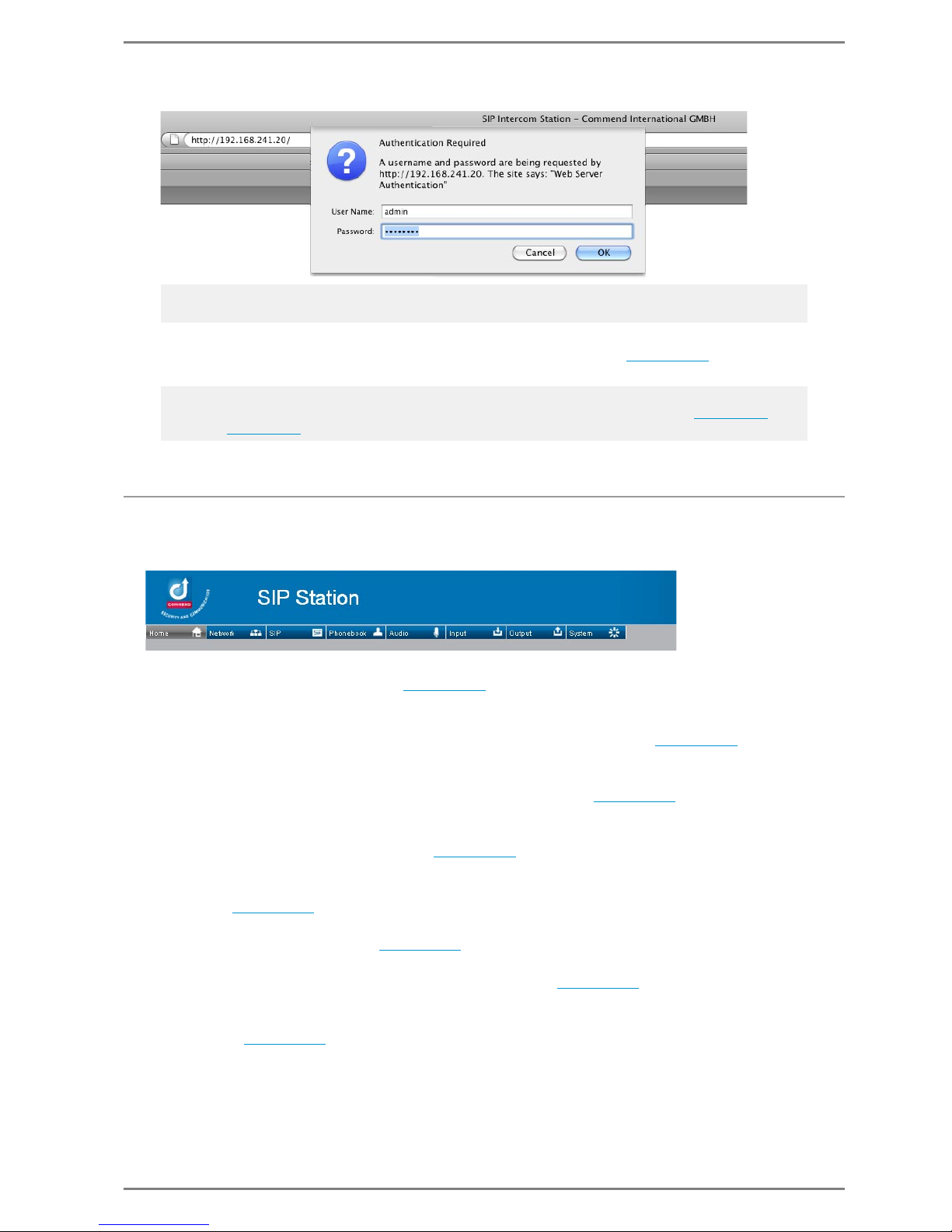
Enter the IP address of the SIP station in the address bar of the respective web browser
It is recommended to use the following web browsers:
Mozilla Firefox min. Version 3.5
Internet Explorer min. Version 8
After entering the IP address, a login dialogue appears where following data has to be entered:
User name
factory default: admin
Password
factory default: commend
Attention:
When connecting the SIP station with this IP-address to the local network (LAN), it is essential to make
sure that this IP-address does not already exist in the network!
Note:
If more stations are configured consecutively, the ARP cache has to be deleted at the PC/notebook.
Note:
It is recommended to change the user name and password see ”
System Settings” on page 53.
Reception
Office
Garage
192.168.1.200 / 24
PC / Notebook:
:
192.168.1.199 / 24
Hub / Switch
e.g.
SIP station:
Page 35
Commend SIP Series Configuration via Web Interface
2.0/0612 35
After successful login the “home” page of the web interface appears (see page 36
).
Configuration of the SIP Station
The web interface of the SIP station provide different tabs, via which the following settings are
possible:
Home:
Overview of configuration settings see page 36
.
Network:
Configuration of the appropriate settings for the network into which the SIP station is integrated, as
well as the required settings for the use of the SNMP and NAT function see page 37
.
SIP:
Configuration of the required settings for the respective SIP provider and/or SIP PBX. Furthermore,
call settings and settings for the LED are configured in this tab see page 39
.
Phonebook:
Configuration of the desired call destinations. It is also possible to configure call chains complete
phonebooks can be created and saved. see page 45
.
Audio:
Configuration of the microphone sensitivity, loudspeaker, echo and noise suppression, pre-recorded
audio etc. see page 45
.
Input:
Configuration of input contacts see page 45
.
Output:
Configuration of relay outputs, e.g. as attendant contacts see page 50
.
System:
System Settings: Modification of user accounts, firmware updates and configuration of the
backlight see page 53
.
SIP Trace: Current log data is displayed.
Note:
The appearance of the login dialogue depends on the used web browser.
Note – Factory Reset:
It is possible, to reset all settings carried out via the web interface, to factory default (see page 34
) –
therefore see page 55.
Page 36
Configuration via Web Interface Commend SIP Series
36 2.0/0612
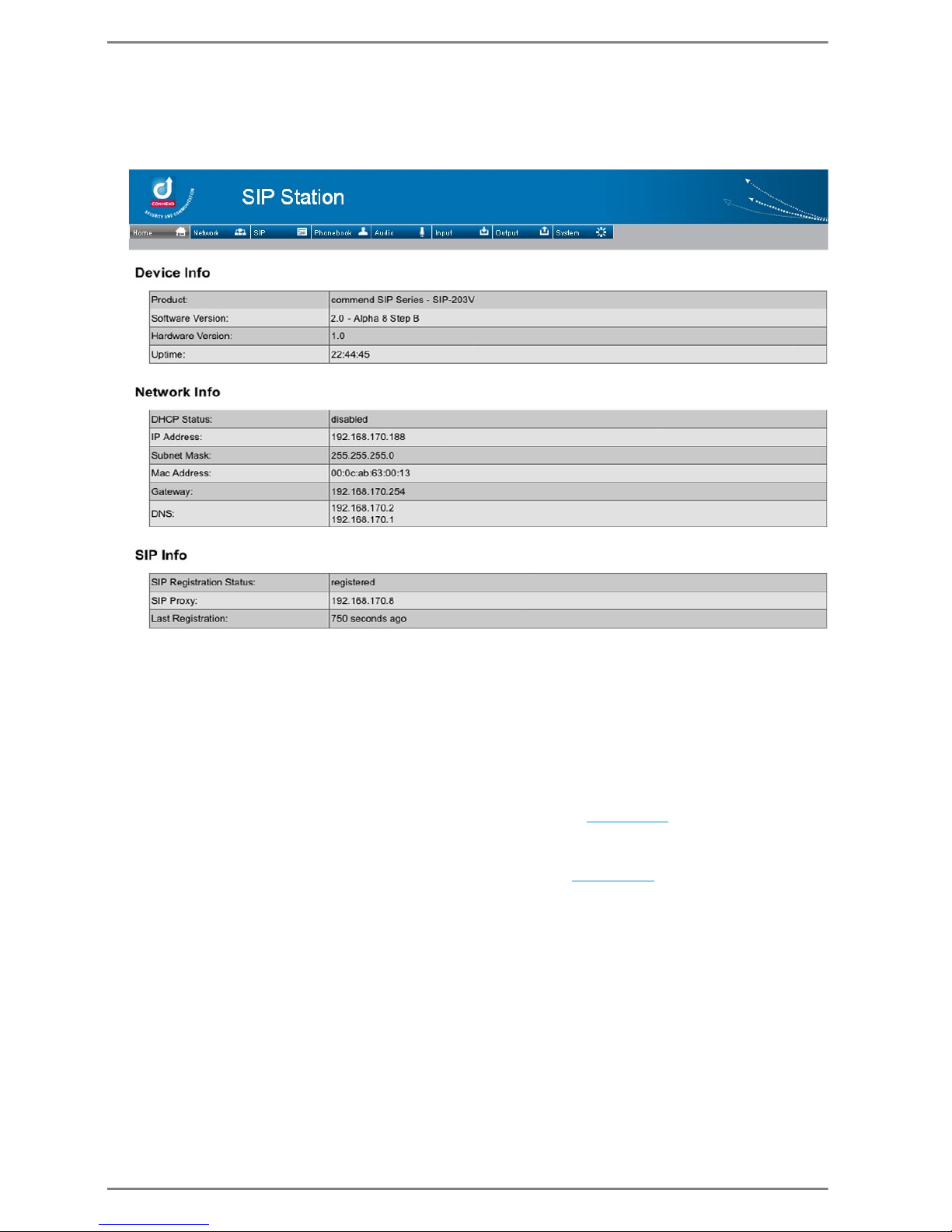
Overview Configuration Settings
The home page provides an overview of the current software and hardware versions and configuration
settings of the SIP station – the data is only informative, i.e. no configuration can be carried out via this
page.
Device Info
In the first section the following device information is indicated:
The type designation of the SIP station.
The software and hardware version of the SIP station.
The time period the SIP station is already in operation.
Network Info
In this section the network settings configured at tab Network (see page 37) are indicated.
SIP Info
In this section the relevant SIP settings configured at tab SIP (see page 39) are indicated.
Page 37
Commend SIP Series Configuration via Web Interface
2.0/0612 37
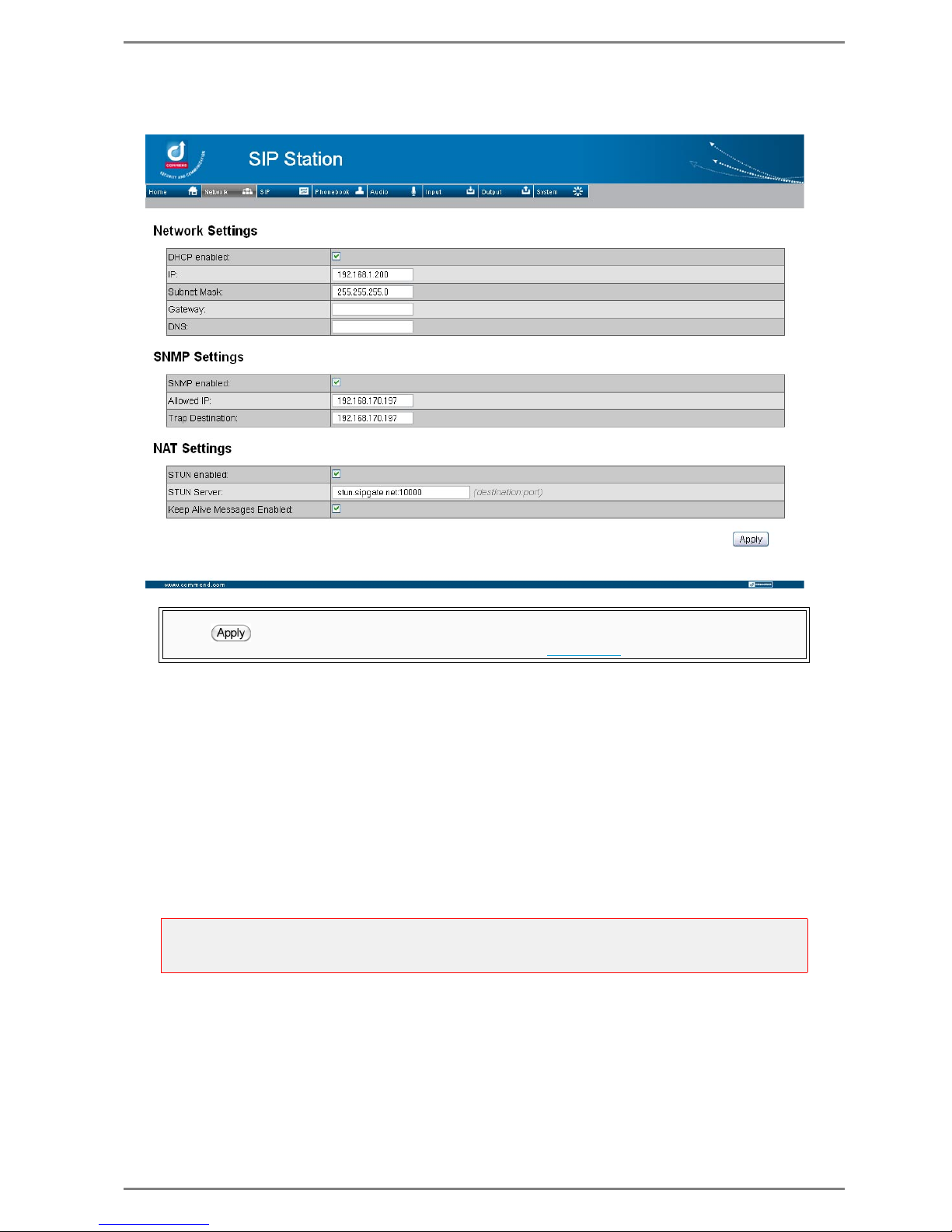
Network Settings
Select tab Network – following dialogue is indicated:
DHCP enabled: If the checkbox is activated, the required IP settings (i.e. the described settings
below) will be requested from a DHCP server automatically after reboot.
This also means, that the settings made in the fields IP, Subnet Mask, Gateway, DNS have no
effect on the running configuration.
IP: The IP address is assigned manually –
required only, if DCHP is deactivated.
Subnet Mask: The appropriate subnet mask is entered manually –
required only, if DCHP is deactivated.
Gateway: The IP address of the router or standard gateway is entered manually –
required only, if DCHP is deactivated.
DNS: The IP address of the DNS server is entered manually –
required only, if DCHP is deactivated.
Any modifications made in the fields are taken over in the running configuration as soon as the but-
ton (at the bottom right) is clicked and a reboot has been made.
The reboot has to be carried out manually at tab System see page 53.
Attention:
Changes of these settings may not be carried out without the permission of the system administrator!
Incorrect IP settings may lead to network instabilities!
Page 38

Configuration via Web Interface Commend SIP Series
38 2.0/0612
SNMP Settings
In the section SNMP Settings the settings required for the use of the monitoring function via the
“Simple Network Management Protocol” are entered.
SNMP enabled: With activation of the checkbox, the SNMP function is activated.
Allowed IP: The IP address of the PC to be authorised for monitoring the SIP station, has to be
entered (so called “management station”).
Trap Destination: The IP address of the PC to which “traps” (station messages) shall be sent, has
to be entered.
NAT Settings
In the section NAT Settings the settings required for the use of the SIP devices behind a NAT, are entered.
STUN enabled: With activation of the checkbox, the STUN function is activated.
STUN Server: Entering the IP address incl. port of the “STUN server”: <IP>:<Port> (e.g. stun.sip-
gate.net:10000).
Keep Alive Messages Enabled: With activation of the checkbox, “dummy” data packages will be
sent regularly to the SIP Server to keep the connection over NAT open.
Note:
The definition and use of the function is explained at ”SNMP” on page 58.
WHAT IS STUN?
Session Traversal Utilities for NAT is a network protocol, i.e. a client-server protocol based on UDP, for
detecting firewalls and NAT routers and to traverse NAT routers.
STUN detects the current IP address of the connection. Thus, e.g. a SIP telephone can detect and communicate its own current IP address. This is important, in order the conversation partner is able to address its
conversation data correctly.
Therefore, a request to a server (“STUN server”) is sent. The answer of the server includes a public “IP
address”, i.e. the IP address and the sender UDP port of the SIP device (“client”). This address is coded
with a XOR mask, to avoid a translation of the address via a NAT router.
Note:
These dummy packages are sent constantly, i.e. no matter if actions are carried out at the station.
Page 39
Commend SIP Series Configuration via Web Interface
2.0/0612 39
SIP-, Call- and LED Settings
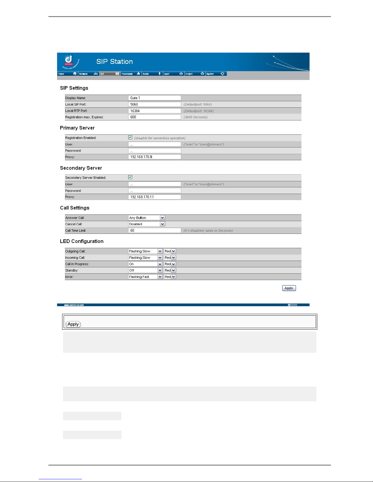
Select tab SIP – following dialogue is indicated:
SIP Settings
In this section, the general settings enabling a communication via SIP, have to be configured.
Display Name: An optional text (“Caller-ID”) for the SIP station can be entered.
Local SIP Port: Here the port for the SIP protocol can be changed.
Local RTP Port: Here the UDP port for the RTP protocol can be changed.
Any modifications made in the fields are taken over in the running configuration as soon as the button
(at the bottom right) is clicked. This may take a couple of seconds.
Note:
The information put in parentheses (next to the appropriate fields) represent standard values or support
for configuration.
Note:
The display name may not contain any special characters and not more than 200 digits.
Standard: 5060
Standard: 16384
Page 40

Configuration via Web Interface Commend SIP Series
40 2.0/0612
Registration max. Expires: Here the timer is set, which is responsible for the update of the regis-
tration of the station at the SIP server. I.e. the entered time in seconds is sent by the SIP station to
the SIP server (Proxy see below
). The server is sending an acknowledge or alternate time interval
back, which will then be set and used immediately. I.e. within this time interval the registration of the
SIP station at the SIP server will be updated regularly.
Server Settings
In the section Primary Server, settings required for the connection to a SIP server, have to be configured.
Registration Enabled: If this checkbox is activated, the SIP station tries to register (with the appro-
priate User and Password) at the SIP server specified at Proxy (see below).
User: The call number of the SIP station for the SIP registration has to be entered, i.e. the call
number of the corresponding SIP account on the SIP server.
Password: The corresponding password (defined at the SIP server) for the SIP registration has to
be entered (required for authentication).
Proxy: The IP address or URL of the appropriate SIP server to which a connection shall be establis-
hed (i.e. at which the SIP station shall be registered).
Additional Server
In the section Secondary Server, a connection to an additional SIP server can be configured. Thus a
better reliability of the appropriate SIP station is achieved (e.g. if the connection to the primary server
is lost, the SIP station can still be reached via the secondary server).
Secondary Server Enabled: With activation of this checkbox, the connection to a second server is
enabled. I.e. the SIP station tries to register (with the respective User and Password) at the SIP server, which is entered at Proxy.
User / Password / Proxy: see above
Call Settings
In this section, the settings required for establishing a call, have to be configured.
Answer Call: Combo-box for configuration of the call acceptance.
Menu items:
Autoanswer: An incoming call is accepted without any ringing and without pressing any button.
Button <x>: The call is not accepted until the corresponding button of the SIP station is pressed.
Any Button: The call can be accepted via pressing any button of the SIP station (however it has
to be pressed one button).
Cancel Call: Combo-box for configuration of how a running conversation (between two SIP de-
vices) shall be cancelled.
Standard: 3600 sec.
Note:
The registration is updated 60 seconds before the timer expires (but not less than 40 seconds).
Note:
In case of operation without server, this checkbox has to be deactivated.
Note:
For some SIP servers it may be required to enter additionally the domain
“user name@domain”.
Note:
The number and the labelling of the buttons in the drop-down menu depends on the used station version (see page 10
) and the number of configured direct dialling modules in use (see page 49).
Page 41

Commend SIP Series Configuration via Web Interface
2.0/0612 41
Menu items:
Disabled: A running conversation can not be cancelled at the SIP station (i.e. only at the respec-
tive remote station).
If a “Call Time Limit” is configured (see below), then the conversation is cancelled automatically after this defined time.
Button <x>: Besides the “Call Time Limit” the conversation can only be cancelled with the cor-
responding button at the SIP station.
Any Button: Besides the “Call Time Limit” the call can be cancelled via pressing any button of
the SIP station.
Call Time Limit: Time in seconds, after which a running conversation (between two SIP devices) is
cancelled automatically.
If the “call time limit” shall be deactivated, then “0” has to be entered.
Allow Arbitrary Dialing: If the checkbox is activated, it is possible to dial any desired number. I.e.
it is possible to dial a number which is not saved in the ”
Phonebook” (if the checkbox is deactivated,
only call destinations saved in the phonebook can be dialled).
As soon as the number is entered, the Enter button has to be pressed, in order to set up the call.
LED Configuration
In this section, settings for the LED behaviour for the following states can be configured:
Outgoing Call – Outgoing call from the SIP station
Incoming Call – Incoming call from the SIP station
In Call – Running conversation between two SIP devices
Standby – Idle state (inactivity) of the SIP station
Error – Error in connection to SIP server, signalling or other problems
Following settings regarding LED behaviour (for the states listed above) are possible:
On: LED is permanently on
Off: LED is permanently off
Flashing:Fast: LED blinks in a fast rhythm
Flashing:Slow: LED blinks in a slow rhythm
Note:
The feature is very useful for emergency situations, where e.g. only the emergency center shall be
able to cancel the call – so it is ensured that the initiator of the emergency call can not cancel the call
unintentionally.
Note:
The number and the labelling of the buttons in the drop-down menu depends on the used station version (see page 10
) and the number of configured direct dialling modules in use (see page 49).
Note:
This feature only refers to stations with full keypad and registration at a SIP server. At serverless
operation no arbitrary dailing is possible.
Note:
Idle state = registered at SIP server or in case of operation without server: “ready for operation”.
Note:
The LED (currently) can indicate the colour RED only.
Page 42
Configuration via Web Interface Commend SIP Series
42 2.0/0612
Phonebook Settings
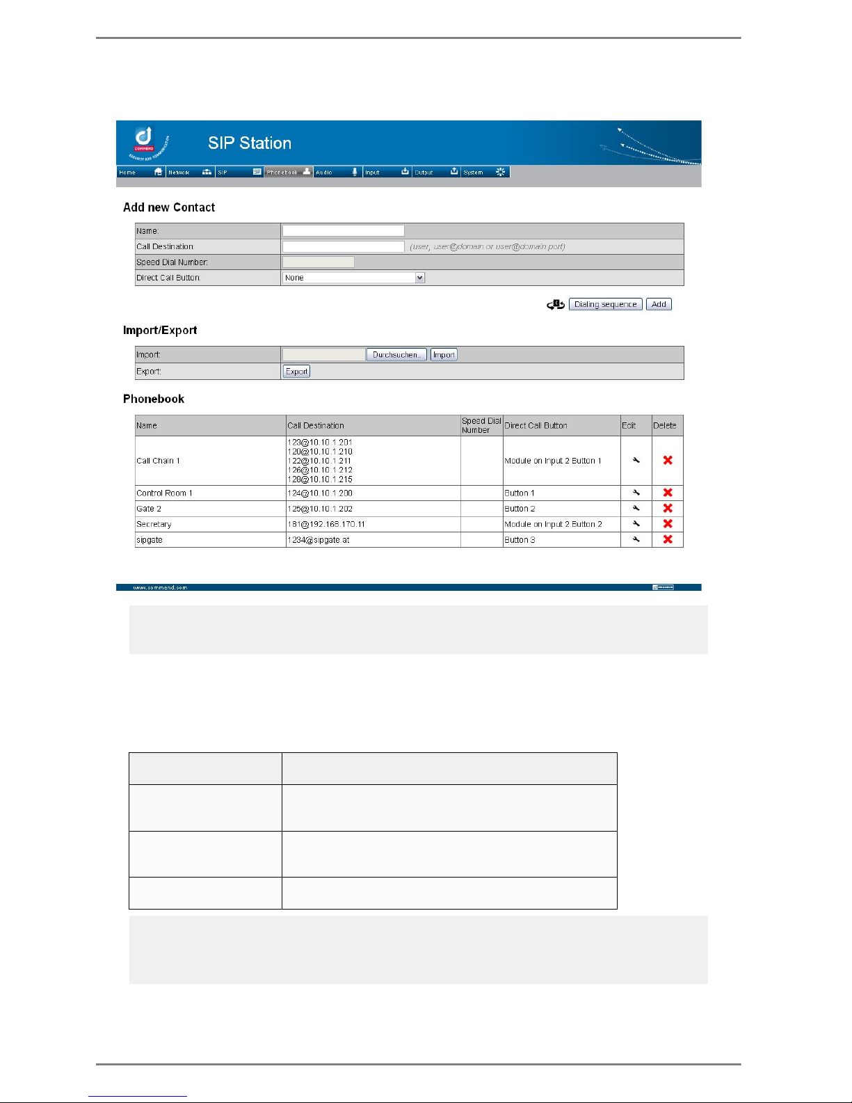
Select tab Phonebook – following dialogue is indicated:
Configuration Call Destinations
In the section Add new Contact the desired call destinations are added.
Name: Here an optional name for the call destination can be entered.
Call Destination: In this field the respective call destination is entered.
Note:
The information put in parentheses (next to the appropriate fields) represent standard values or support
for configuration.
user@server address
user...call number of the respective call destination
server address...IP address or host name of the SIP Server
E.g.: [email protected]
When the respective button of the SIP station is pressed,
the station dials number “307” and sends the number to
the SIP server “192.168.170.8”.
E.g.: [email protected]
When the respective button of the SIP station is pressed,
the station dials number “1234” and sends the number to
the SIP server “sipgate.at”.
user@proxy:port - E.g.:
[email protected]:5061
It is also possible to enter the port additionally (optional)
Note:
If a SIP station is called, and the call is not acknowledged within 60 seconds, then this non-acceptance
is indicated to the caller and the call potentially has to be initiated again.
Entering a port is only required for serverless operation <user.domain:port>
Page 43
Commend SIP Series Configuration via Web Interface
2.0/0612 43
Speed Dial Number: When using a SIP station with full keypad, a direct dialling number can be
entered here for dialling the respective call destination.
Direct Dialling Button: Selection of the direct dialling button for the call destination.
With click on the button Add, the entered call destination (i.e. the entry) is added to the ”
Phonebook”
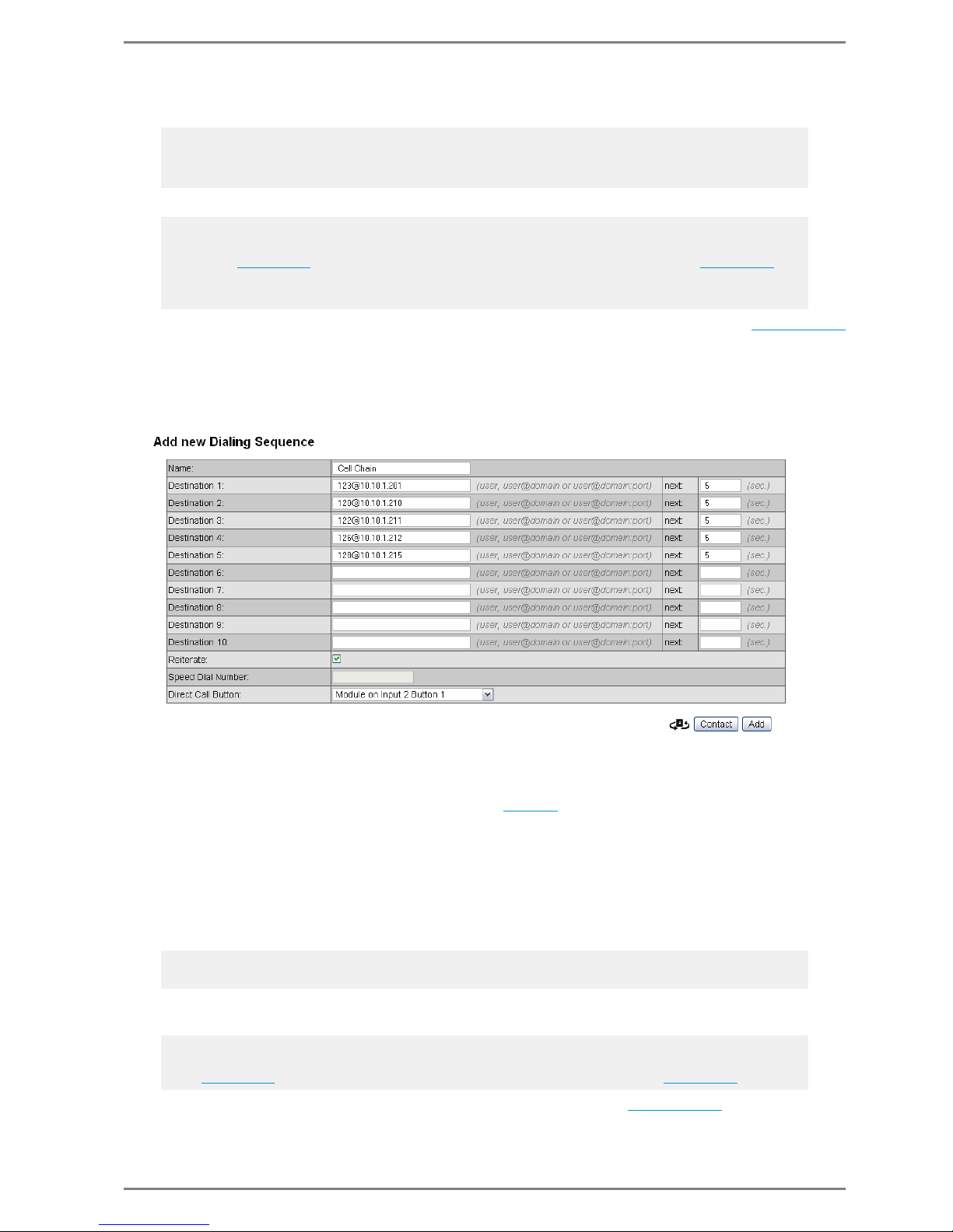
Configuration Call Chain
With click on the button Dialing sequence the input mask for configuration of a call chain is opened.
I.e. the call is taken over within a configurable time period, the call is forwarded to the appropriate call
destinations.
Name: Here a name for the call chain can be entered.
Destination x: In the fields up to 10 call destinations can be entered, which are dialled auto-
matically, if the call is not taken over within a definable time (see field next).
The call destinations are entered as described on page 42
.
next: Here the time in seconds is entered, after which the next call destination of the sequence is
dialled (if the call is not accepted).
Reiterate: If the checkbox is activated, the call chain will be started once again from Destination
1, after the last call destination has been reached. This process will be repeated until the call is taken
over ( infinite loop).
Speed Dial Number: When using a SIP station with full keypad, then here a direct dialling number
for dialling the respective call destination (and therewith the call chain) can be entered.
Direct Call Button: Here the button for direct dialling the respective call destination (and thus the
call chain) can be selected.
With click on the button Add, the entered call chain is added to the ”
Phonebook”.
Note:
For 1-,2-,3-button versions this field has no function.
Besides the buttons 0–9 it is also possible to use the button T for direct diallings (e.g. T1, T3...)
Note:
The number and the labelling of the buttons in the drop-down menu depends on the used station
version (see page 10) and the number of configured direct dialling modules in use (see page 49).
When using a handset, it is possible to select “Handset offhook”. Via this feature it is enabled, to dial
the number of the respective call destination by simply going off-hook.
Note:
For 1-,2-,3-button versions the field has no function.
Note:
The number and the labelling of the buttons in the drop-down menu depends on the used station version (see page 10) and the number of configured direct dialling modules in use (see page 49).
Page 44

Configuration via Web Interface Commend SIP Series
44 2.0/0612
With click on the button Contact the input mask for entering single call destinations is indicated
again see page 42
.
Import/Export Phonebooks
In the section Import/Export it is possible to save and import phonebooks.
Import: With click on the button to the right of the field, a dialogue for loading a file is opened. Here
a already created phonebook (.csv) can be selected.
With click on the button Import the selected file is imported, i.e. loaded.
Export: With click on the button Export the current Phonebook is exported, i.e. saved as .csv file in
the local network.
Phonebook
In the section Phonebook the entered call destinations and call chains are listed.
Name / Call Destination / Speed Dial Number / Direct Call Button: Here the configured data
in the input masks Add new contact (see page 42
) and Add new dialing sequence (see page 43)
are displayed.
Edit: With click on the symbol the respective entry is indicated in the appropriate input mask and
thus can be edited.
Delete: With click on the respective entry is deleted.
Attention:
If a previously saved phonebook (e.g. phonebook.csv) is loaded, then this .csv file overwrites the current
entries in section Phonebook!
Page 45
Commend SIP Series Configuration via Web Interface
2.0/0612 45
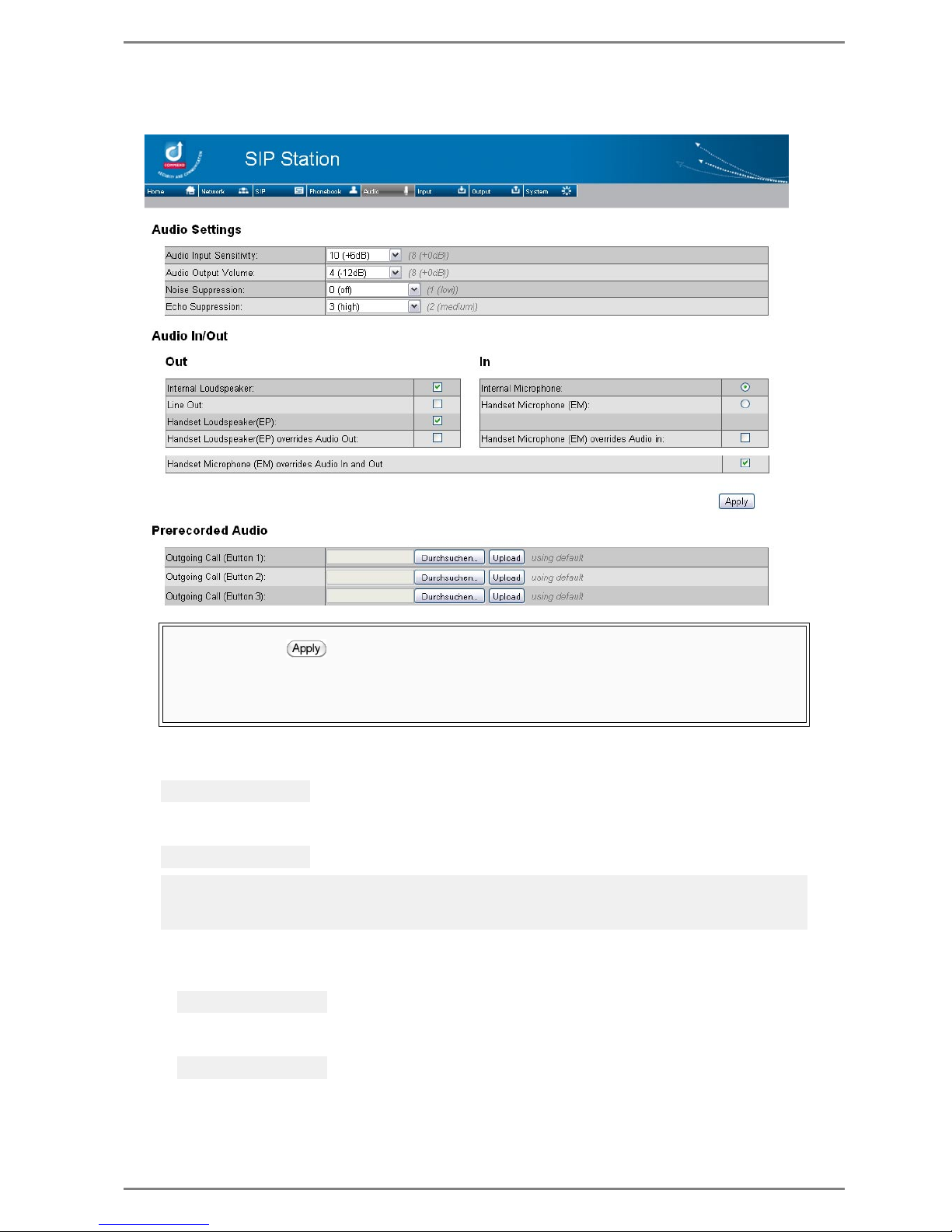
Audio Settings
Select tab Audio – following dialogue is indicated:
Mic Sensitivity: Configuration of the desired sensitivity of the (connected) microphone of the SIP
station in 7 levels (–12 dB to +6 dB).
Speaker Volume: Configuration of the desired volume level of the (connected) loudspeaker of the
SIP station in 13 levels (–24 dB to +12 dB)
Noise Suppression: Configuration of the background noise suppression in 5 levels:
Minimum level “1 (low)” to maximum level “4 (maximum)”.
If no background noise suppression shall be used, then “0 (off)” has to be selected.
Echo Suppression: Configuration of the acoustic echo canceller (AEC) in 5 levels:
Minimum “Echo Cancelling” level “0 (minimum)” to maximum level “4 (maximum)”
Any modifications made in the “Audio Settings” fields are taken over in the running configuration as
soon as the button (at the bottom right of the section “Audio Settings”) is clicked.
Modified values in the fields Mic Sensitivity and Speaker Volume become active immediately du-
ring a running conversation.
Modified values in the fields Noise Suppression and Echo Suppression become active not before
the next conversation.
Default: 0 dB
Default: 0 dB
Note:
The configured level defines the volume of the ring tone (at an incoming call) as well as the volume of
the different signal tones.
Default: 1 (low)
Default: 2 (medium)
Page 46

Configuration via Web Interface Commend SIP Series
46 2.0/0612
Audio In/Out
In the section Audio In/Out the configuration of the audio output and audio feed-in is carried out:
Internal Loudspeaker: If the checkbox is activated, the audio signal is put out via the internal loud-
speaker.
Line out: If the checkbox is activated, the audio signal is put out via the terminals “Line+” and
“Line–” (connection possibility for an external loudspeaker see page 29
).
Handset Loudspeaker(EP): If this checkbox is activated, then the audio signal is put out via the
terminals “EP+” und “EP–”, i.e. via the loudspeaker of the handset/headset (see page 29
).
Handset Loudspeaker(EP) overrides Audio Out: If this checkbox is activated, then the audio si-
gnal is put out only via the terminals “EP+” and “EP–” as soon as a handset/headset is connected
(even if Handset Loudspeaker(EP) is not activated). This also means, even if Internal Loud-
speaker and Line out are activated, the audio signal will only be put out at the connected handset/
headset.
Internal Microphone: If the option field is activated, audio is fed-in only via the internal micro-
phone (i.e. terminals “EM+” and “EM–” for microphone of the handset/headset are deactivated).
Handset Microphone (EM): If the option field is activated, audio is fed-in only via the terminals
“EM+” and “EM–”, i.e. via the microphone of the handset/headset (the internal microphone is deactivated).
Handset Microphone (EM) overrides Audio in: If the checkbox is activated, then the audio signal
is fed-in only via the terminals “EM+” and “EM–” as soon as a handset/headset is connected (even
if Handset Microphone(EM) is not activated). This also means, even if Internal Microphone and
is activated, the audio signal will only be fed-in via the microphone of the connected handset/headset.
Handset Microphone (EM) overrides Audio In and Out: This checkbox is required for the hand-
set/headset, which can be detected (by the respective SIP device) via the microphone input only, like
the handset WSSH 50P.
I.e. if the audio signal shall be put out only via the terminals “EP+” and “EP–” when using a
WSSH 50P (as described at Handset Loudspeaker(EP) overrides Audio Out above
), then this
checkbox has to be activated. Additionally to that, audio will be fed-in via the terminals “EM+” and
“EM–” as described at Handset Microphone (EM) overrides Audio In above
.
Pre-Recorded Audio
In this section, audio files (pre-recorded audio) can be loaded into the memory of the SIP station:
Attention:
For changing the default values of the microphone sensitivity / volume level (in particular for conversations between 2 SIP stations), in combination with changes of the values for the noise and echo
suppression, the information regarding audio configuration on page 62
shall be read previously.
Attention:
This function is not available for the SIP Series M.
The terminals “Line +” and “Line –” function for devices of the SIP Series M as “Line In”. I.e. the terminals can be used for feed-in of audio (e.g. music, radio conference).
Attention:
This function is not available for the handset WSSH 50P. If the audio signal shall be put out via the
loudspeaker of the handset WSSH 50P – as soon as the handset is connected – then the checkbox
Handset Microphone (EM) overrides Audio In and Out has to be activated see below.
This also applies to handsets/headsets. which can only be detected via the microphone input.
Memory: max. 60 seconds
Audio format:
Accepted:
WAV / 8– 48 kHz
8, 16 bit / mono, stereo
Recommended:
WAV / min. 16 kHz
16 bit / mono
Attention:
One single WAV file may not exceed the file size of 5 MB!
Page 47

Commend SIP Series Configuration via Web Interface
2.0/0612 47
Pre-recorded audio can be used for the following states:
Outgoing Call Destination <x> – Outgoing call from the SIP station, initiated via the respective
button (e.g. 0, T or X).
The audio file can be configured e.g. as calm down message at call initiation or as individual call
tone for the call initiator.
Incoming Call – Incoming call to SIP station.
The audio file can be configured as individual calling signal (and/or ring tone).
Error – Error in establishing a call (e.g. call destination can not be reached or registration not carried
out etc.).
Pre-recorded audio can be used e.g. as acoustic signal for line fault
Location Message – The called SIP device (e.g. mobile phone) receives a location message as infor-
mation where (i.e. from which SIP device) the call comes from.
Loading Pre-recorded Audio:
In the desired line click on the 1st button to the right of the blank field (“Browse...”)
In the appearing dialogue select the desired audio file
Via the button Upload the selected audio file is loaded into the station.
Note:
The labelling and the number of the “call destination” fields depends on the used station version
(1-,2-,3-button version see page 10
).
Note:
In order that the calling signal (ring tone) is put out at the station, “Autoanswer” may not be configured for call acceptance see page 40
.
Note:
The labelling of the button depends on the used browser and operating system.
Note:
Uploading, recoding and saving the audio file can take some seconds:
Loading time = 2 x file length;
E.g. file with 10 seconds: loading time = 2 x 10 = 20 seconds
All audio files together may not exceed the max. length of 60 seconds see page 46.
Page 48
Configuration via Web Interface Commend SIP Series
48 2.0/0612
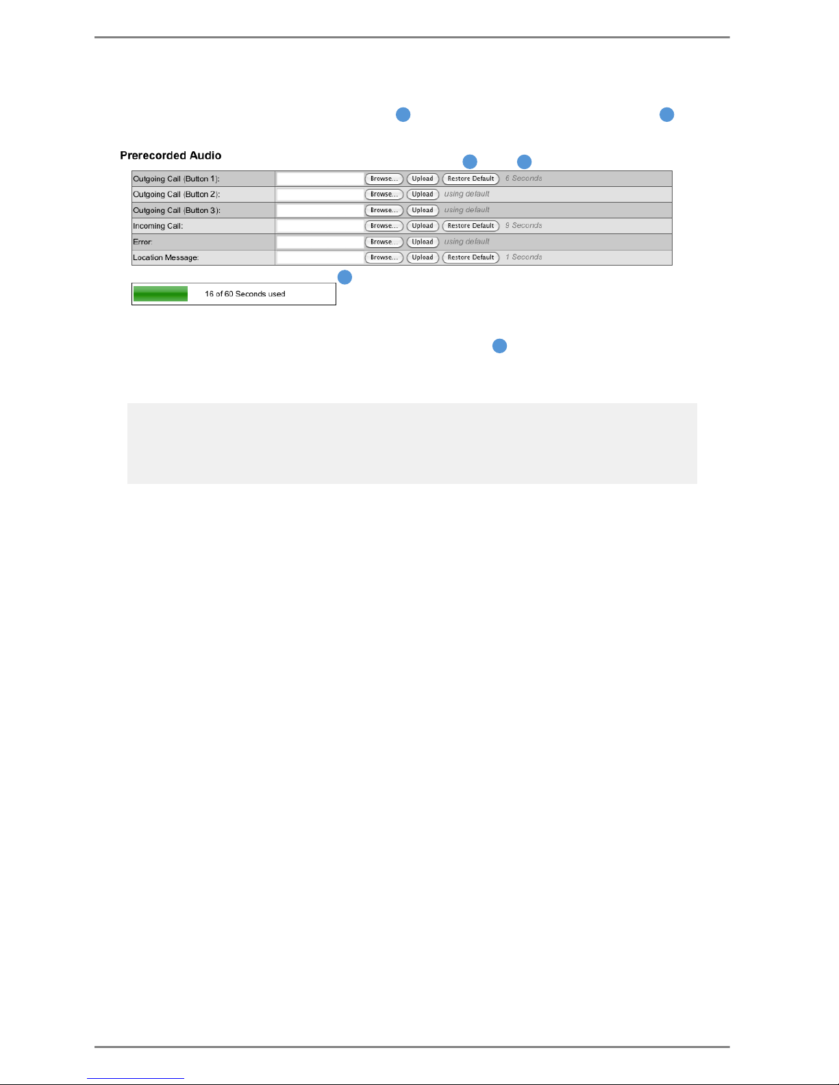
Indication of the file length:
If the desired audio files are loaded into the memory of the SIP station, the length of the respective
audio file is displayed in the appropriate line ( ) and the total length of all loaded files ( ) are displayed in the bar below the fields in the section “Prerecorded Audio”.
Remove Loaded Audio Files from Memory:
In case of a loaded audio file, the button Restore Default ( ) is indicated in the respective line.
Click on this button to remove the previously loaded audio file from the memory; the respective state
will then be reset to the default settings.
Note:
Default setting for “Incoming Call” and “Outgoing Call (Button <x>)” means, that the factory default
tones become active again.
Default setting for “Error” and “Location Message” means, that no signal tones are put out for these
states.
2 3
2
3
1
1
Page 49
Commend SIP Series Configuration via Web Interface
2.0/0612 49
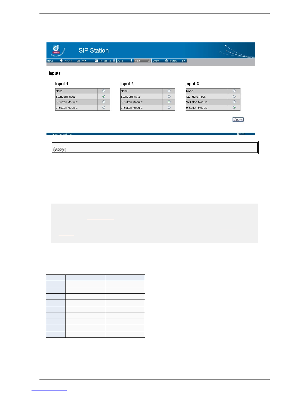
Input Configuration
Select tab Input – following dialogue is indicated:
Configuring Inputs
In the sections Input 1 to Input 3 separately for all 3 inputs of the SIP station, the following option
fields are available:
None: The respective input is deactivated (connected contacts can not be used).
Standard Input: The input is activated for potential-free contacts (but no input level detection).
3-Button Module: The input is activated for use of the direct dialling module WSDD 53V.
9-Button Module: The input is activated for use of the direct dialling module WSDD 59V.
Resistance Values for customer specific input circuits
Instead of using the direct dialling modules WSDD 53V and WSDD 59V, it is possible to create individual resistance circuits for input contacts, to which the desired buttons can be connected.
Following table shows the appropriate resistance values for the respective buttons 1 – 9:
Any modifications made in the fields are taken over in the running configuration as soon as the button
(at the bottom right) is clicked. This may take a couple of seconds.
Note:
If a button of the direct dialling module WSDD 53V/WSDD 59V is configured for dialling a call des-
tination in the ”Phonebook”, then the respective direct dialling module can not be deactivated.
Therefore, another button has to be configured for the respective call destination or for the respective
call chain in the phonebook (or the entry in the phonebook has to be deleted), see page 42
and
page 43
.
Input contacts can only be used for call initiation (i.e. no call acknowledge, delete call...)
Button Range [] Value []
1 0 – 260 100
2 270 – 760 560
3 770 – 1k2 1k
4 1k3 – 2k1 1k5
5 2k2 – 3k7 2k7
6 3k8 – 5k6 4k7
7 5k7 – 7k4 6k0 (3k3 + 2k7)
8 7k5 – 11k3 8k2
9 11k4 – 20k 12k4 (6k8 + 5k6)
Page 50
Configuration via Web Interface Commend SIP Series
50 2.0/0612
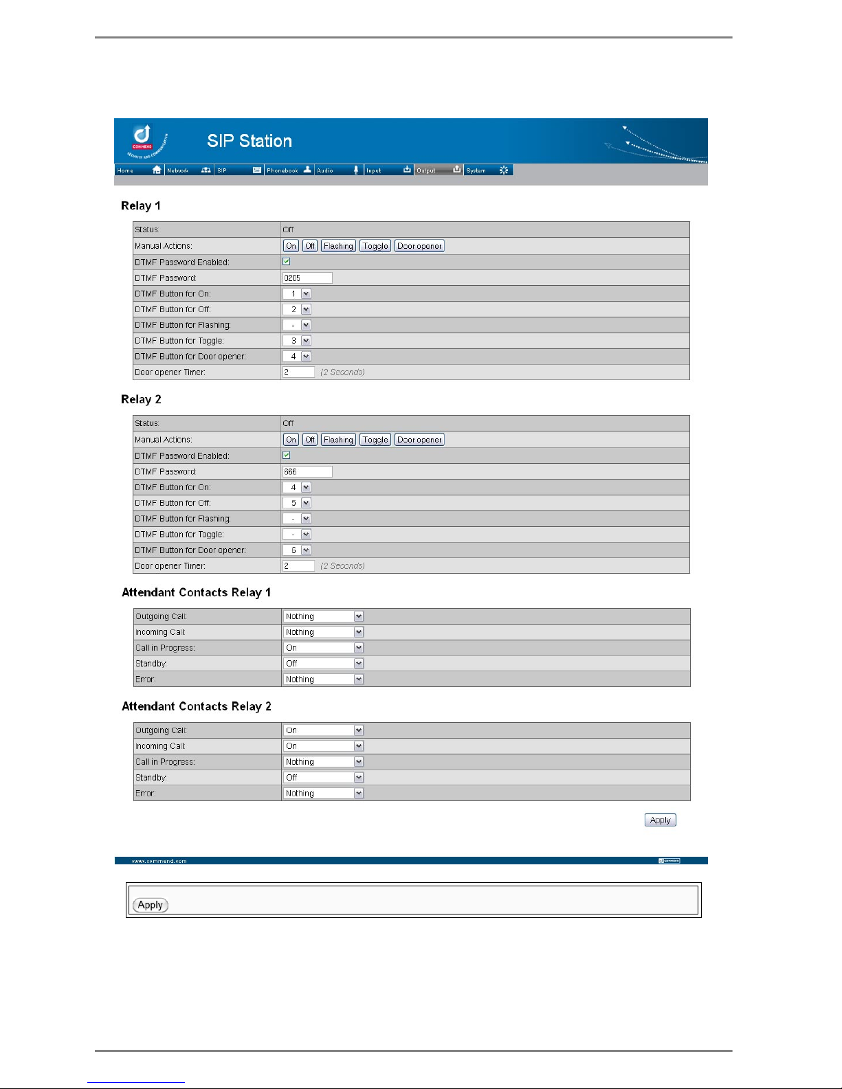
Relay Configuration
Select tab Output – following dialogue is indicated:
Any modifications made in the fields are taken over in the running configuration as soon as the button
(at the bottom right) is clicked. This may take a couple of seconds.
Page 51

Commend SIP Series Configuration via Web Interface
2.0/0612 51
Configuring Relays
In the sections Relay 1 and Relay 2 the following settings can be configured separately for both relays
of the SIP station:
Status: Indication of the current relay status.
Manual Actions: Clicking on the buttons in this row triggers the following relay actions directly
from the web interface:
On: Close relay output (activate)
Off: Open relay output (deactivate)
Flashing: Switch relay output to blinking (switch on and off in rhythm of one second)
Door opener – door opener function: relay output is closed for a definable time (see below “Door
opener Timer”).
Toggle: Invert current state of the relay output (switch on/off)
DTMF Password Enabled: If the checkbox is activated, a password has to be entered at the SIP
telephone, (see DTMF Password), in order to be able to trigger the respective relay of the SIP station via DTMF after dialling at the SIP telephone.
DTMF Password: The appropriate DTMF password for authorization of DTMF after dialling, for
triggering the relay of the SIP station, at the SIP telephone has to be entered (configuration of buttons for DTMF after dialling see below
).
Button for On / Off / Flashing / Toggle / Door opener:
Selection of the desired DTMF-button (0–9, *, #) of a SIP telephone for control of the relay outputs
(see above). Control of the relays is carried out via DTMF after dialling during the conversation.
Door opener Timer: Enter the time in seconds how long the relay shall stay active after pressing
the door opener button.
Configure Relay as Attendant Contact
In the sections Attendant Contacts Relay 1 and Attendant Contacts Relay 2 it is possible to
separately configure the relays as attendant contact for the following states:
Outgoing Call – Outgoing call from the SIP station
Incoming Call – Outgoing call to the SIP station
In Call – Active conversation (between two SIP stations)
Standby – Idle state of the SIP station
Error – Registration of station not possible, due to e.g. fault in connection to the SIP server, si-
gnalling or other problems.
PROCESS OF ENTERING THE PASSWORD:
After pressing a button at the telephone, an appropriate prerecorded audio file (“Password”) is si-
gnalling that the password has to be entered now (“password mode”).
With it a timer of 10 seconds is started.
If no button is pressed within these 10 seconds, then the “password mode” is cancelled.
If the correct button for the respective digit of the defined DTMF Password has been pressed within
the 10 seconds, then the 10 seconds timer is restarted for entering the next digit of the password.
If the entered password is not correct, then a double tone is put out and the “password mode” is
cancelled.
If the entered password is correct, then a single tone is put out and the appropriate relay of the SIP
station is triggered.
Default: 2 seconds
Note:
The “attendant contacts” (i.e. the relay outputs) will stay in the triggered mode, as long as the respective
state is active (for relay modes see below
.
Note:
Standby = registered at SIP Server or at server less operation: ready for operation.
Page 52

Configuration via Web Interface Commend SIP Series
52 2.0/0612
The following relay modes are possible for the above mentioned states:
Nothing: Deactivate attendant contact (relay not used)
On: Close relay output (activate)
Off: Open relay output (deactivate)
Flashing: Switch relay output to blinking (switch on and off in rhythm of one second)
Door opener – Door opener function: relay output is closed for a definable time (“Door opener
Timer” see above
).
Note:
If the respective state (for which “Door opener” has been selected) changes while the “Door opener
Timer” is active, the relay will be triggered immediately – i.e. before the configured door opener timer
has expired.
Page 53
Commend SIP Series Configuration via Web Interface
2.0/0612 53
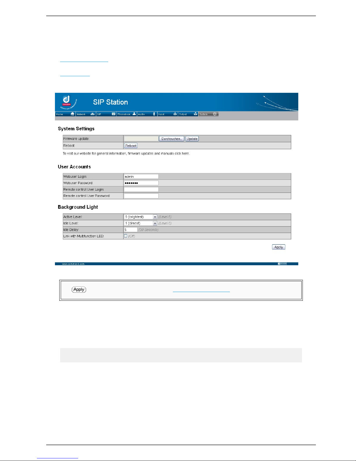
System Settings
Select tab System.
A dropdown menu is opened with following options for selection:
”
System Settings” – Configuration of remote control and the background light, as well as firmware
updates and reboots are carried out.
”
SIP Trace” – Indication of SIP messages.
System Settings
Firmware Update and Reboot
In the section System Settings a firmware update as well as a reboot of the SIP station can be carried
out.
Update of station firmware
In the row Firmware update click on the left button (Browse...)
Select the desired firmware in the dialogue
Click Update to download the selected firmware in the station
All changes in the fields at User Accounts and Background Light are taken over as soon as the button (at the bottom right) is clicked and a ”
Reboot the SIP station” is carried out.
This may take a couple of seconds.
Note:
The description of this button depends on the browser and operating system used.
Page 54
Configuration via Web Interface Commend SIP Series
54 2.0/0612
Reboot the SIP station
To reboot the station, click on the button Reboot.
User Accounts
In the section User Accounts the user settings can be administered:
Webuser Login: Here the user name for the web interface login can be changed.
Webuser Password: Here the password for the web interface login can be changed.
Remote control User Login: Definition of a user name for remote access to the SIP station via
HTTP.
Remote control User Password: Definition of a password for remote access to the SIP station via
HTTP.
Background Light
In the section Background Light the configuration of the backlight for the call buttons and label areas
of the SIP station can be carried out:
Active Level: Configuration of the intensity of the backlight in active mode (e.g. while dialling a call
number) in 10 levels:
Minimum level “1 (dimmest)” to maximum level “9 (brightest)”.
If no modification of the backlight at activity shall take place, then “0 (off)” has to be selected.
Idle Level: Configuration of the intensity of the backlight for idle state of the SIP station in 10 levels:
Minimum level “1 (dimmest)” to maximum level “9 (brightest)”.
If no modification of the backlight in idle state shall take place, then “0 (off)” has to be selected.
Idle Delay: The time (in seconds) of inactivity is defined, after which the backlight illumination is
switched to idle mode (see above).
Link with Multifunction LED: If the checkbox is activated, the behaviour of the backlight illumina-
tion is linked with the LED behaviour (see page 41
). This means, as soon as the LED is on, also the
backlight for the call buttons and label areas is switched on; if the LED is blinking, also the backlight
will be blinking etc. (if e.g. an distinctive optical call indication is required, this function may be the
ideal solution).
Attention:
The dialogue for acknowledgement of the start of the download process is indicated 30 seconds after
the update button has been pressed.
The update button may not be pressed (again) during the active download!
Update from firmware 1.x to 2.0: Settings like e.g. configuration of buttons (”Phonebook Set-
tings” are not saved!
Therefore it is recommended to carry out a Factory Reset after updating to firmware 2.0!
!! ATTENTION !!
During a firmware update the power supply of the SIP station may not be disconnected under
any circumstances – THIS CAN DAMAGE THE STATION!
The firmware update is completed with the reboot of the SIP station.
Note:
How to access the relay outputs by means of a “remote control user account” is described at ”Remote
Control”.
Default: 8
Default: 0 (off)
Default: 30 seconds
Default: deactivated
Page 55
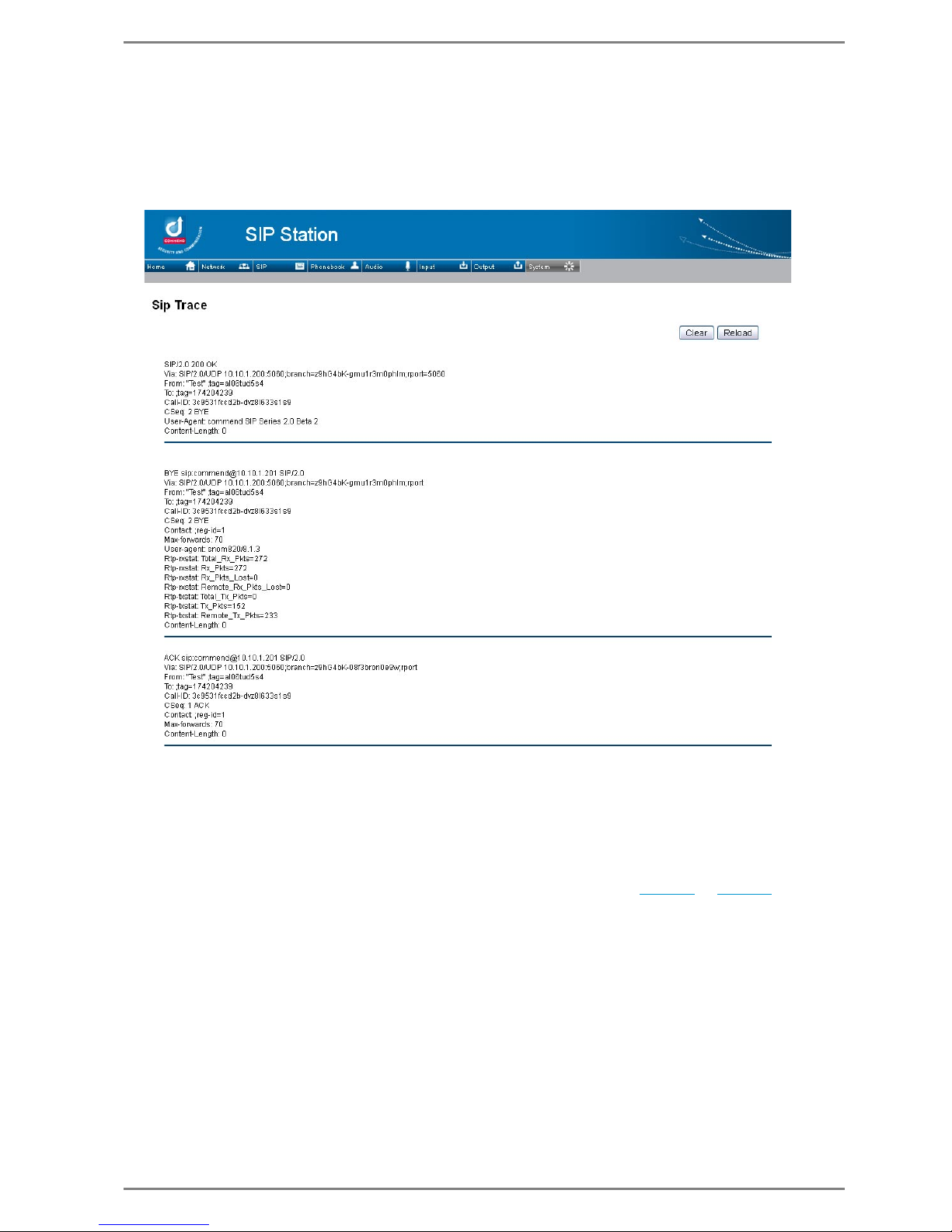
Commend SIP Series Configuration via Web Interface
2.0/0612 55
SIP Trace
If SIP Trace is selected from the drop-down menu, then a list with the current SIP messages are indicated. This makes it easier to reconstruct actions and enables a more effective troubleshooting.
The latest messages are indicated at the top of the list.
Only the last 20 messages will be indicated.
With click on the button Clear all SIP messages are deleted in the list.
With click on the button Reload the list will be updated.
Factory Reset
It is possible to reset all changes made in the web interface settings to factory default:
To reset to factory settings press the “Reset button” on the PCB (see page 29
or page 31) for about
20 seconds during reboot of the SIP station (or at startup after powering on) until the status LED
starts to blink.
Page 56
Configuration via Web Interface Commend SIP Series
56 2.0/0612
Remote Control
To be able to control different operating states for automated processes (or without the authorisation
of a “full access” onto the web interface), the possibility for establishing a “remote control account”
for following actions of the respective station is available:
Switching Relay outputs
Establish Call
Simulation of keypress
Take over / Cancel / Refuse Call
The remote control to the SIP station is enabled by sending HTTP strings.
The HTTP string is made up of 2 parts:
The 1st part of the HTTP string is universally valid and required for all actions to be carried out
<User>: User name for remote access (see “Remote control User Login” on page 54
)
<PW>: Password for remote access (see “Remote control User Password” on page 54
)
<IP address>: IP-Address of SIP station
The 2nd part of the HTTP string is made up of action-specific parameters:
Parameters for Switching Relay Outputs
<1 or 2>: value 1 for relay 1, value 2 for relay 2
<Trigger>: desired trigger mode of relay (see also page 51
):
on: close relay output (activate)
off: open relay output (deactivate)
flashing: switch relay output to blinking
dooropener&dooropenertimer=<time in sec> – door opener function: relay output is closed
for a definable time (“dooropenertimer” e.g. 3 seconds).
toggle: invert current state of the relay output (switch on/off)
Example:
Closing (activating) relay 1 of SIP station 192.168.123.234 (User: Hudson, PW: Saul):
Switching relay 2 of SIP station 192.168.11.22 to blinking (User: Ian, PW: Fraiser):
Closing (activating) relay 1 of SIP station 172.16.9.222 for a (door opener) time of 4 seconds:
Parameter for Simulation Keypress
The remote control account for the “remote control user” is established via the web interface
see ”
User Accounts” on page 54.
http://<User>:<PW>@<IP-Adr.>/cgi-bin/remotecontrol/...
Note:
It is not necessarily required to enter the user name and password in the HTTP string. If the user and
password is not included in the HTTP string, then this data has to be entered after copying (and acknowledging) the string into the browser.
http://<User>:<PW>@<IP-Adr.>/cgi-bin/remotecontrol
/relais.cgi?relais=<1od. 2>&action=<
Trigger
>
http://Hudson:Saul@192.168.123.234/cgi-bin/remotecontrol/relais.cgi?relais=1&action=on
http://Ian:Fraiser@192.168.11.22/cgi-bin/remotecontrol/relais.cgi?relais=2&action=flashing
http://172.16.9.222/cgi-bin/remotecontrol/relais.cgi?relais=1&action=dooropener&dooropenertimer=4
http://<User>:<PW>@<IP-Adr.>/cgi-bin/remotecontrol
/button.cgi?button=<button>
Page 57
Commend SIP Series Configuration via Web Interface
2.0/0612 57
<button>: desired button to be simulated; possible actions:
1-,2,-3-button version: b1 (button 1), b2 (button 2), b3 (button 3)
Stations with full keypad: 1, 2, 3, 4, 5, 6, 7, 8, 9, 0, T, X, menu, up, down, enter
SIP-modules (SIP-ET 908A): 0, T, X
Examples:
Simulation of button 2 of SIP-WS 203V (IP: 192.168.123.234 – User: Hudson, PW: Saul):
Simulation of button 6 of SIP-WS 500F (IP: 192.168.11.22 – User: Ian, PW: Fraiser):
Simulation of Enter button of SIP-WS 800V (IP: 172.16.9.222 – User: SD, PW: Chargers):
Parameter for Take over / Cancel / Refuse Call
<
Call, Conversation
>: desired action at incoming call or active conversation:
take over incoming call: answer
refuse incoming call or cancel active conversation: cancel
Examples:
Take over incoming call at SIP station 192.168.123.234 (User: Hudson, PW: Saul):
Cancel active conversation at SIP station 192.168.11.22 (User: Ian, PW: Fraiser):
Refuse incoming call at SIP station 172.16.9.222 (User: SD, PW: Chargers):
Parameter for Establishing a Call only with full keypad (SIP-WS 800x/500x)
<
Call destination
>: desired call destination; possible settings:
call number only, e.g. 5000
Call Number + Hostname or IP address of the SIP Server, e.g. [email protected]
Examples:
Establish call from station 192.168.123.234 to call destination 5000 (User: Hudson, PW: Saul):
Establish call from station 192.168.11.22 to call destination [email protected] (User: Ian, PW: Fraiser):
Note:
For the different station versions see ”
SIP Series Versions” on page 10.
http://Hudson:Saul@192.168.123.234/cgi-bin/remotecontrol/button.cgi?button=b2
http://Ian:Fraiser@192.168.11.22/cgi-bin/remotecontrol/button.cgi?button=6
http://SD:Chargers@172.16.9.222/cgi-bin/remotecontrol/button.cgi?button=enter
http://<User>:<PW>@<IP-Adr.>/cgi-bin/remotecontrol
/hook.cgi?hook=<Call, Conversation>
http://Hudson:Saul@192.168.123.234/cgi-bin/remotecontrol/hook.cgi?hook=answer
http://Ian:Fraiser@192.168.11.22/cgi-bin/remotecontrol/hook.cgi?hook=cancel
http://SD:Chargers@172.16.9.222/cgi-bin/remotecontrol/hook.cgi?hook=cancel
http://<User>:<PW>@<IP-Adr.>/cgi-bin/remotecontrol
/call.cgi?destination=<Call destination>
Note:
This setting (Call no. without IP address) is not possible for serverless operation!
http://Hudson:Saul@192.168.123.234/cgi-bin/remotecontrol/call.cgi?destination=5000
http://Ian:Fraiser@192.168.11.22/cgi-bin/remotecontrol/call.cgi?destination=[email protected]
Page 58
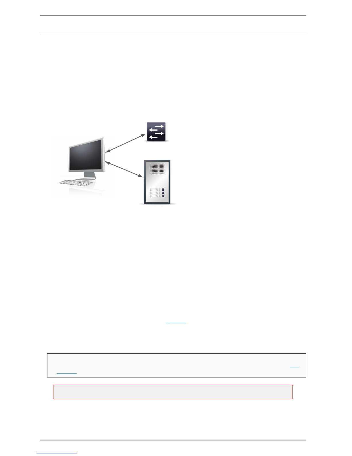
Configuration via Web Interface Commend SIP Series
58 2.0/0612
SNMP
General Definition
The “Simple Network Management Protocol“ (SNMP) is a network protocol for controlling and monitoring network elements (e.g. router, server, switches, SIP stations etc.) via one central management
station/PC. In this process the protocol is controlling the communication between the monitored device and the monitoring station. SNMP describes the structure of the data packets as well as the
communication process.
The state of the respective device is detected by programs (so called “agents”) which are running directly on the monitored device (i.e. SIP station). By means of the SNMP, the “management station” is
able to communicate with this “agent” via network.
Management Information Base
The respective values (of a SIP station) read out by the management station, are described in a
“Management Information Base” (MIB). MIBs are description files in which the single values are listed
in table form. A MIB contain values specifically from one single SIP station only.
Using SNMP Function for SIP Stations
For use of the monitoring function via SNMP for SIP stations, following requirements have to be considered:
SNMPv2c
MIB according RFC 1213
Support for IP-MIB and IF-MIB
Commend-MIB
Private Enterprise Number (PEN): 37568
(for download of the MIB see web link on page 69
)
MIB Browser
By means of a MIB browser the values can be displayed. There are different providers for this type of
browser; some MIB browsers can be downloaded from the WWW as freeware.
In order to be able to use the SNMP function for the SIP station, the feature has to be activated as
well as the IP address of the management station has to be entered via the web interface see
page 37.
Attention:
For reading out the MIB values, the “SNMP Version 2” has to be selected in the MIB browser.
Management station
Reception
Office
Garage
SNMP
e.g. switch
“Agent 1”
“Agent 2”
SIP station
Page 59
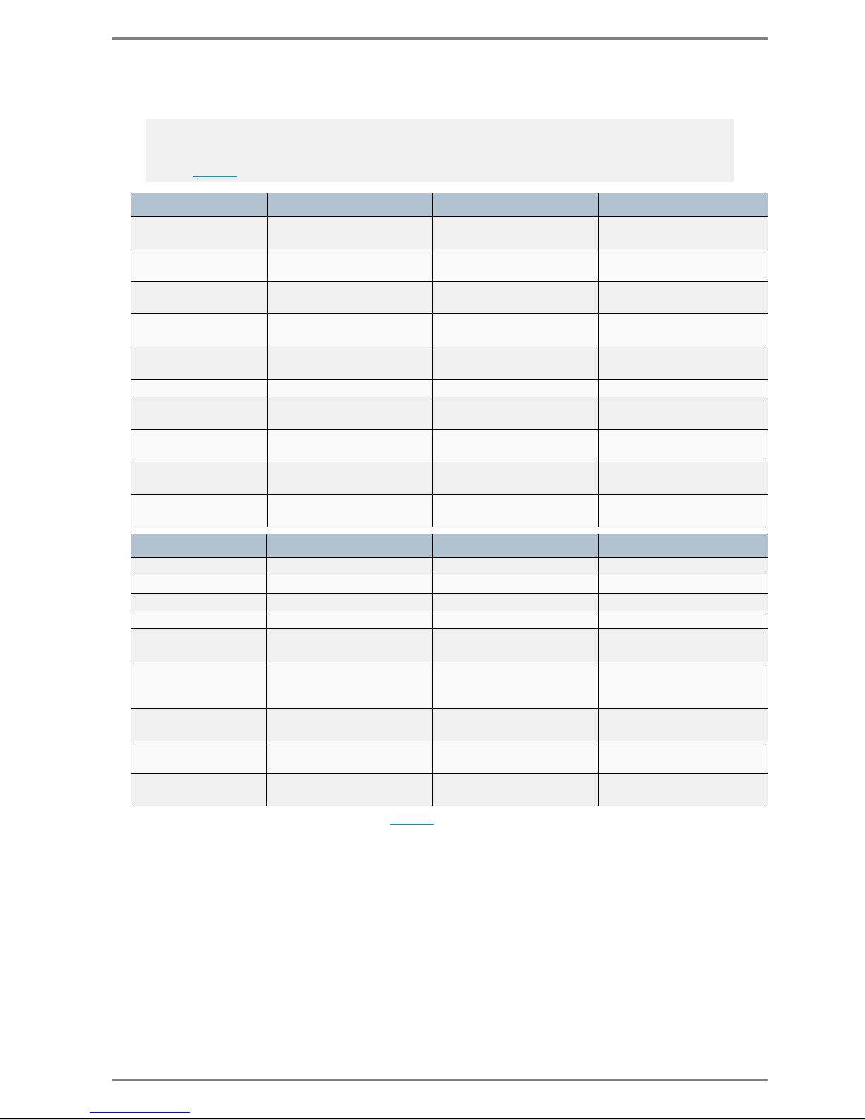
Commend SIP Series Configuration via Web Interface
2.0/0612 59
MIB Values
In the following tables the most essential values for use of SIP stations are listed:
*In case of a change of the state, additionally ”Tr aps” are sent (to the configured host).
Note:
In order that the “Name” of the respective value (2nd column see below) is indicated, the file “commend.txt” (Commend-MIB) has to be read out via the MIB browser (for download of the file see web
link on page 69
).
Device data Name OID Parameter (“Value”)
Station series sysDescr.0 .1.4.6.1.2.1.1.1.0
<Station series>
e.g. Commend SIP Series
Station series
commendStationCommonStationType.0
.1.3.6.1.4.1.37568.2.1.1.1
<Station series>
e.g. Commend SIP Series
Station type sysName.0 .1.3.6.1.2.1.1.5.0
<Station type>
e.g. SIP-ET908A
Station type
commendStationCommonStationSubType.0
.1.3.6.1.4.1.37568.2.1.1.1
<Station type>
e.g. SIP-ET908A
Software version
commendStationCommonStationSoftwareVersion.0
.1.3.6.1.4.1.37568.2.1.1.3 <Software version>
Uptime sys.Uptime.0 .1.3.6.1.2.1.1.3.0 <Uptime of SIP station>
Hardware version
commendStationCommonStationHardwareVersion.0
.1.3.6.1.4.1.37568.2.1.1.4 <Hardware version>
Call number
commendStationCommonStationCallNumber.0
.1.3.6.1.4.1.37568.2.1.1.10 <Call No. of SIP station>
Station description
commendStationCommonStationStationName.0
.1.3.6.1.4.1.37568.2.1.1.11
<Display Name of the SIP
station>
Station location
commendStationCommonStationLocation.0
.1.3.6.1.4.1.37568.2.1.1.12 <Location of the SIP station>
Network data Name OID Parameter (“Value”)
Station IP ipAdEntAddr. .1.3.6.1.2.1.4.20.1.1 <IP Address SIP station>
Station MAC ifPhysAddress.2 .1.3.6.1.2.1.2.2.1.6.2 <MAC address SIP station>
Subnet mask ipAdEntNetMask .1.3.6.1.2.1.4.20.1.3 <Subnet mask>
Router IP ipNettoMediaNetAddress.2 .1.3.6.1.2.1.4.22.1.3.2 <IP Address Gateway>
Online status
commendStationCommonStationOnlineState.0
.1.3.6.1.4.1.37568.2.1.1.20 online, offline
Conversation status*
commendStationCommonStationCallState.0
.1.3.6.1.4.1.37568.2.1.1.80
offhook, onhook, ringing,
dialling, user@domain (conversation partner)
DHCP
commendStationConnectivityType.0
.1.3.6.1.4.1.37568.2.1.2.1 enabled, disabled
Registration status*
commendStationConnectivitySipRegistration.0
.1.3.6.1.4.1.37568.2.1.2.5.1 registered, not registered
Last registration
commendStationConnectivityLastRegistration.0
.1.3.6.1.4.1.37568.2.1.2.5.2
<Time>, > 60 min, never,
unknown
Page 60
Configuration via Web Interface Commend SIP Series
60 2.0/0612
*In case of a change of the state, additionally ”
Traps ” are sent (to the configured host).
Traps
Independently from the values of the MIB, so called “traps” are sent.
A “trap” is an unrequested message of a SIP station to the management station, reporting that an event
has occurred, e.g. a conversation between two SIP stations has been established.
The traps can be displayed by means of a MIB browser
Audio data Name OID Parameter (“Value”)
Microphone type
commendStationAudioMic1Type.0
.1.3.6.1.4.1.37568.2.1.3.1.1
<Microphone type>
e.g. Commend SIP
Microphone
sensitivity
commendStationAudioMic1Sensitivity.0
.1.3.6.1.4.1.37568.2.1.3.1.2 4 – 10
Loudspeaker type
commendStationAudioAmp1Type.0
.1.3.6.1.4.1.37568.2.1.3.10.1
<Loudspeaker type>
e.g. Commend SIP
Speaker volume level
commendStationAudioAmp1Sensitivity.0
.1.3.6.1.4.1.37568.2.1.3.10.2 0 – 12
Echo Suppression
commendStationAudioAECMode.0
.1.3.6.1.4.1.37568.2.1.3.50.1 0 – 4
Noise Suppression
commendStationAudioNCMode.0
.1.3.6.1.4.1.37568.2.1.3.51.1 0 – 4
Relays Name OID Parameter (“Value”)
Description Relay 1
commendStationOutputName1.0
.1.3.6.1.4.1.37568.2.1.5.1.1 Relais 1
Status Relay 1*
commendStationOutputState1.0
.1.3.6.1.4.1.37568.2.1.5.1.2 on, off, flashing
Description Relay 2
commendStationOutputName2.0
.1.3.6.1.4.1.37568.2.1.5.2.1 Relais 2
Status Relay 2*
commendStationOutputState2.0
.1.3.6.1.4.1.37568.2.1.5.2.2 on, off, flashing
Inputs Name OID Parameter („Value“)
Type IN1
commendStationInputType
1.0
.1.3.6.1.4.1.37568.2.1.4.1.1
3 Button Module, 9 Button
Module, Standard
Module, None
Status IN1*
commendStationInputState1.0
.1.3.6.1.4.1.37568.2.1.4.1.2
No Button pressed, Button
<Button> pressed
Type IN2
commendStationInputType
2.0
.1.3.6.1.4.1.37568.2.1.4.2.1
3 Button Module, 9 Button
Module, Standard
Module, None
Status IN2*
commendStationInputState2.0
.1.3.6.1.4.1.37568.2.1.4.2.2
No Button pressed, Button
<Button> pressed
Type IN3
commendStationInputType
3.0
.1.3.6.1.4.1.37568.2.1.4.3.1
3 Button Module, 9 Button
Module, Standard
Module, None
Status IN3*
commendStationInputState3.0
.1.3.6.1.4.1.37568.2.1.4.3.2
No Button pressed, Button
<Button> pressed
Note:
It is possible to define a separate destination IP to where these “traps” are sent, via the web interface
see ”SNMP Settings” on page 38.
Page 61

Commend SIP Series Configuration via Web Interface
2.0/0612 61
For the following events and/or at change of the following states, traps are sent from the SIP station to
the management station:
Registration status (registered, not registered)
Registration data (who is registered at which domain – primary and secondary server)
Conversation status (outgoing/incoming call, idle state, conversation)
Status Call destination (which button is used for which call destination)
Status Ringing (incoming call no.)
Refuse call
Station busy
Status active Conversation (who is talking to whom – from...to)
Status Conversation end (who cancelled the conversation and how has it been cancelled)
Status Relay 1 (on, off, blinking)
Status Relay 2 (on, off, blinking)
Name OID Parameter („Trap“)
commendStationObjectStatus
Notification
.1.3.6.1.4.1.37568.2.10
standby
hung up
dialling
call in
progress
ringing
buttonpressed
remote hung up
<button no.> <user@proxy>,
e.g. button 1, [email protected]
<module no. button no,> <user@proxy>
e.g. module 2 button 7, [email protected]
<short dial no.>, user@proxy
e.g. short dial 5, [email protected]
<arbitrary dialing>
e.g. [email protected]
<http request user>, <user@proxy>
e.g. http request 556, [email protected]
TO: <user> e.g. TO: 556
sip:<user>@<domain>
e.g. sip:[email protected]
.1.3.6.1.4.1.37568.2.1.1
register secondary registration disabled
registered primary, <user>@<domain>
e.g. registered primary, [email protected]
registered secondary, <user>@<domain>
e.g. registered secondary, [email protected]
Page 62
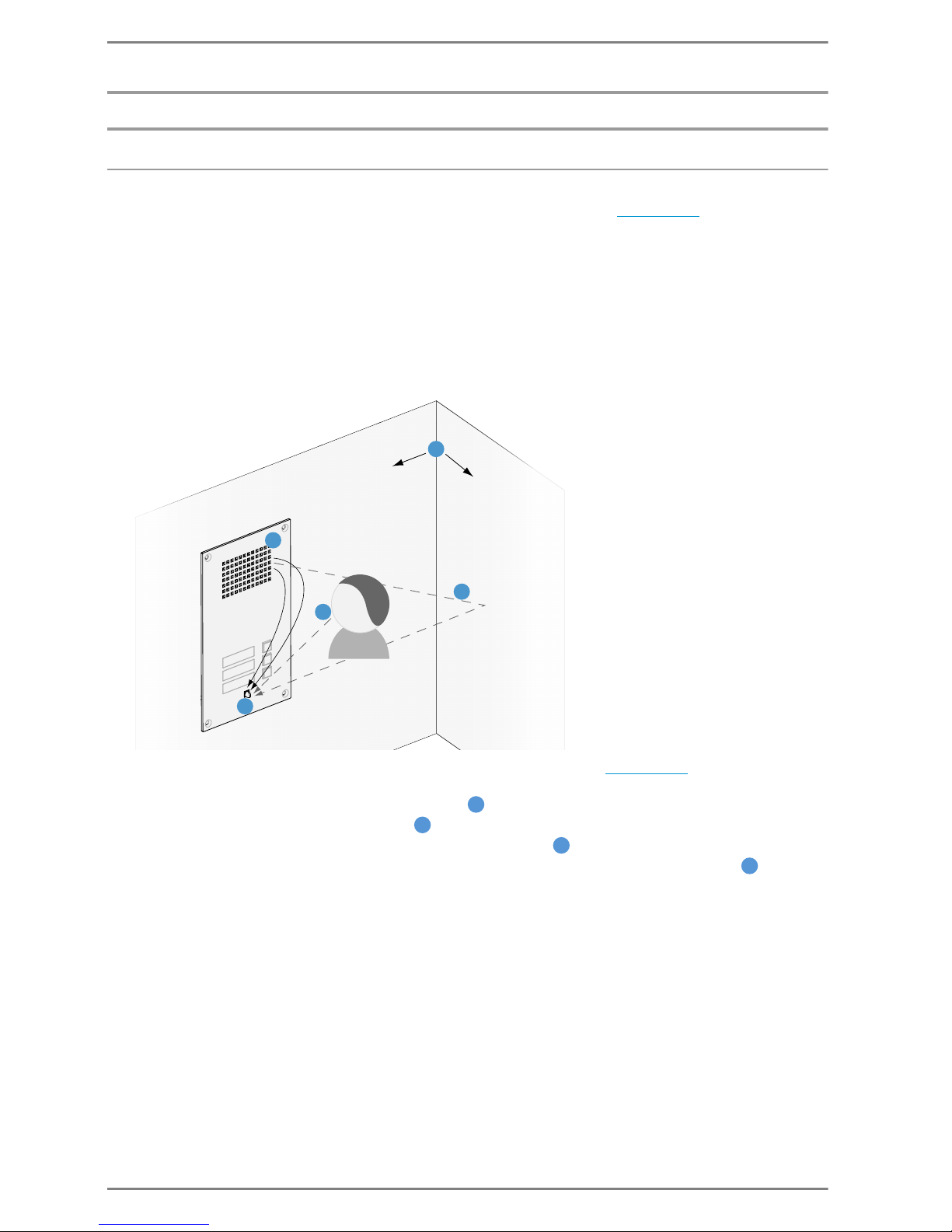
Appendix Commend SIP Series
62 2.0/0612
Appendix
Basic Knowledge about Audio Configuration
In order to carry out a proper audio configuration with the tab Audio (see page 45), basic knowledge
is recommended.
In the following section the various settings and the resulting consequences are explained.
Echo Cancelling according to LS / Mic / Room
“Echo Cancelling” or “Echo Suppression” are methods used to suppress or remove echo or hall effects
at simultaneous sending and receiving of signals (full duplex).
For example, the voice out of the loudspeaker of a hands-free speaking system (e.g. SIP station) during
hands-free speech is picked up by the microphone and transmitted back. Therefore the subscriber on
the other end hears his own voice as an echo.
The following factors determine which “Echo Suppression”-level (see page 45
) is required, to sup-
press Echo on the opposite side:
Configured volume level of the loudspeaker ( )
Configured microphone sensitivity ()
Properties of the Room (size, angles, materials, furnishing )
Distance of the speaker to the station (and therefore the microphone of the station )
Effect of the Configuration always at the other Station/Device
Important information for echo cancelling configuration:
Settings for microphone sensitivity, echo- and noise suppression at the station have direct effects to
the acoustic behaviour at the called station.
Therefore if echo is audible at a device (Intercom, telephone) the configuration needs to be carried
out at the conversation partner!
1
2
3
3
4
1
2
3
4
Page 63
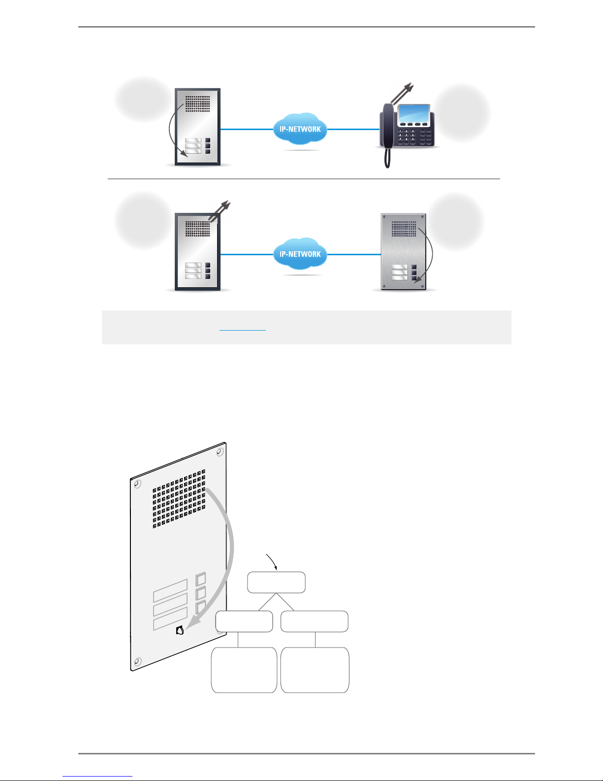
Commend SIP Series Appendix
2.0/0612 63
Possible Consequences of to High Volume
In this section the assumption “louder ≠ better” is described.
If the volume level (“speaker volume”) is increased by several dB, counteractive measures may be
required to ensure a echo-free conversation at the station:
It is possible to decrease the microphone sensitivity (“Mic Sensitivity”) and /or
the Echo Canceller, i.e. the “Echo Suppression”-level is increased
Note:
The standard audio settings (see page 45) are well-proven values and are suitable for a large part of all
applications.
SIP
0
#
*
Reception
Office
Garage
Reception
Office
Garage
Reception
Office
Garage
Configuration
is carried out
at this station
Effects of
configuration
audible at
conversation
partner
Echo audible
at this station
during
conversation
Configuration
has to be
carried out at
conversation
partner
Example 1:
Example 2:
Echo
Echo
Echo
Echo
Counteractive
Measures
Too much Echo
lower
“Mic Sensitivity”
Consequence:
Speaker must
be closer to
microphone or
speak louder
higher
“Echo Suppression”
Consequence:
The conversation
might feel more
like with switched
duplex/half duplex
Page 64
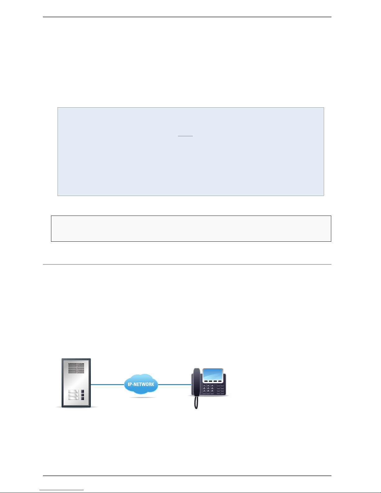
Appendix Commend SIP Series
64 2.0/0612
Microphone sensitivity is reduced – consequence:
In order for the called station to hear the speaker properly, the distance to the microphone must be
decreased or the speaker must speak louder.
Echo Suppression is increased – consequence:
The more the “Echo Suppression”-level is increased, the more the conversation feels as if switched
with a “speech balance” (like switched duplex/ half duplex).
This “speech balance” takes control of the conversation direction and switches through the louder
side of the conversation and reduces the volume of the quieter side.
Unique Feature of the SIP Series
Serverless Operation
The following section gives an overview of the required basic configuration of a SIP station as well as
a SIP telephone, at serverless operation.
As example a Snom®telephone is used.
A detailed description of the Snom®web interface won´t be found in this document, as on the basis of
the following example solely the basic know-how for the configuration of a serverless operation between two SIP devices, shall be communicated.
Connection Commend SIP Station – Snom®Phone
WHAT IS A SPEECH BALANCE?
A “speech balance” is used in a “half duplex” conversation.
Because the stations of the SIP Series are “full duplex” capable, the speech balance is not active (ex-
works). Only when a special configuration (see above) is carried out, the conversation is controlled by a
similar behaviour.
For a clearer understanding please read the description of the two conversation modes:
HALF DUPLEX (SPEECH BALANCED):
The conversation direction is controlled by a “speech balance”. Therefore it is possible to talk and listen
without pressing a button. However only the louder side is switched through.
FULL DUPLEX:
The conversation is permanently switched through in both directions. Therefore both conversation partners can simultaneously speak and listen (=natural communication).
The great advantage of the SIP Series compared to other products is, that the above-mentioned
behaviour can be adapted to the requirements on site and therefore provide the greatest possible
conversation quality.
Snom
®
0
#
*
Reception
Office
Garage
IP: 10.10.1.201
IP: 10.10.1.200
Dummy Account: 124
Page 65
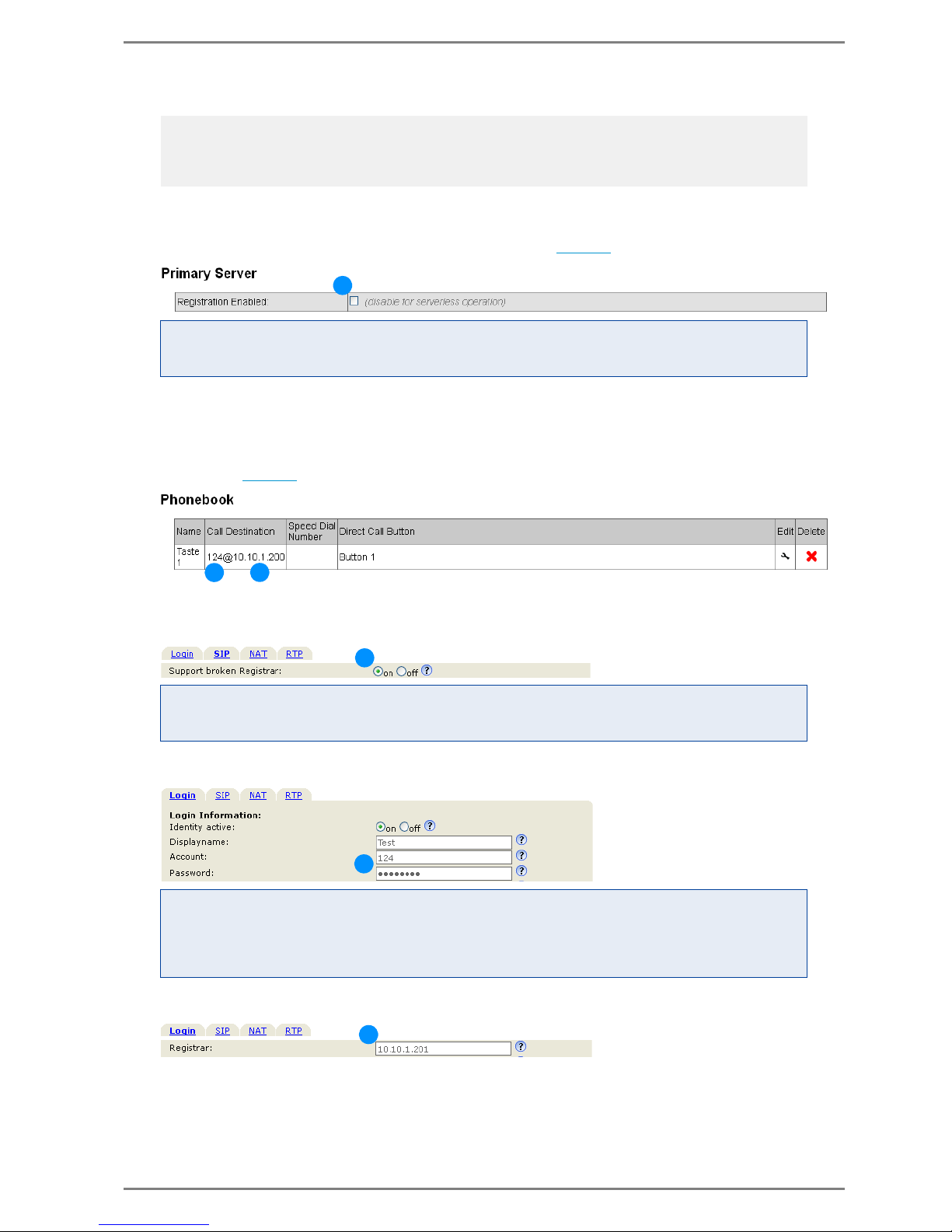
Commend SIP Series Appendix
2.0/0612 65
Required Configuration of the SIP Station
Deactivate checkbox “Registration Enabled” (see also page 40).
Configuration of the appropriate Call destination (Snom®telephone), i.e.:
the call number (“dummy account”) of the Snom®telephone
the IP address of the Snom®telephone
desired direct dialling number or direct dialling button
(see also page 42
).
Required Configuration for Snom®Phone
Activate “Support broken Registrar” to enable an operation without server.
Create Dummy-Account (e.g. “124” + Password).
At “Registrar” the IP address of the conversation partner, i.e. of the SIP station is entered.
Note:
The following Snom®web interface description relates to version 8.
The indicators “a1”, “b1”, “c1” in the screenshots of the web interface of the SIP station correlate
with the settings “a2”,“b2”,“c2” in the web interface of the Snom®telephone.
WHY THIS SETTING?
The deactivation of the checkbox enables a serverless connection between 2 SIP devices. I.e. there will
be no attempt of the SIP station to register at a SIP server.
WHY THIS SETTING?
The activation of the option field “on” enables a serverless connection of the Snom®telephone to a SIP
terminal (e.g. Commend SIP station).
WHY THIS SETTING?
As no server is in use, no SIP account for the registration on a server can be created. In order a connection between the SIP station and Snom®Phone can be established (i.e. the Snom®Phone can be addressed correctly), a so called “dummy” account (call no. and password) for the Snom®Phone via web
interface is required.
a1
b1
c1
a2
b2
c2
Page 66
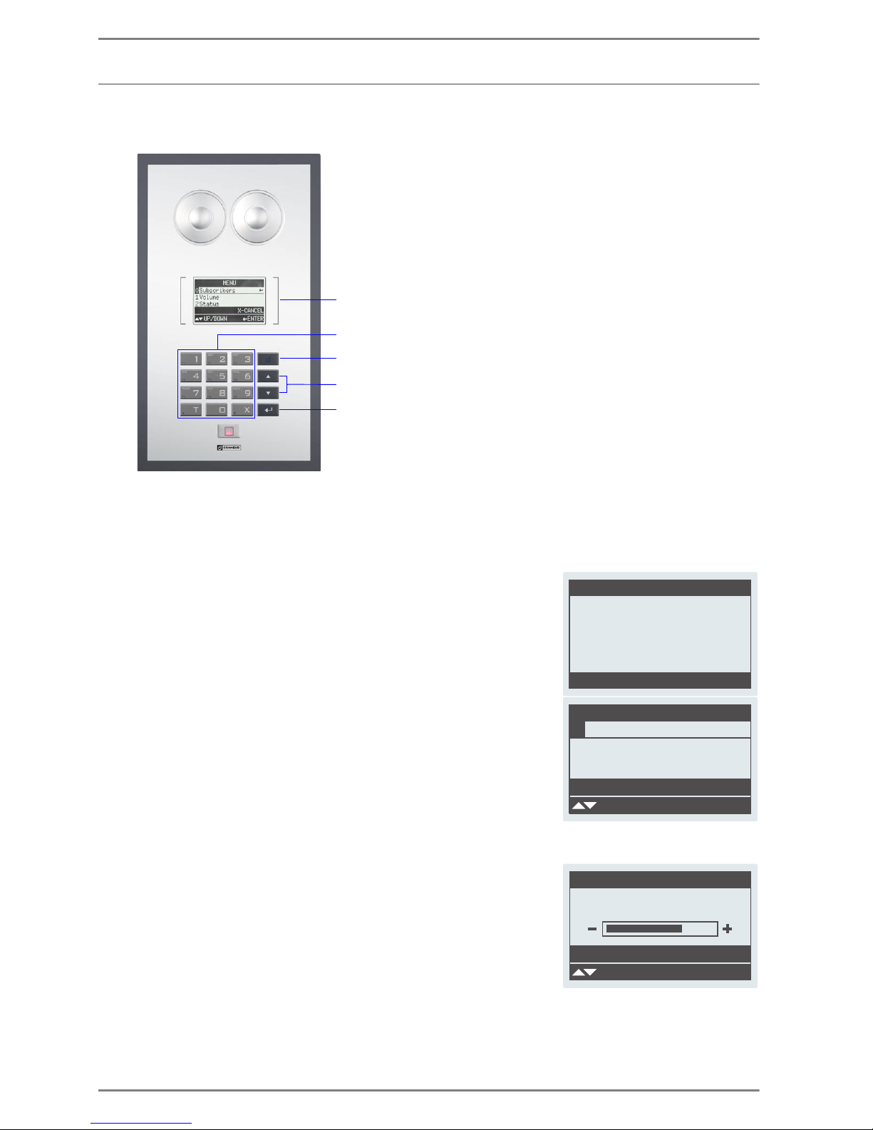
Appendix Commend SIP Series
66 2.0/0612
Display Menu WS 800V / WS 800F
Following sections provide display menu operating instructions for the SIP stations WS 800V and
WS 800F.
Help Functions
Possible inputs are indicated at the bottom of the display as help.
Idle Mode
In idle mode, the screen to the right is indicated.
Main Menu
Open the menu in idle mode with menu button .
With the arrow buttons an option is selected and initiated with
.
With
the Main Menu can be left without selecting an option.
Subscriber: Show the subscriber list
Volume: Show menu “Volume”
Status: Show information about the station (call no., name, versions)
Volume
Select Volume from the main menu with .
With the arrow buttons the desired volume is selected.
Save with
or leave with without saving any changes.
Alpha numeric full keypad
Menu button
Arrow buttons Up / Down
Enter button
LCD graphic display
STANDBY
MENU
Status2
Volume1
Subscriber0
MENU
UP/DOWN ›OK
X-CANCEL
›
VOLUME
+/-
›SAVE
X-CANCEL
Page 67
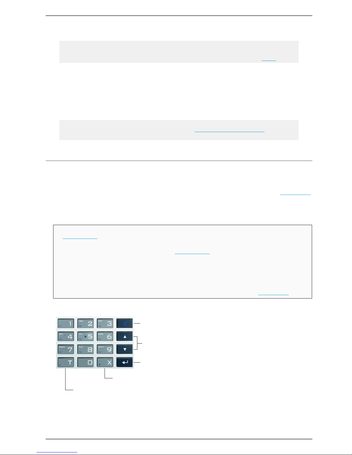
Commend SIP Series Appendix
2.0/0612 67
Status
Here the station data is indicated, like e.g. IP address, registration status, version.
Select Status from the main menu with
.
Leave the menu with
.
Call Initiation at SIP-WS 500F
As the SIP-WS 500F do not contain any display, the operation is facilitated with the output of audio signals.
The way a call is initiated depends on whether the checkbox Allow Arbitrary Dailing (see page 41
)
is activated or deactivated:
Allow Arbitrary Dailing NOT activated
Buttons
Note:
The volume can also be controlled during an active conversation.
With the respective volume is saved also for the next conversation (as described above).
General Note:
According to the selected option at Answer Call (tab SIP see ”
Call Settings” on page 40) different dis-
play screens at incoming calls are possible.
After a button is pressed, it is checked whether the dialled call number is stored in the
”
Phonebook”.
If a match is found, then the call number will be dialled immediately.
If the call number could not be found in the ”
Phonebook”,
then the complete number is deleted after a timeout of 10 seconds and
a double tone is put out and the “input mode” is restarted, i.e. a new number can be
dialled.
If the complete “line” or last digit is deleted, then
a double tone is put out and input mode is restarted, i.e. a new number can be dialled
The conversation can be cancelled according to the respective configuration see page 40
.
Menu button: no function
Volume controllable by arrow buttons
Enter button: only saving volume
press short: delete last digit
press for at least 1 second: delete complete line (call number)
no function
Page 68
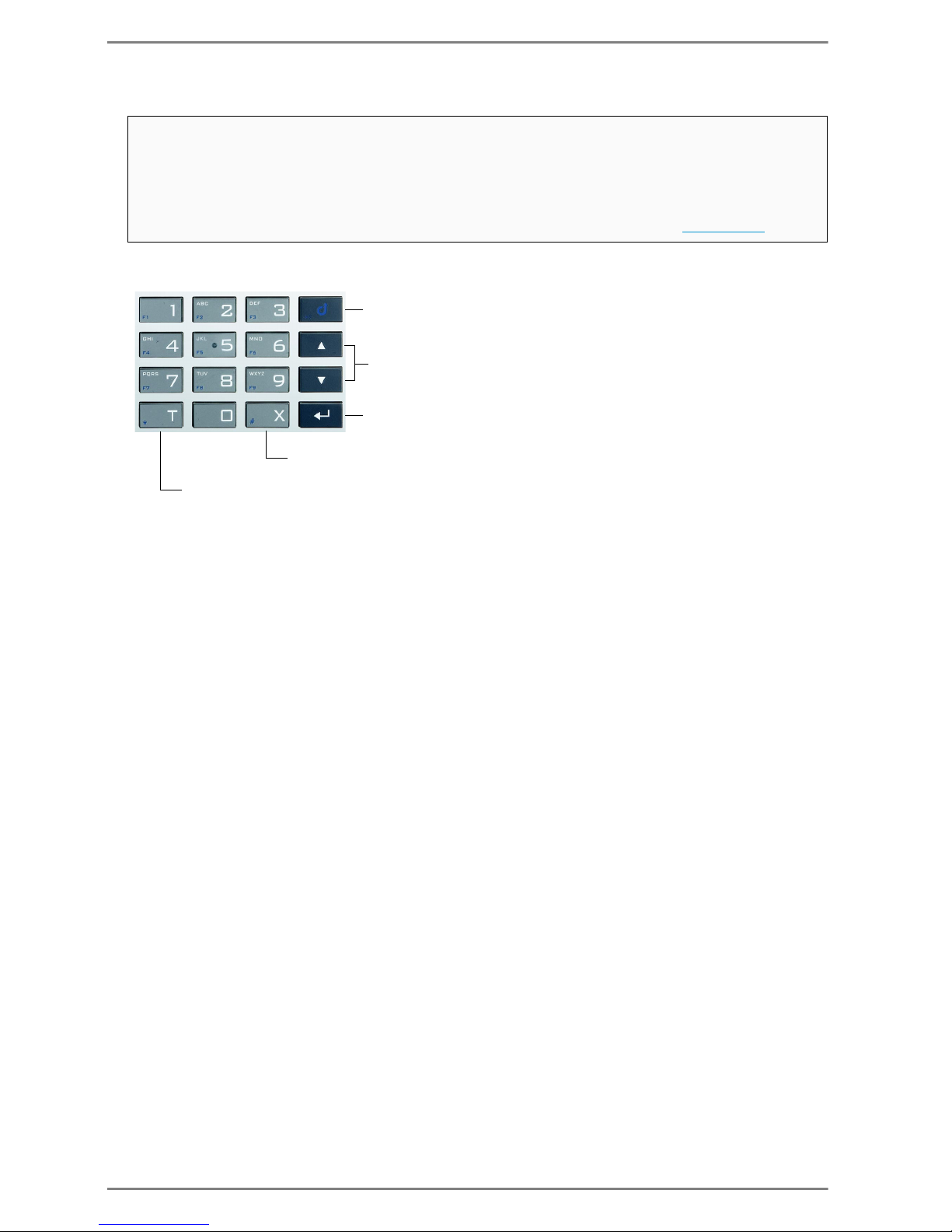
Appendix Commend SIP Series
68 2.0/0612
Allow Arbitrary Dailing activated
Buttons
After a the Enter button is pressed, the entered call number is dialled.
If no button is pressed within a timeout of 10 seconds, then
a double tone is put out and input mode is restarted, i.e. a new number can be dialled
If the complete “line” is deleted, then
a double tone is put out and input mode is restarted, i.e. a new number can be dialled
The conversation can be cancelled according to the respective configuration see page 40
.
Menu button: no function
Volume controllable by arrow buttons
Enter button: saving volume, setting up the call
press short: delete last digit
press for at least 1 second: delete complete line (call number)
no function
Page 69

Commend SIP Series Technical Support
2.0/0612 69
Technical Support
For more information about the Commend SIP Series visit:
www.commend.com/sip
 Loading...