

Page 1

P4VMA User’s Manual
P4VMA
Motherboard
Users Manual
Product Name: P4VMA
Manual Revision: English, 1.0
1
Page 2

P4VMA User’s Manual
Trademarks
Intel, Socket 478,Northwood 478-pin mPGA CPU are trademarks of Intel Corporation
S3 VIA is a registered trademark of VIA Technologies, Incorporated.
Award is a trademark of Award Software International Inc.
MS-DOS, Windows 95, Windows 98, Windows ME, Windows XP, Windows 2000 and
Windows NT are registered trademarks of Microsoft Corporation
Novell is a trademark of Novell Corporation
C-Media is a trademark of C-Media Technology
All other brand and product names are trademarks or registered trademarks of their respective
companies.
2
Page 3

P4VMA User’s Manual
Table of Contents
Chapter 1. Introduction
1.1 Product Overview.….……………………………………………………..……..… ...5.
1.2 Features.………………………………………………………………………..……..6
1.3 Specifications.…………………………………………………………………..…….6
1.4 Content……….…………………………………………………………………..……9
1.5 System Board Layout….……………………………………………………..………9
Chapter 2. Hardware Setup
2.1 Installation Procedure..………………………………………………………….… …10
2.1.1 Jumper Settings..…….……………………………………………………….…10
2.1.2 Clearing the CMOS..……………………………………………………………10
2.2 Installation of CPU..……………………………………………………………………11
2.2.1 For Socket 478 CPU.……………………………………………………………11
2.3 Installation of Memory...……………………………………………………………….11
2.3.1 Installation of 184-pin DIMM.……………………………………………………11
2.3.2 Removal of 184-pin DIMM...…………………………………………………….11
2.3.3 Memory Configuration……………………………………………………………12
2.4 I/O Connections/Panel Connections………………………………………………….13
2.4.1 ATX Power Connector…………………………………………………….………13
2.4.2 Chassis and CPU Fan Connector…………………………………….…….… ...14
2.4.3 Infrared Connector…………………………………………………………….… ..14
2.4.4 Wake-up On LAN or Modem……………………………………………….… ....15
2.4.5 Floppy Disk Drive Connector………………………………………………… .....15
2.4.6 Primary/Secondary IDE Connector.……………………………………………..16
2.4.7 PS/2 Mouse Port.………………………………………………………………….16
2.4.8 PS/2 Keyboard Connector.……………………………………………………….16
2.4.9 VGA Connector…………………………………………………………………….16
2.4.10 Serial Port.………………………………………………………………………..16
2.4.11 Printer Port.…………………………………………………………………....… .16
2.4.12 USB Connectors……………..……….…………………………………….……..17
2.4.13 LAN Connector……………………………………………………………………17
2.4.14 ACT/LINK LED…………………………………………………………………….17
2.4.15 Speed LED…………………………………………………………………………17
3
Page 4

P4VMA User’s Manual
2.4.16 Game/MIDI Port… .………………………………………………………………17
2.4.17 Center/Bass phone jack……………..……… ……………………………..…17
2.4.18 Front phone jack……………..……………………………………………….….17
2.4.19 Rear phone jack...…………………………………………………………………18
2.4.20 CD_IN Audio Connec tor………………………………………………………….18
2.4.21 Panel Connection…………………………….……………………………………18
2.4.22 Audio extra function connector setting…….……………………………………19
Chapter 3. BIOS Setup
3.1 CMOS Setup Utility.………………………………………………..………………………19
3.2 Standard CMOS Setup…………………………………………………………………….20
3.3 Advanced BIOS Features Setup………………………………………………………….22
3.4 Advanced Chipset Features Setup……………………………………………………….25
3.5 Integrated Peripherals.…………………………………………………………………..… 32
3.6 Power Management Setup.……………………………………………………………..…36
3.7 PNP/PCI Configuration Setup……………………………………………………….….… 41
3.8 PC Health Status……………………………………………………………………………44
3.9 Frequency/Voltage Control………………………………………………………...………45
3.10 Load Fail-Safe Defaults……………………………………………………………….…..46
3.11 Load Optimized Defaults… ………………………………………………………….……47
3.12 Set Supervisor/User Password…………………………………………………………..47
3.13 Save & Exit Setup.…………………………………………………………………………47
3.14 Exit Without Saving.…………………………………………………………………….….47
Chapter 4. Software Installation
4.1 Install Motherboard Software…………………………………………………….…………48
4.2 Install Ultra ATA……………………………………………………………………….…..…48
4.3 Install Audio Device Software………………………………………………………………48
4.4 Link to < Website > Homepage…………………………………………………………….48
4.5 Browse this CD……………………………………………………………………………….48
Appendix A Using the Suspend to RAM Function………………..49
4
Page 5

P4VMA User’s Manual
Chapter 1. Introduction
1.1 Product Overview
Thanks for your purchasing the P4VMA motherboard. The new ATX,
478-pin mPGA Motherboard P4VMA supports a full range of the latest
generation Intel Pentium 4 processors.The leading edge chipset S3 VIA
P4M266 & VT8233 was designed for working with Pentium 4
(1.4GHz-2.0+GHz) and Northwood processor (min. 2.0GHz) in the
478-pin package based on the VRM 9.0 Spec. And up at 400 MHz system
Data Bus. Built using the leading edge technology the Intel Pentium 4
processors provide a significant performance over previous Pentium III
processors.
Four PC1600/2100 (DDR200/266) sockets allow for up to 2.0GB memory
capacity. We have conducted a motherboard compatibility test with a
variety of hardware and software, such as CPUs, memory, display cards,
CD ROMs, Novell, MS Office.... etc.
We have set high standards on our quality control, with absolute
confidence; we believe this product is the wisest choice.
This manual is composed of four sections. The first section is the
introduction of this motherboard, and the second section explains the
proper procedure to setup the motherboard, the third section provides
information on how to setup the CMOS. The last sec tion is the installation
of the device drivers & utilities.
Ordering Codes
P4VMA: Uses VIA S3 P4M266 and VIA VT8233 chipset with LAN.
5
Page 6

P4VMA User’s Manual
1.2 Features
• Wake up on LAN.
• Modem Remote Ring On.
• Support NCR SCSI BIOS.
• Support Ultra DMA 66/100.
• Support Hardware Monitor function.
• C-Media CMI 8738MX with 6 channels speaker out on board.
• Support 400MHz FSB frequency.
• Allows CPU settings and easy over clocking of frequency.
• Support Advanced Configuration Power Interface (ACPI).
• Support Desktop Management Interface (DMI) through BIOS.
• Low-power sleep modes, and 2Mbits “Plug & Play ” Flash ROM.
• RTC Wake up Alarm: Program the date/time to wake up your
system.
• Support AGP 2.0 slot for external AGP 2X/4X Fast Write
protocol graphics card upgrade.
• Both the BIOS and hardware levels of the motherboard meet PC
'99 compliant.
1.3 Specifications
CPU :
• P4VMA support Intel Socket 478 mPGA Pentium 4 Northwood
CPU with 400MHz FSB frequency.
Chipset:
• S3 VIA P4M266 (build-in S3 Graphics ProSavage8 core on chip)
and VIA VT8233
DIMM:
• Supports 2.5V PC1600/2100 (DDR200/266)-compliant DDR
DRAM in two 184-pin sockets, which can support
64,128,256,512MB and 1GB DDR DIMM modules.
• Supports 4-banks up to 2GB DRAM for unbuffered DDR DRAM
module.
• Optional bank -by-bank ECC (single-bit error correction for
DRAM integrity).
6
Page 7

P4VMA User’s Manual
VGA: . S3 Graphics ProSavage8 integrated graphics core on chip.
. Support V-Map share system max. 32 MB of frame buffer
capability.
. Enhanced 128bit 3D/2D engines and DVD,DXVA motion
compensation.
IDE:
• Dual channel PIO and PCI Bus Master IDE ports support up to 4
EIDE devices for HDD, CD-ROM or DVD-ROM.
• Supports PIO Mode 4 with data transfer rate up to 14 MB/Sec
• Supports Multiword DMA Mode 0, 1, 2.
• Support Ultra DMA ATA -100 can enhance 30% performance.
Expansion Slots:
• Three 32-bit PCI expansion slots (Rev. 2.2)
• One 32-bit AGP expansion slot (Rev. 2.0)
BIOS :
• Award BIOS v6.00PG with built-in Anti-Virus, DMI, ACPI
support, and green function (Plug-and-Play BIOS)
• Supports CD-ROM/HD/SCSI/Floppy/LS120/ZIP and LAN boot
up.
• Supports NCR SCSI BIOS.
USB Ports :
• Six Universal Serial Bus (USB) ports Rev.1.1, support up to
127 peripheral devices.
Sound :
• C-Media CMI 8738/PCI-6CH-MX 4/6 channels sound chipset.
• HRTF–base 3D positional audio (C3DX) for 4/6 CH output.
• Professional digital interface, supporting 24-bit SPDIF IN/OUT
(44.1K and 48K).
• Built-in 32ohm earphone buffer, ZV port, and Pctel HSP56
Modem interface.
• 32-bit PCI bus master.
• Comprehensive driver support: Microsoft DirectSound 3D, EAX,
Linux, BeOS, etc.
• Microphone echo and Karaoke ascending/descending key
effects.
• Single chip design, digital power +3.3V, analog power +5V.
7
Page 8

P4VMA User’s Manual
LAN:
. High performance PCI master interface with scatter/ gather and
bursting capability.
. 10/100Mbps full or half duplex operation.
. Separate 2K byte FIFOs for receive and transmit.
. Enabled software control power down.
I/O Devices :
• One FDD control port supports two of the 5.25" or 3.5" floppy
drives up to 2.88 MB.
• Two high-speed 16550 UART compatible serial ports
• One parallel ports with SDP/ECP/ EPP compatibility.
• One PS/2 mouse port
• One PS/2 Keyboard connector
IR Port :
ATX Power :
Operating System :
Dimension :
1.4 Content
The motherboard box contains the following items:
• One IrDA/ASKIR compatible Infrared interface port. (Cable
optional)
• Supports Modem remote Ring-On function
• Supports software power off function
• Supports RTC Wake-Up.
• Supports Wake up on LAN.
• Supports Keyboard Wake-Up.
• Supports Windows 3.x/95/98/ME/2000/XP, Windows NT,
MS-DOS V6.22, OS/2, Novell, Unix, SCO UNIX.....
• 245 mm x 220 mm Micro-ATX Form factor
• One Motherboard
• One 80-pin IDE Ribbon Cable
• One Floppy Ribbon Cable
• One 9pins D-sub Cable
• One Driver CD
• User's Manual
8
Page 9
P4VMA User’s Manual
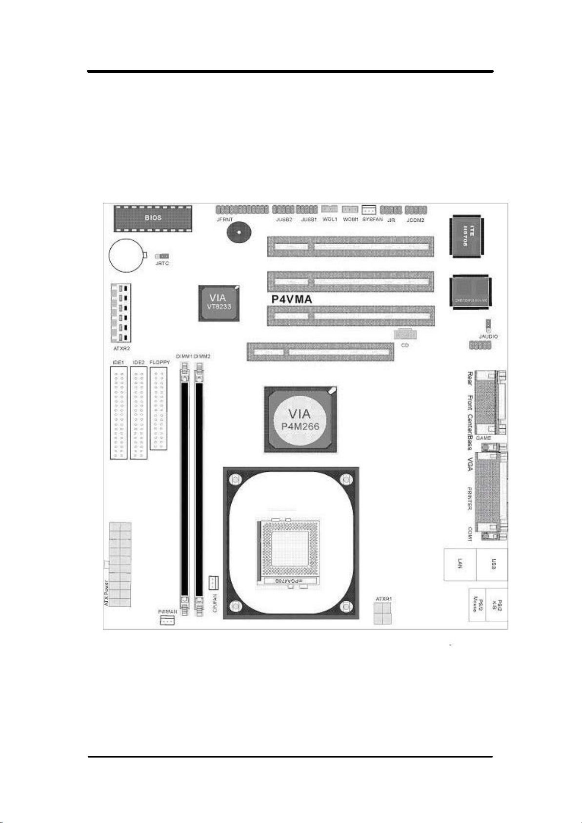
1.5 MotherBoard Layout
9
Page 10
P4VMA User’s Manual
Chapter 2. Hardware Setup
2.1 Installation Procedure
1. Jumper settings
2. Installation of CPU
3. Installation of Memory
4. I/O Connections & Panel Connections
2.1.1 Jumper Settings
In this manual, (1-2) represents the first and second pins of the
jumper. (2-3) Represents the second and third pins of the jumper.
On the motherboard, you will see two sets of jumpers with different
color jumper caps:
Yellow Jumper Caps: Sets the Function of Flash CMOS JRTC
WARNING:
• Electronic parts are Static sensitive. To prevent damage to
the computer and its parts please take the following measures.
• Work on a surface such as concrete, linoleum or hard
wood floor.
• Ground your self with either a properly installed grounding
strap or by touching a major electrical appliance long enough
to discharge the static.
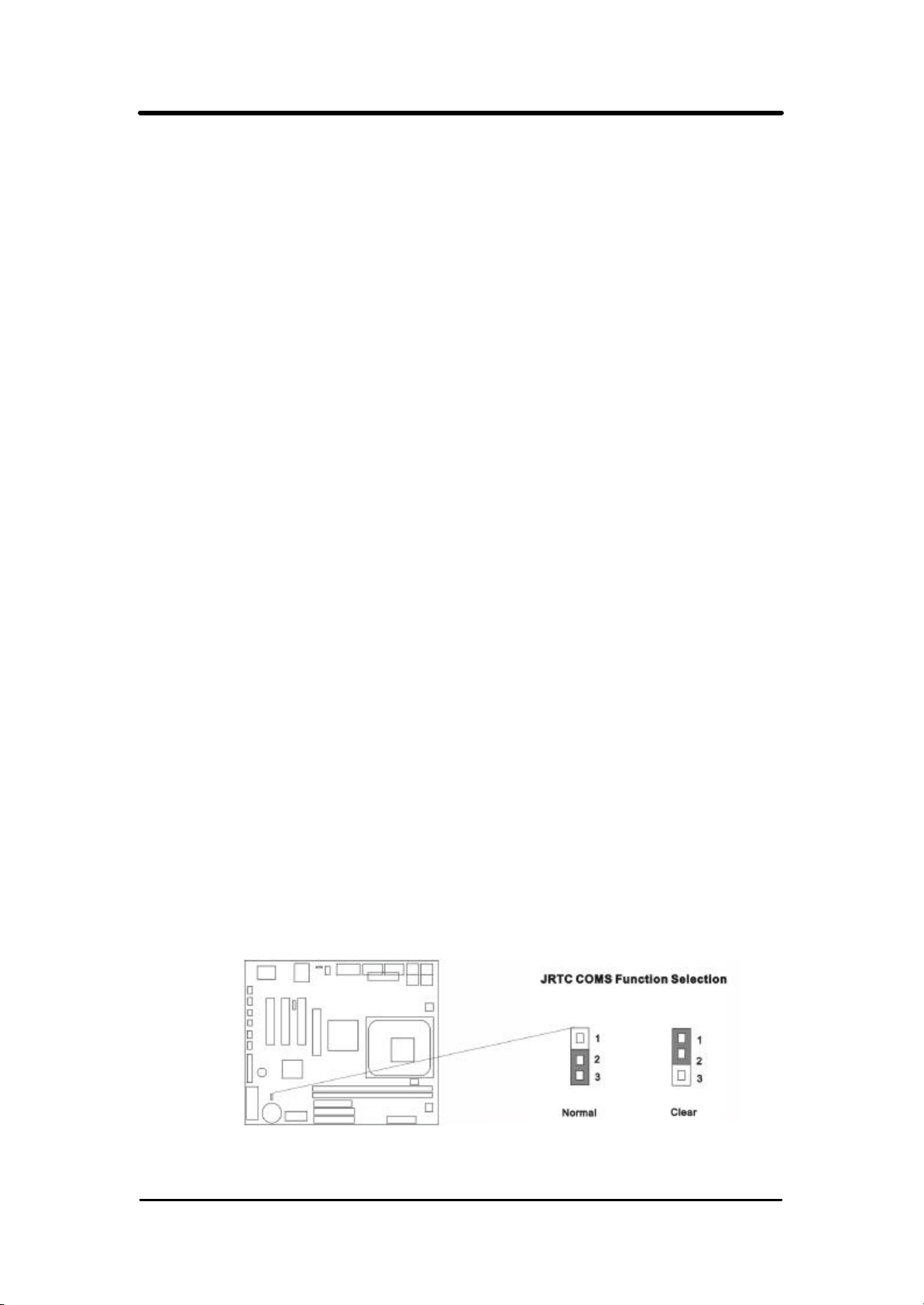
2.1.2 Clearing the CMOS (Yellow Jumper Cap)
JRTC: CMOS Function Selection
1-2:Clear data
2-3:Normal Operation (Default Setting)
10
Page 11

P4VMA User’s Manual
How to Clear the CMOS Setting
1. Turn off the power.
2. Remove ATX power cable from connector J1.
3. Remove Yellow Jumper Cap from JRTC (2-3) and put on
JRTC (1-2) to remove the CMOS setting.
4. Remove Yellow Jumper Cap from JRTC (1-2) and put on
5. JRTC (2-3).
6. Connect ATX power cable back to connector J1.
7. Turn on the power.
8. While the system reboots, press <DEL> key to set the
BIOS setup.
2.2 Installation of CPU
2.2.1 For Socket 478 CPU
Before installing CPU, make sure the power is off. Locate the level bar
on the mPGA478 ZIF socket. Push level bar away from the socket and
pull upward 90 degrees. Insert the CPU into the socket. Be careful of
CPU orientation. Make sure the notch of the CPU corresponds with the
white dot on the ZIF socket (the corner without pin socket). Do not push
in the CPU. Make sure all pins are aligned with the CPU socket. on the
level bar.
2.3 Installation of Memory
This motherboard has 4x184-pin 64 -bit Dual Inline Memory Module (DIMM)
sockets divided into 8 banks. You can install 2.5V Unbuffered
PC1600/2100-compliant Synchronous DRAM (DDR RAM) memory.
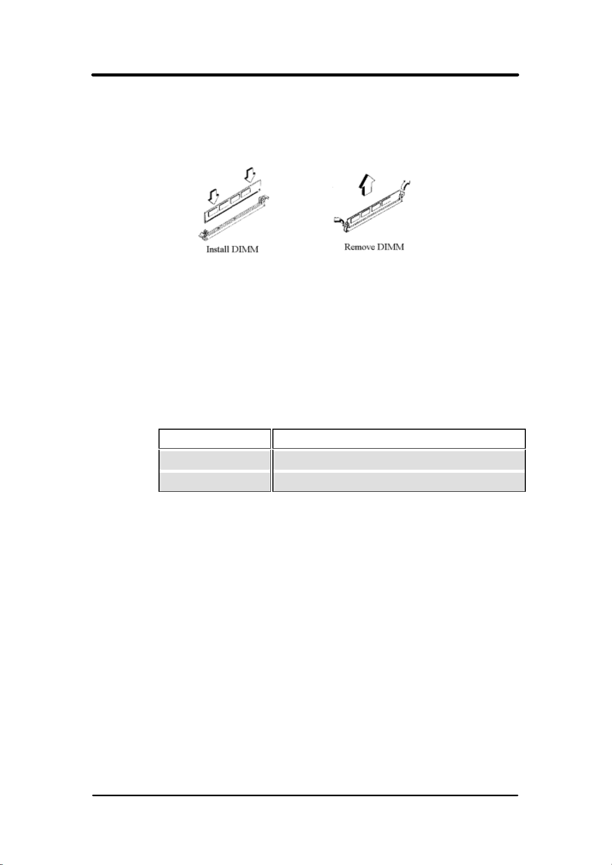
2.3.1 Installation of 184-pin DIMM (Dual Inline Memory Module)
1. Before inserting the DIMM, make sure the pin1 of the
DIMM matches with the pin1 on the DIMM socket.
2. Insert DIMM into the DIMM sockets at a 90-degree angle
and press down.
11
Page 12
P4VMA User’s Manual
2.3.2 Removal of 184-pin DIMM
1. Press the holding clips on both sides of the socket outward
to release the DIMM.
2. Gently pull the DIMM out of the socket.
2.3.3 Memory Configuration
There is no jumper setting required for the memory size or type. It is
automatically detected by the system BIOS, and the total memory size
is to add them together
Supports 4-banks up to 2 GB DRAM for register DDR SDRAM
unbuffered DDR SDRAM module.
DIMM Socket DIMM Modules
DIMM1 PC1600/2100 DDR SDRAM 64, 128, 256, 512MB,1GB
DIMM2 PC1600/2100 DDR SDRAM 64, 128, 256, 512MB,1GB
12
Page 13
P4VMA User’s Manual
2.4 I/O Connections/Panel Connections
I/O Connections
CN 7,J11,J10 ATX Power series Connector
CPU/PWA/SYS FAN CPU/PWA Fan connector
JIR1 Infrared Connector (Cable optional)
WOL1, WOM1 Wake up on LAN /Modem connector
FLOPPY Floppy Disk Drive Connector
IDE1, 2 Primary/ Secondary IDE Connectors
MS1 PS/2 Mouse Port
KB PS/2 Keyboard Connector
LAN 10/100Mbps Ethernet Connector
COM1 Serial Port 1
JCOM2 Jumper for adding Serial Port 2
VGA VGA Connector
PRINTER Printer Port
CN2, JUSB 1/2 USB, USB1, 2 Connector
GAME Game/MIDI Connectors
Center/Bass Center/Bass phone jack
Front Front phone jack
Rear Rear phone jack
CD_IN The Connector is for CD_IN audio cable
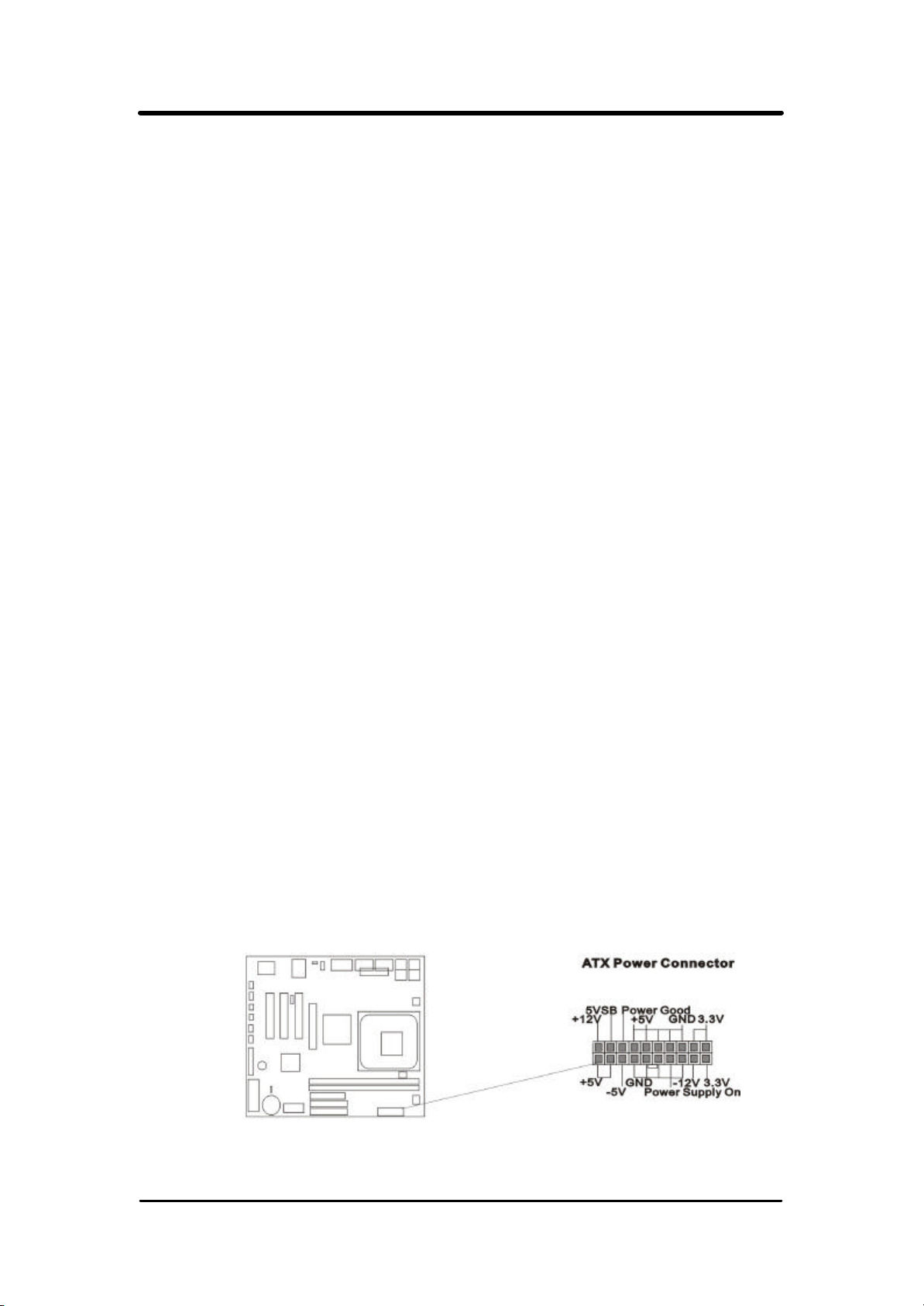
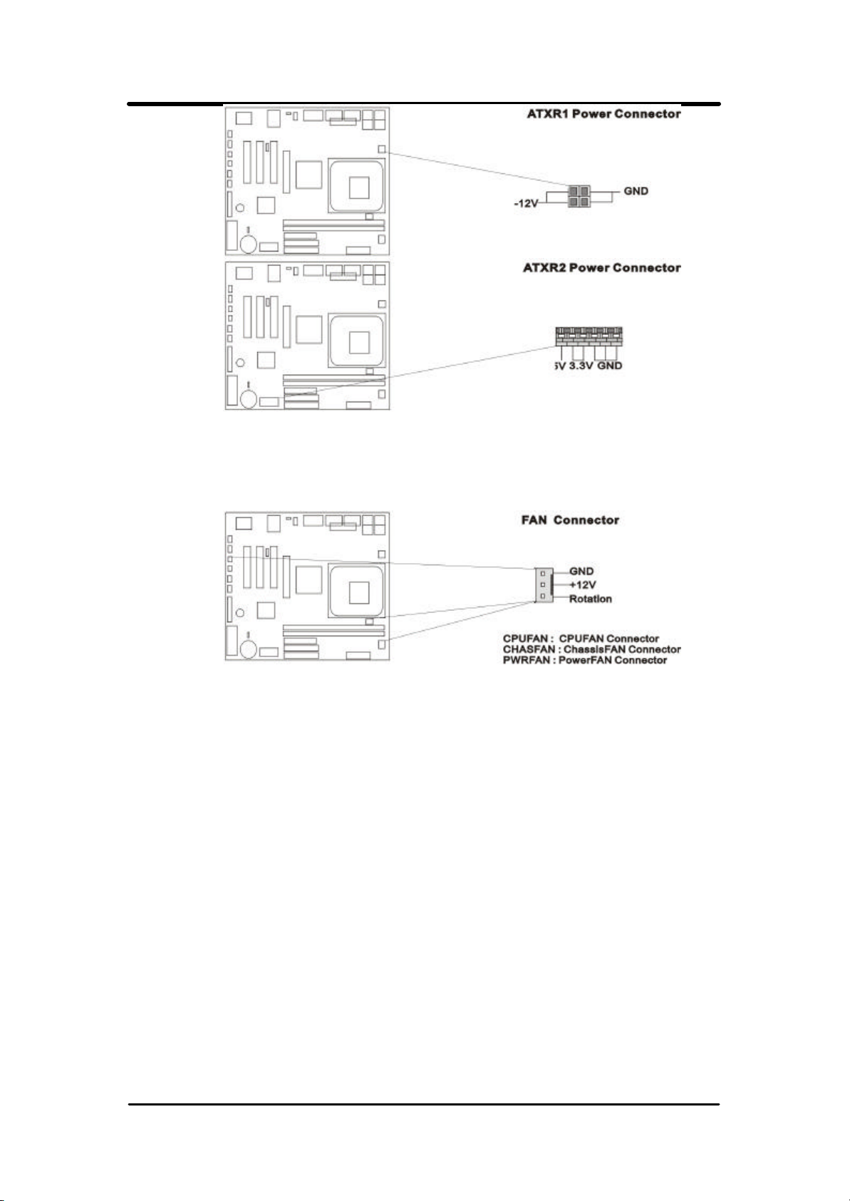
2.4.1 ATX Power Connector (20-pin CN7/J11/J10)
Make sure that the power supply is off before connecting or
disconnecting the power cable.
For Pentium 4 Power supply only, you must be insert below power
connector in your motherboard.
13
Page 14
P4VMA User’s Manual
2.4.2 CPU, Chassis /PWA Fan Connector (3-pin CPUFAN, SYSFAN/PWAFAN)
Connect the fan's plug to the board taking into consideration the
polarity of the connector.
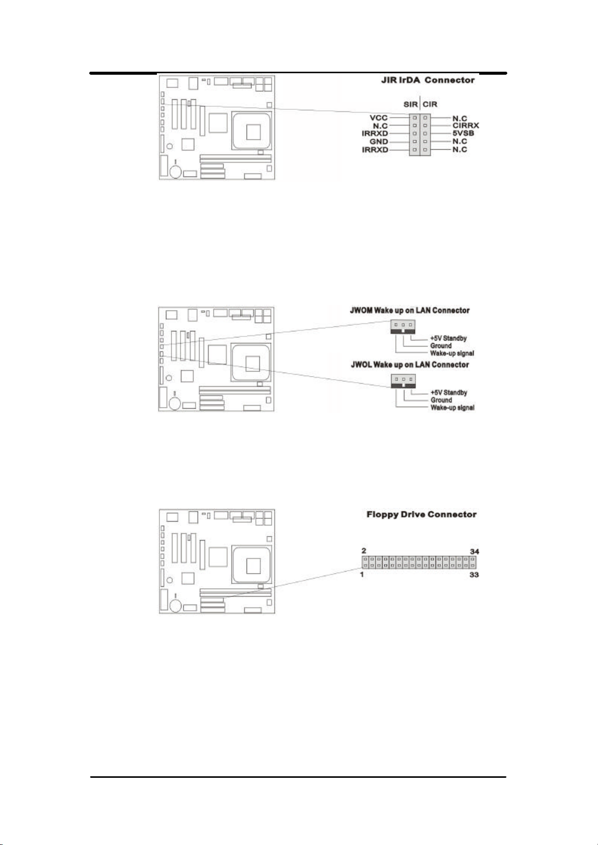
2.4.3 Infrared Connector ( 5*2-pin JIR1 )
This connector supports the optional wireless transmitting and
receiving infrared module, with this module and application software
such as Laplink or Win95 Direct Cable Connection, user can transfer
files to or from their laptops, notebooks, PDA, PCs and printers. The
connector supports IrDA (115.2Kbps, 2 meters) and ASK-IR (56Kbps).
An optional consumer infrared (CIR) set connects to the CIR and SIR
connectors simultaneously for both wireless transmitting and remote
control functions through one external infrared module. Install infrared
module onto Infrared connector and configure the setting through
“UART Mode Select” in Integrated Peripherals to select whether
UART is directed for use with COM2 or Infrared.
14
Page 15
P4VMA User’s Manual
2.4.4 Wake on LAN/Modem Connector (3-pin WOL/WOM)
The JWOL connector powers up the system when a wakeup packet or
signal is received from the network. This feature requires the Wake up
on LAN or Modem function in BIOS is set to Enabled and that your
system has an ATX power supply with at least 720mA +5V standby
power.
2.4.5 Floppy Disk Drive Connector (34-pin FLOPPY)
This connector supports the provided floppy disk drive ribbon cable.
Orient the red stripe to pin 1
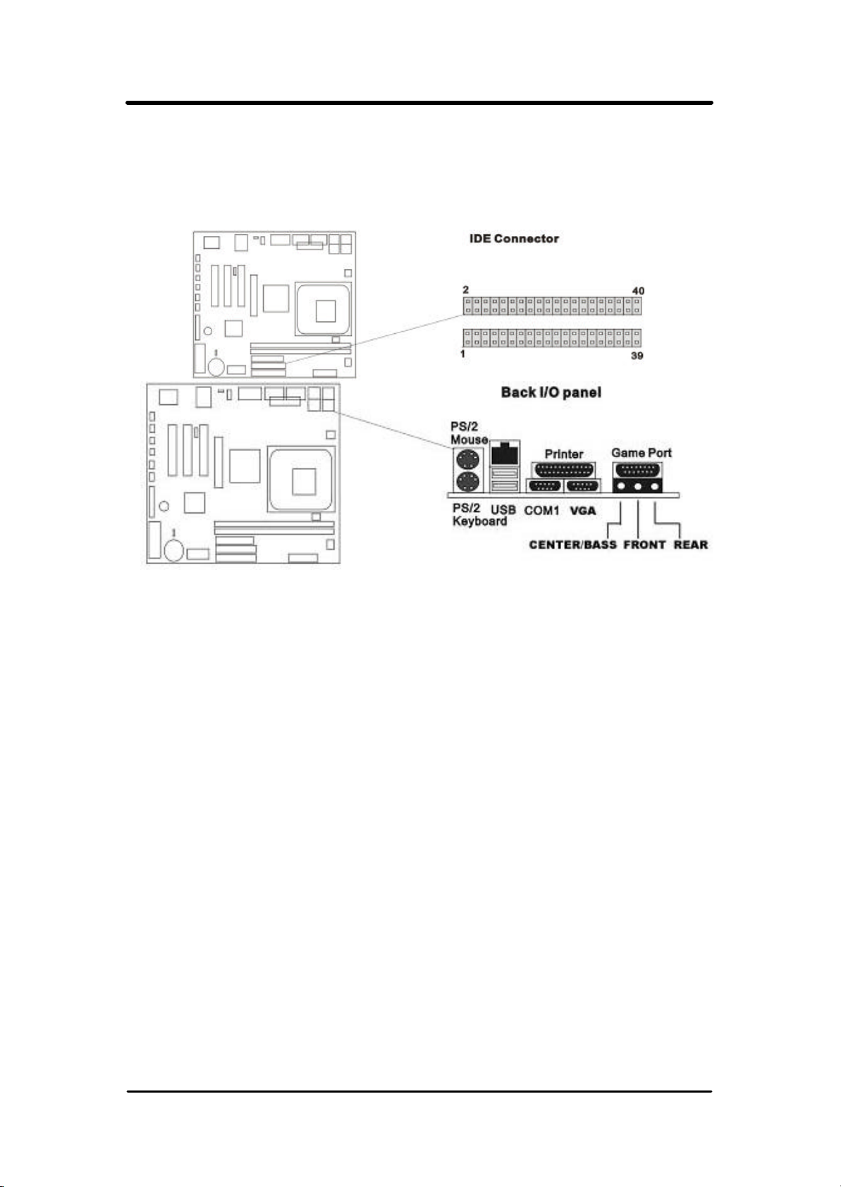
2.4.6 Primary/Secondary IDE Connector (Two 40-pin IDE)
These connectors support the provided IDE hard disk ribbon cable.
Connect your first IDE hard disk to master mode of the primary channel.
If you have second IDE device to install in your system, connect it as
slave mode on the same channel, and the third and fourth device can
be connected on secondary channel as master and slave mode
respectively.
15
Page 16
P4VMA User’s Manual
There are three connectors on the 80-pin IDE ribbon cable. The blue
connector must connect with motherboard's IDE connector and
the other connectors must connect with HDD. In order to get the better
performance the Ultra DMA 66/100 HDD must connect with 80-pin IDE
ribbon cable.
2.4.7 PS/2 Mouse Port (6-pin Mini-Din MS)
The system will direct IRQ12 to the PS/2 mouse.
2.4.8 PS/2 Keyboard Connector (6-pin Mini-Din KB)
This connection is for a standard keyboard using a PS/2 plug. You may
use a Din to Mini-Din adapter on standard AT keyboards.
2.4.9 VGA Connector (15-pin D-sub.)
This connector is for standard VGA port on board.
2.4.10 Serial Port
This connection is for standard serial port COM1, and JCOM2 jumper add-in.
2.4.11 Printer Port (25-pin D-Sub. PRINTER)
You can enable the parallel port and choose the IRQ through the
“Onboard Parallel Port ” setting in Integrated Peripherals of the CMOS
SETUP UTILITY.
16
Page 17
P4VMA User’s Manual
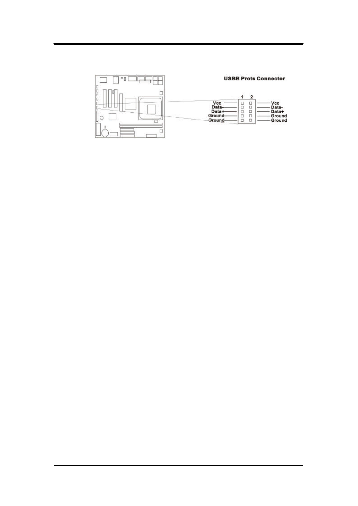
2.4.12 USB Connectors (USB & USB1,2)
You can attach USB devices to the USB or USB1,2 connector.
2.4.13 LAN Connector
The LAN connector is used to attach RJ-45 cable. For
100Base-TX,you network cable must be category 5, twisted-pair
wiring with RJ-45 connector. If you plan on running the adapter at
100Mbps, it must be connected to a 100Baes -TX Hub. For 10Base-T,
use category 3,4 or 5 twisted-pair wiring. Pls. enable VIA -3034 On
Chip LAN item from BIOS Setup before using.
2.4.14 ACT/LINK LED (Green)
This LED lights when there is network packets sent or received
through the RJ-45 port. It also lights to indicate a successful network
connection and remains steady if the connection is stable. The rate of
flashing is proportional to the amount of network traffic.
2.4.15 Speed LED (Orange)
This LED lights when connection is made to a 100Base-TX or
10Base-T host.
2.4.16 Game/MIDI Port
The Game/MIDI Port connector is used to attach a joystick for game
interaction or to attach an external MIDI device for playback, mixing, or
recording.
2.4.17 Center/Bass phone jack
The Center/Bass phone-jack provides the Center audio outputs for
the left and right stereo channels.
2.4.18 Front phone jack
The Front phone -jack provides the Front audio outputs for the left and
right stereo channels.
17
Page 18
P4VMA User’s Manual
2.4.19 Rear phone jack
The Rear phone-jack provides the Rear audio outputs for the left and
right stereo channels.
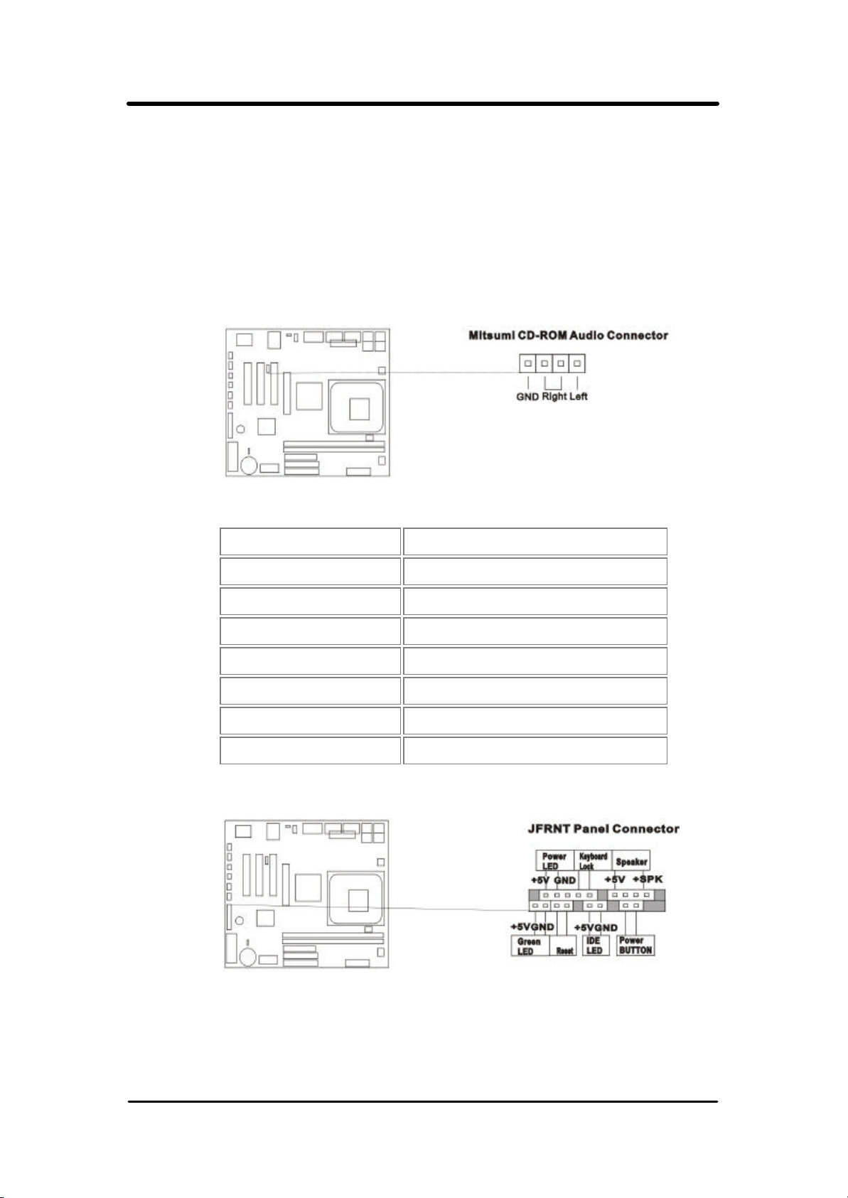
2.4.20 CD_IN Audio cable (4-pin Connector)
The CD_ROM Audio connector is used to connect the audio cable
from either an ATAPI IDE or Sony CD -ROM drive for playback, mixing,
and recording.
2.4.21 Panel Connection (24-pin JFRNT)
JFRNT Connector Function
GREENLED Suspend Mode LED
PWRLED Power LED
KEYLK Keylock Switch
SPKR Speaker
RESET Reset Switch
IDELED HDD LED
PWRBNT ATX Power Button Connector
WARNING: To avoid the system from failing, turn off the power before
connecting any devices to the system.
18
Page 19
P4VMA User’s Manual
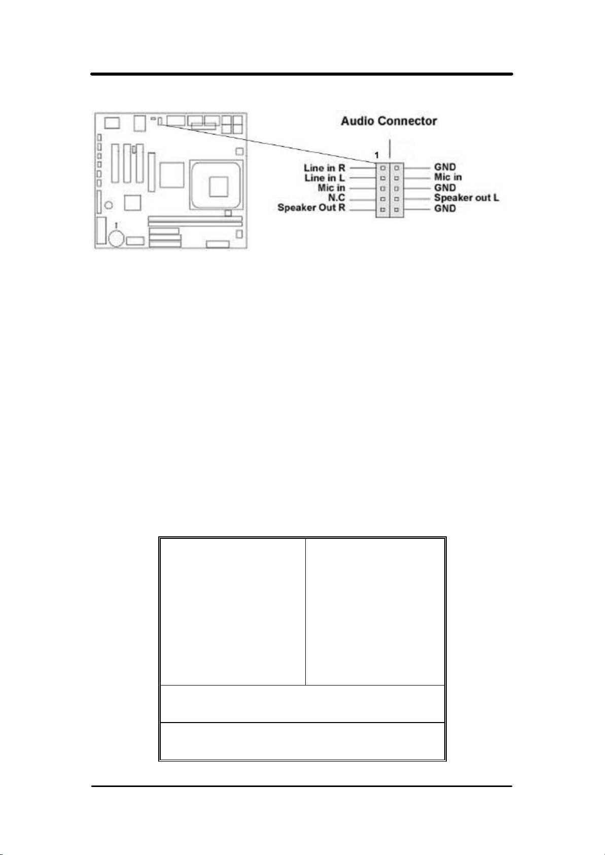
2.4.22 Audio Extra function connector setting (J12)
Chapter 3. BIOS Setup
3.1 CMOS Setup Utility
To activate CMOS Setup, press <DEL> key immediately after you turn
on the system. The following message “Press DEL to enter SETUP”
should appear in the lower left hand corner of your screen.
When you enter the CMOS Setup Utility, the Main Menu will be displayed
(Figure 3-1). You can use arrow keys to select your function, press <
Enter> key to accept the selection and enter the sub-menu.
Figure 3-1. CMOS Setup Utility Main Screen
Phoenix – AwardBIOS CMOS Setup Utility
>Standard CMOS Features >Frequency/Voltage Control
>Advanced BIOS Features Load Fail-Safe Defaults
>Advanced Chipset Features
>Integrated Peripherals
>Power Management Setup Set User Password
>PnP / PCI Configurations Save & Exit Setup
Load Optimized Defaults
Set Supervisor Password
>PC Health Status Exit Without Saving
Esc : Quit ↑ ↓ → ← : Select Item
F10 : Save & Exit Setup
Time, Date,
Hard Disk Type...
19
Page 20

P4VMA User’s Manual
Sub-Menu
Note that a right pointer symbol appears to the left of certain fields. This
pointer indicates that a sub-menu can be launched from this field. A
sub-menu contains additional options for a field parameter. To call up a
sub-menu, simple move the highlight to the field and press <Enter>. The
sub-menu will then immediately appear. Use the legend keys to enter
values and move from field within a sub-menu just as you would within a
menu. Use the <Esc> key to return to the main menu.
3.2 Standard CMOS Features
With the sub-menu (Figure 3-2), you can setup the; system date, system time,
hard and floppy drive type, and display adapter type. Pleas e refer to your
equipment specification when changing the setup. Use arrow keys to highlight
items, and use <PageUp>, <PageDown>, <+>, or <-> keys to scroll
through the available options.
Figure 3-2. Standard CMOS Features Screen
Phoenix – AwardBIOS CMOS Setup Utility
Standard CMOS Features
Date ( mm : dd : yy ) Fri, Jan 1 1999 Item Help
Time ( hh : mm: ss )
>IDE Primary Master Press Enter 4403 MB
>IDE Primary Slave Press Enter None year and century
>IDE Secondary Master Press Enter None
>IDE Secondary Slave Press Enter None
Drive A 1.44M, 3.5 in.
Drive B None
Video EGA/VGA
Halt On All Errors
Base Memory 640K
Extended Memory 14336K
Total Memory 15360K
1 : 28 : 42
Menu Level >
Change the day,
month,
↑ ↓ → ←: Move Enter : Select +/-/PU/PD : Value F10 : Save ESC : Exit F1 : General Help
F5 : Previous Value F6 : Fail-Safe Defaults F7 : Optimized Defaults
20
Page 21

P4VMA User’s Manual
3.2.1 Date
To assign the system date, the format is “mm.dd.yy”. The input range for the
Month is 1-12. Range for Date is 1-31. Range for Year is 1994-2079. System
BIOS will calculate the day of the week automatically.
3.2.2 Time
To assign the system time, the format is “hh:mm:ss”. The setting is in
military time. When entering 2:34pm enter “14:34:00”.
3.2.3 Hard Disks Setting
The BIOS supports Dual-Channel PIO and PCI Bus Master IDE ports.
Each port supports one master and one slave hard drive. You can use
<Enter> or <PageUp> or <PageDown> key to change hard
drive type. Incorrect setting may result in boot up error or system hang.
If your hard disk drive is not listed, you can select “Manual” mode to
define your own drive manually. We recommend that you select Type
“AUTO” for all drives. The BIOS will auto-detect the hard disk drive and
CD-ROM drive at the POST stage.
If your hard disk drive is a SCSI device, please select “None” for your
hard drive setting.
Phoenix – AwardBIOS CMOS Setup Utility
IDE Primary Master
IDE HDD Auto-Detection
IDE Primary Master Auto Menu Level >>
Access Mode Auto To auto-detect the
Capacity 4303 MB HDD's size, head… on
Cylinder 8894 This channel
Head 15
Precomp 0
Landing Zone 8893
Sector 63
Press Enter Item Help
↑ ↓ → ←: Move Enter : Select +/-/PU/PD : Value F10 : Save ESC : Exit F1 : General Help
F5 : Previous Value F6 : Fail-Safe Defaults F7 : Optimized Defaults
21
Page 22

P4VMA User’s Manual
3.2.4 Floppy Drives A&B Setting
Select your floppy disk drive type. Options are 360KB (5.25”), 720KB
(3.5”), 1.2MB (5.25”), 1.44MB (3.5), 2.88MB (3.5”).
3.2.5 Video Display Adapter Setting
Select the display adapter type for your system. Options are EGA/VGA,
MONO, CGA40 and CGA80.
3.2.6 Halt On
This function allows the system to halt when an error is detected during
Power-On Self-Test.
3.3 Advanced BIOS Features Setup
The sub-menu (Figure 3-3) includes all AWARD enhanced functions. The
correct setting can enhance boot up efficiency. You can assign system
speed, setup sequence, typematic and system password setting. You can
enter <F1> key for help on highlighted topics. If you want to restore
values before the changes you just made, press <F5> key. If you want
to restore default value, press <F6> or <F7> key.
22
Page 23

P4VMA User’s Manual
Rate (Chars/Sec)
Figure 3-3. Advanced BIOS Features Screen
Virus Warning Disabled Item Help
Phoenix – AwardBIOS CMOS Setup Utility
Advanced BIOS Features
CPU L1 & L2 Cache
CPU L2 Cache Ecc Checking Disabled
Quick Power On Self Test Enabled
First Boot Device HDD-0
Second Boot Device Floppy
Third Boot Device SCSI
Boot Other Device Enabled
Swap Floppy Drive Disabled
Boot Up Floppy Seek Enabled
Boot Up NumLock Status
Typematic Rate Setting Disabled
X Typematic
X Typematic Delay (Msec) 250
Security Option
OS Select For DRAM > 64MB
Video BIOS Shadow
Small Logo(EPA) Show
Enabled
On
6
Setup
Non-os2
Enabled
Enabled
Menu Level >
↑ ↓ → ←: Move Enter : Select +/-/PU/PD : Value F10 : Save ESC : Exit F1 : General Help
F5 : Previous Value F6 : Fail-Safe Defaults F7 : Optimized Defaults
( Scroll down to see more items , as shown here )
3.3.1 Virus Warning
When enabled, the BIOS will monitor the boot sector and the partition
table on the hard drive for any attempt to modify. If an attempt is
detected, the BIOS will halt the system and prompt the warning
message. Select “Disabled” if you are installing a new operating
system.
3.3.2 CPU L1 & L2 Cache
These options are to enable or disable CPU Internal (L1) Cache,
or (L2) Cache.
3.3.2 CPU L2 Cache Ecc Checking
Enabled or Disabled to L2 Cache memory ECC check function.
23
Page 24

P4VMA User’s Manual
3.3.3 Quick Power On Self Test
Select “Enabled” to speed up time required to complete Power-On
Self-Test.
3.3.4 First/Second/Third Boot Device & Boot Other Device
This option allows user to assign boot sequence of the system.
Available options are Floppy, HDD, CD-ROM, SCSI, LAN, LS120 and
ZIP100. Set " Boot Other Device" to Enabled if you wish to boot from
another device.
3.3.5 Swap Floppy Drive
When enabled, physical drive A will be assigned to logical drive B, and
physical drive B will be assigned to logical drive A.
3.3.6 Boot Up Floppy Seek
The system will detect and verify operation of the floppy drive type.
3.3.7 Boot Up Numlock Status
The option allows the <NumLock> key to be activated after system
boot up.
3.3.9 Typematic Rate Setting
Select “Enabled” to configure “Typematic Rate” and “Typematic
Delay” functions.
3.3.10 Typematic Rate
Use this option to set the rate at which a character keeps repeating
while you hold down a key.
3.3.11 Typematic Delay
Select “Enabled” to set the length of delay before key strokes to repeat.
Available options are “250”, “500”, “750”, and “1000”.
24
Page 25

P4VMA User’s Manual
3.3.12 Security Option
You can select whether the password is required every time the system
boots or only when you enter the Setup. You can assign “Supervisor
Password” and "User Password" in the main CMOS Setup Utility
Screen.
3.3.15 OS Select for DRAM > 64MB
If you are using OS/2 operating system and installed memory is larger
than 64MB. You need to have the setting in the enable mode.
3.3.16 Video BIOS Shadow
Disabled or Enabled VGA card BIOS Data shine upon to RAM..
3.3.17 Small Logo(EPA) Show
When you select “ Enabled” the screen shows as “Energy Star”
picture at the front side up right. “Disabled” is close this picture .
3.4 Advanced Chipset Features Setup
These settings are intended for the Advanced Chipset function on the
motherboard. Fine-tuning these options enhances the performance of the
system.
25
Page 26

P4VMA User’s Manual
Figure 3.4-Advanced Chipset Features Screen
Phoenix – AwardBIOS CMOS Setup Utility
Advanced Chipset Features
→DRAM Clock/Drive Control
→AGP & P2P Bridge Control
→CPU & PCI Bus Control
Memory Hole [Disabled ]
System bios cacheable [Enabled ]
Video RAM cacheable [Enabled ]
Delay Prior to Thermal
VGA Share Memory Size
FB Address Conversion
FB Page Close Prediction
Memory Parity/Ecc check
[ press Enter ] Item Help
[ press Enter ]
[ press Enter ]
Menu Level
[16 Min ]
[32 Min ]
[Disabled ]
[Disabled ]
[Disabled ]
↑ ↓ → ←: Move Enter : Select +/-/PU/PD : Value F10 : Save ESC : Exit F1 : General Help
F5 : Previous Value F6 : Fail-Safe Defaults F7 : Optimized Defaults
26
Page 27

P4VMA User’s Manual
3.4.1 DRAM Clock/Drive Control
Current FSB Frequency 100 MHz Item Help
Phoenix – AwardBIOS CMOS Setup Utility
DRAM Clock/Drive control
Current DRAM Frequency 133 MHz
DRAM Clock [By SPD]
DRAM Timing [By SPD]
X SPRAM CAS Latency 2.5
X Bank Interleave [ Disabled ]
X Precharge to Active (Trp) 3T
X Active to Precharge (Tras) 6T
X Active to CMD (Trcd)
X DRAM Command Rate 2T Command
X DRAM Burst Len 4
CPU read DRAM Mode [Fast]
3T
Menu Level
↑ ↓ → ←: Move Enter : Select +/-/PU/PD : Value F10 : Save ESC : Exit F1 : General Help
F5 : Previous Value F6 : Fail-Safe Defaults F7 : Optimized Defaults
3.4.11 Current FSB Freque ncy
The FSB frequency provides settings for the CPU . Auto Detect,100MHz or
133MHz FSB frequency can be selected with this items.The over specification
is not recommended.Default setting in the 100MHz FSB Frequency.
3.4.12 Current DRAM Freque ncy
The DIMM memory frequency provides settings for the DDRRAM. Auto
Detect,100MHz or 133MHz frequency can be selected with this items.The over
specification is not recommended.Default setting in the 100MHz FSB
Frequency
27
Page 28

P4VMA User’s Manual
3.4.13 DRAM Clock
If your DIMM memory has SPD (Serial Presence Detect) 8-pin IC on module,
you can set this option to “By SPD”. System will set your SDRAM clock and
timing from the SPD IC. If the option set as ”Manual”, DRAM clock and timing
must be set from items below:
3.4.14 DRAM Timeing
If your DIMM memory has SPD (Serial Presence Detect) 8-pin IC on module,
you can set this option to “By SPD”. System will set your SDRAM clock and
timing from the SPD IC. If the option set as ”Manual”, DRAM clock and timing
must be set from items below:
3.4.14 SPRAM CAS Latency
This controls the latency between the SDRAM read command and
the time that the data actually becomes available.
3.4.15 Bank Interleave
When you select “Enabled” mode, you can set active to Precharge SDRAM
timing delay.
3.4.16 Precharge to Active (Trp)
When you select “2T or 3T” mode, you can set active to Precharge SDRAM
timing delay.
3.4.17 Precharge to Active (Trcd)
When you select “5T or 6T” mode, you can set active to Precharge SDRAM
timing delay.
3.4.18 DRAM Burst Len
This controls the latency between the SDRAM read command and
the Len that the memory actually becomes available.
3.4.19 DRAM Command Rate
This controls the latency between the SDRAM read command and
the time that the data actually becomes available.
28
Page 29

P4VMA User’s Manual
3.4.20 CPU read DRAM Mode
This controls the latency between the CPU read command and the time that
the data actually becomes available.
3.4.2 AGP & P2P Bridge control
AGP Aperture Size [ 64M ] Item Help
Phoenix – AwardBIOS CMOS Setup Utility
AGP & P2P Bridge control
AGP Driving Control [ Auto ]
X AGP Driving Value
AGP Fast write [ Disabled ]
AGP Master 1ws write [ Disabled ]
AGP Master 1ws Read [ Disabled ]
↑ ↓ → ←: Move Enter : Select +/-/PU/PD : Value F10 : Save ESC : Exit F1 : General Help
F5 : Previous Value F6 : Fail-Safe Defaults F7 : Optimized Defaults
DA
Menu Level
3.4.21 AGP Aperture Size
Choose 32, 64MB. Memory -mapped, graphics data structures can
reside in the Graphics Aperture.
3.4.22 AGP Mode
Choose 1x, 2x. AGP mode, graphics data structures can reside in
the Graphics Aperture.
3.4.23 AGP Driving Control
This controls the latency between the AGP Driver command and the time
that the data actually becomes available.
3.4.24 AGP Driving Value
This controls the Value between the AGP Driver command and the time
that the data actually becomes available.
29
Page 30

P4VMA User’s Manual
3.4.25 AGP Fast write
This controls the latency between the AGP read command and the time
that the data actually becomes available.
3.4.26 AGP Master 1ws write
This controls the latency between the AGP write command and the time
that the clock wait data actually becomes available.
3.4.27 AGP Master 1ws Read
This controls the latency between the AGP read command and the time
that the clock wait data actually becomes available.
3.4.3 CPU & PCI Bus control
Phoenix – AwardBIOS CMOS Setup Utility
CPU & PCI Bus control
CPU to PCI write Buffer [ Enabled ] Item Help
PCI Master 0 ws write [ Enabled ]
PCI Delay Transaction [ Enabled ]
Menu Level
↑ ↓ → ←: Move Enter : Select +/-/PU/PD : Value F10 : Save ESC : Exit F1 : General Help
F5 : Previous Value F6 : Fail-Safe Defaults F7 : Optimized Defaults
3.4.31 CPU & PCI write Buffer
When enabled, up to four D words of data can be written to the PCI bus
without interrupting the CPU. When disabled,a write buffer is not used
and the CPU read cycle will not be completed until the PCI bus signals
that it is ready to receive the data.
3.4.32 PCI Master 0 ws write
When enabled, writes to the PCI bus are command with zero wait states.
3.4.33 PCI Delay Transaction
The chipset has an embedded 32-bit posted write buffer to support delay
transaction cycles. Select Enabled to support compliance with PCI specification
version 2.1.
30
Page 31

P4VMA User’s Manual
3.4.4 Memory Hole
Enabling this feature reserves 15MB to 16MB memory address space
to ISA expansion cards that specifically require this setting. This makes
the memory from 15MB and up unavailable to the system. Expansion
cards can only access memory up to 16MB.
3.4.5 System bios cacheable
Allows the system BIOS to be cached for faster system performance.
3.4.6 Video RAM Cacheable
Allows the video RAM to be cached for faster video performance.
3.4.7 Delay Prior to Thermal
When you system temperature higher, you can set the DRAM access
time slowdown between on 4 min – 32 min delay.
.
3.4.8 VGA Share Memory Size
When you system VGA memory , you can set the share between on 4
M – 32M memory.
3.4.9 FB Address Conversion
Adds a FB Address Conversion to function.
3.4.10 FB Page Close Prediction
Adds a FB Page Close Prediction to function
3.4.11 Memory Parity/Ecc check
Enable adds a Parity check to the boot -up memory tests. Select
Enabled only if the system DRAM contains parity .
31
Page 32

P4VMA User’s Manual
3.5 Integrated Peripherals
You can control Input and Output functions from this screen.
Phoenix – AwardBIOS CMOS Setup Utility
3.5.1 Via On chip IDE Device
→Via On chip IDE Device [ Press Enter ] Item Help
Figure 3-5 Integrated Peripherals
Integrated Peripherals
→Via On chip PCI Device [ Press Enter ]
→Super Io Device [ Press Enter ]
Init Display First
Onchip USB Controller
USB Keyboard Support
IDE HDD Block Mode
↑ ↓ → ←: Move Enter : Select +/-/PU/PD : Value F10 : Save ESC : Exit F1 : General Help
F5 : Previous Value F6 : Fail-Safe Defaults F7 : Optimized Defaults
Phoenix – AwardBIOS CMOS Setup Utility
Onchip IDE Channel 0 [ Enabled ] Item Help
Onchip IDE Channel 1 [ Enabled ]
IDE Prefetch Mode [ Enabled ]
Primary Master PIO
Primary Slave PIO
Secondary Master PIO
Secondary Slave PIO
Primary Master UDMA
Primary Slave UDMA
Secondary Master UDMA
Secondary Slave UDMA
[ PCI Slot ]
[ All Enabled ]
[ Disabled ]
[ Enabled ]
Via Onchip IDE Device
[ Auto ]
[ Auto ]
[ Auto ]
[ Auto ]
[ Auto ]
[ Auto ]
[ Auto ]
[ Auto ]
Menu Level
Menu Level
↑ ↓ → ←: Move Enter : Select +/-/PU/PD : Value F10 : Save ESC : Exit F1 : General Help
F5 : Previous Value F6 : Fail-Safe Defaults F7 : Optimized Defaults
32
Page 33

P4VMA User’s Manual
3.5.1 Onchinip IDE Channel 0
Select “Enabled” to activate each on-board IDE channel separately ,Select ”Disabled” ,if you install an
add-on IDE Control card.
3.5.2 Onchinip IDE Channel 1
Select “Enabled” to activate each on-board IDE channel separately ,Select ”Disabled” ,if you install an
add-on IDE Control card.
3.5.3 IDE Prefetch Mode
Enable prefetching for IDE drive interfaces that support its faster drive accesses If you are getting disk
drive errors, change the setting to omit the drive interface where the errors occur. Depending on the
configuration of your IDE subsystem, this field may not appear, and it does appear, and it does appear
when the internal PCI/IDE filed, above, is Disable.
3.5.4 Primary Master PIO
These four PIO fields let you set a PIO mode (0-4) for each of four IDE devices. When under
"Auto" mode, the system automatically set the best mode for each device
3.5.5 Primary Slave PIO
These four PIO fields let you set a PIO mode (0-4) for each of four IDE devices. When under
"Auto" mode, the system automatically set the best mode for each device
3.5.6 Secondary Master PIO
These four PIO fields let you set a PIO mode (0-4) for each of four IDE devices. When under
"Auto" mode, the system automatically set the best mode for each device
3.5.7 Secondary Slave PIO
These four PIO fields let you set a PIO mode (0-4) for each of four IDE devices. When under
"Auto" mode, the system automatically set the best mode for each device
3.5.8 Primary Master UDMA
When set to "Auto" mode, the system will detect if the hard drive supports Ultra DMA mode.
3.5.9 Primary Slave UDMA
When set to "Auto" mode, the system will detect if the hard drive supports Ultra DMA mode.
3.5.10 Secondary Master UDMA
When set to "Auto" mode, the system will detect if the hard drive supports Ultra DMA mode.
3.5.11 Secondary Slave UDMA
When set to "Auto" mode, the system will detect if the hard drive supports Ultra DMA mode.
33
Page 34

P4VMA User’s Manual
3.5.2 Via Onchip PCI Device
VIA – 3043 OnChip LAN [ Enabled ] Item Help
OnChip LAN BootRom [ Disabled ] MenuLevel >
Phoenix – AwardBIOS CMOS Setup Utility
VIA Onchip PCI Device
↑ ↓ → ←: Move Enter : Select +/-/PU/PD : Value F10 : Save ESC : Exit F1 : General Help
F5 : Previous Value F6 : Fail-Safe Defaults F7 : Optimized Defaults
3.5.21 Via—3085 AC 97 Audio
When set to "Auto" mode, the system will detect if the hard supports ac 97 audio mode.
3.5.22 Via—3086 MC 97 Modem
When set to "Auto" mode, the system will detect if the hard supports mc 97 modem mode.
3.5.3 Super IO Device
Phoenix – AwardBIOS CMOS Setup Utility
Super Io Device
Onboard FDC Controller [ Enabled ] Item Help
Onboard Serial Port1 [ 3F8/IRQ4 ] MenuLevel >
Onboard Serial Port2 [ 2F8/IRQ3 ]
UART Mode Select [ Normal ]
X UR2 Duplex Mode Half
Onboard Parallel Port
Parallel Port Mode
XECP Mode Use DMA 3
Game Port Address
Midi Port Address
Midi Port IRQ [ 10 ]
↑ ↓ → ←: Move Enter : Select +/-/PU/PD : Value F10 : Save ESC : Exit F1 : General Help
F5 : Previous Value F6 : Fail-Safe Defaults F7 : Optimized Defaults
[ 378/IRQ1 ]
[ SPP ]
[ 201 ]
[ 330 ]
( Scroll down to see more items , as shown here )
34
Page 35

P4VMA User’s Manual
3.5.31 Onboard FDC Controller
Select “Enabled” to activate the on-board FDC
Select “Disabled” to activate an add-on FDC
3.5.32 Onboard Serial Port1
Select an address and corresponding interrupt for the first/second serial port.
The default value for the first serial port is “3F8/IRQ4” and the second serial port
is “2F8/IRQ3”.
3.5.33 Onboard Serial Port2
Select an address and corresponding interrupt for the first/second serial port.
The default value for the first serial port is “3F8/IRQ4” and the second serial port
is “2F8/IRQ3”.
3.5.34 UART Mode Select
Select to activate the Infrared transfer function.
3.5.35 UR2 Duplex Mode
Select to activate the Infrared transfer function. This default setting is “Normal“.
3.5.36 Onboard Parallel Port
Select address and interrupt for the Parallel port.
3.5.37 Parallel Port Mode
Select an operating mode for the parallel port. Mode options are SPP, EPP,
ECP and ECP+EPP.
3.5.38 ECP Mode Use DMA
Select a DMA channel if parallel port is set as ECP or ECP+EPP.
3.5.39 Game Port Address
This field sets the address of the onboard game port connector.
35
Page 36

P4VMA User’s Manual
3.5.40 Midi Port Address
This field is used to select the midi port's address. If you have selected the
midi port's address, you may select its IRQ in the " Midi Port IRQ ".
3.5.41 Midi Port IRQ
This field is used to select the midi port's IRQ.
3.6 Power Management Setup
Power management decreases power usage under the pre-defined
standby time range.
Figure 3-6. Power Management Setup Screen
Phoenix – AwardBIOS CMOS Setup Utility
Power Management Setup
ACPI function [ Enabled ] Item Help
ACPI Suspend Type S1 (POS) MenuLevel >
Power Management User Define
HDD Power Down [ Disabled ]
Suspend Mode
Video Off Option [Suspend → off]
Video Off Method [ V/H SYNC + Blank ]
MODEM Use IRQ [ 3 ]
Run VGABIOS if S3 Resum e
PWRON After PWR-Fail [ off ]
→IRQ/Event Activity Detect [ Press Enter ]
[ Disabled ]
[ AUTO ]
↑ ↓ → ←: Move Enter : Select +/-/PU/PD : Value F10 : Save ESC : Exit F1 : General Help
F5 : Previous Value F6 : Fail-Safe Defaults F7 : Optimized Defaults
( Scroll down items , as shown here )
3.6.1 ACPI Function
This item allows you to enable or disable the function of Advanced
Configuration and Power Interface which offers improved power
management .
36
Page 37

P4VMA User’s Manual
3.6.2 ACPI Suspend Type
This field is used to select the type of Suspend function.
S1 (POS): Enables the Power On Suspend function.
S3 (STR): Enables the Suspend to RAM function. Refer to Appendix A.
3.6.3 Power Management
Mini Saving System starts power saving function when the
Max Saving System starts power saving function when the
inactivity period exceeds 1 hour.
inactivity period exceeds 1 min.
User
Defined
Allows user to define the inactivity period before
power saving function activates,
3.6.4 HDD Power Down
This instructs hard drives to shut off while in the Power Management
modes.
3.6.5 Suspend Mode
System further shuts down all devices except for CPU itself. This is the
third level of Power Management.
3.6.6 Video Off In Option Video Off Option
When enabled, this feature allows the VGA adapter to operate in a
power saving mode.
Always On Monitor will remain on during power
saving modes.
Suspend --> Off Monitor blanked when the systems enters
the Suspend mode.
All Modes -->
Off
Monitor blanked when the system enters
any power saving mode.
37
Page 38

P4VMA User’s Manual
3.6.7 Video Off Method
This field defines the video off features. The following options are
available: DPMS OFF, DPMS Reduce ON, Blank Screen, V/H
SYNC+Blank, DPMS Standby, and DPMS Suspend. The DPMS
(Display Power Management System) features allow the BIOS to
control the video display card if it supports the DPMS feature.
3.6.8 MODEM Use IRQ
This item tells the Power Management BIOS which IRQ is assigned to
the installed MODEM. Option is NA, 3, 4, 5, 7, 9, 10 and 11.
3.6.9 Run VGABIOS if S3 Resume
Allows the VGABIOS if S3 to be cached for faster system Resume
performance.
3.6.10 PWRON After PWR-Fail
When set to “Delay 4 Sec ”, the power button has a dual function where pressing
less than 4 seconds will place the system in sleep mode and shut down the
system when the button is held more than 4 seconds. “Instant-Off”, the system
will be shut down right away when the power button is pressed.
38
Page 39

P4VMA User’s Manual
3.6.11 IRQ/Event Activity Detect
VGA [ OFF ] Item Help
LPT & COM [ LPT/COM ] MenuLevel >
Phoenix – AwardBIOS CMOS Setup Utility
IRQ/Event Activity Detect
HDD & FDDt [ ON ]
PCI Master [ OFF ]
Power On by PCI Card
Modem Ring Resume [ Disabled ]
RTC Alarm Resume [ V/H SYNC + Blank ]
Xdate (of Month)
XResume Time (hh:mm:ss)
→IRQs Activity Monitoring [ Press Enter ]
[ Disabled ]
0
0:0:0
↑ ↓ → ←: Move Enter : Select +/-/PU/PD : Value F10 : Save ESC : Exit F1 : General Help
F5 : Previous Value F6 : Fail-Safe Defaults F7 : Optimized Defaults
3.6.11.1 VGA
When set to On, any event occurring at a VGA port will awaken a system which has been
powered down.
3.6.1.2 LPT & COM
When set to On, any event occurring at a LPT (printer) / COM (serial) port will awaken a
system which has been powered down.
3.6.1.3 HDD & FDD
When set to On, any event occurring at a Hard Disk or floppy drive port will awaken a
system which has been powered down.
3.6.1.4 PCI Master
When set to On, any event occurring to the DMA controller will awaken a system which
has been powered down.
39
Page 40

P4VMA User’s Manual
3.6.1.5 Power On by PCI Card
This allows you to remotely power up your system through your PCI interface by sending
a signal.
3.6.1.6 Modem Ring Resume
This allows you to remotely your system through your Modem interface by sending a
signal.
3.6.1.7 RTC Alarm Resume
Set this option to enable or disable the RTC Alarm to Wake Up the system which is set at
3.6.1.8 Data (of Month)
Set these options to specify the RTC Alarm time on Date / Hour / Minute /Second.
3.6.1.9 Resume Time (hh:mm:ss)
Set these options to specify the RTC Alarm time on Date / Hour / Minute /Second.
soft Off.
40
Page 41

P4VMA User’s Manual
3.6.2 IRQs Activity Monitoring
Primary INTR [ ON ] Item Help
IRQ3 (COM 2) [ Enabled ] MenuLevel >
Phoenix – AwardBIOS CMOS Setup Utility
IRQs Activity Monitoring
IRQ4 (COM 1) [ Enabled ]
IRQ5 ( LPT2 ) [ Enabled ]
IRQ6 ( Floppy Disk ) [ Enabled ]
IRQ7 ( LPT1 ) [ Enabled ]
IRQ8 ( RTC Alarm ) [ Disabled ]
IRQ9 ( IRQ2 Redir ) [ Disabled ]
IRQ10 ( Reserved ) [ Disabled ]
IRQ11 ( Reserved ) [ Disabled ]
IRQ12 ( PS/2 Mouse ) [ Enabled ]
IRQ13 ( Coprocessor ) [ Enabled ]
IRQ14 ( Hard Disk ) [ Enabled ]
IRQ15 ( Reserved ) [ Disabled ]
↑ ↓ → ←: Move Enter : Select +/-/PU/PD : Value F10 : Save ESC : Exit F1 : General Help
F5 : Previous Value F6 : Fail-Safe Defaults F7 : Optimized Defaults
( Scroll down items , as shown here )
41
Page 42

P4VMA User’s Manual
3.7 PNP/PCI Configurations Setup
Figure 3.7 PNP/PCI CONFIGURATIONS SETUP
CMOS Setup Utility - Copyright ( C ) 1984 - 1999 Award Software
PnP / PCI Configurations
PnP OS Installed [ No ] Item Help
Reset Configuration [ Disabled ]
Resources Controlled By [ Auto (ESCD) ]
X IRQ Resources
PCI/VGA Palette Snoop
Assign IRQ For VGA
Assign IRQ For USB
Press Enter
[ Disabled ]
[ Enabled ]
[ Enabled ]
Menu level
Select Yes if you are
using a Play CaPable
operating system
select No if you need
the BIOS to configure
non-boot devices .
↑ ↓ → ←: Move Enter : Select +/-/PU/PD : Value F10 : Save ESC : Exit F1 : General Help
F5 : Previous Value F6 : Fail-Safe Defaults F7 : Optimized Defaults
3.7.1 PnP OS Installed
This field allows you to use a Plug-and-Play (PnP) operating system.
Please set it as "No " if the operating system has no PnP function or to avoid reassigning
the IRQs by the operating system.
3.7.2 Reset Configuration Data
In case a conflict occurs after you assign the IRQs or after you
configure your system, you can enable this function to allow your
system to automatically reset your configuration and reassign the IRQs,
DMAs, and I/O address.
3.7.3 Resources Controlled By
Default setting is “Auto (ESCD)”. This setting allows the BIOS to self
detect setting and Plug-and-Play devices during start up. The user can
select and configure IRQs under "Manual" mode.
42
Page 43

P4VMA User’s Manual
3.7.4 IRQ Resources
CMOS Setup Utility - Copyright ( C ) 1984 - 1999 Award Software
IRQ-3 assigned to PCI Device Item Help
IRQ-4 assigned to PCI Devic Menu Level >
IRQ Resources
IRQ-5 assigned to PCI Device
IRQ-7 assigned to PCI Device Legacy ISA for evices
IRQ-9 assigned to PCI Device compliant with the
IRQ-10 assigned to PCI Device original PC AT bus
IRQ-11 assigned to PCI Device Specification, PCI/ISA
IRQ-12 assigned to PCI Device PnP for devices
IRQ-14 assigned to PCI Device Compliant with the
IRQ-15 assigned to PCI Device Plug & Play standard
↑ ↓ → ←: Move Enter : Select +/-/PU/PD : Value F10 : Save ESC : Exit F1 : General Help
F5 : Previous Value F6 : Fail-Safe Defaults F7 : Optimized Defaults
Whether designed for
PCI OR ISA bus
architecture
3.7.5 PCI/VGA Palette Snoop
Enable this option to correct screen color shifts, when there is a combination of VGA
cards, accelerator cards, or MPEG cards present.
3.7.5 Assign IRQ For VGA
The Enabled option allows the BIOS to auto-route an IRQ for use by a VGA card. While
most of the VGA cards do not need the IRQ assignment, certain VGA cards may need it.
3.7.6 Assign IRQ For USB
This item can be found when "OnChip USB" is enabled from Advanced Chipset Features menu.
When this item is Enabled, the system automatically assigns an IRQ for the USB device connected
to your sy stem. However, if you are not using USB devices and an ISA slot required an IRQ address,
set this function to
43
Page 44

P4VMA User’s Manual
3.7.4 PCI/VGA Palette Snoop
Enable this option to correct screen color shifts, when there is a
combination of VGA cards, accelerator cards, or MPEG cards present.
3.8 PC Health Status
CMOS Setup Utility - Copyright ( C ) 1984 - 1999 Award Software
Shutdown Temperature [ 60°C/140°F ] Item Help
Vcore (v) 1.76 v Menu Level
Figure 3.8 PC Health Status
PC Health Status
Vcmos (v) 2.51 v
Vcc 3 (v) 3.32 v
Vcc (v) 5.02 v
+12 (v) 11.84 v
5VSB (v) 0.94 v
VBAT (v) 2.91 v
CPU Temperature 2.94 v
System Temperature 28°c
PWR FAN 31°c
CPU FAN 2445RMP
SYS FAN 0 RMP
↑ ↓ → ←: Move Enter : Select +/-/PU/PD : Value F10 : Save ESC : Exit F1 : General Help
F5 : Previous Value F6 : Fail-Safe Defaults F7 : Optimized Defaults
3.8.1 Shutdown Temperature
When you select “ enable “, the CPU working temperature at over setting. Should
be shutdown PC . “ Disabled “ is close this functions.
3.8.2 Vcore, Vcc3, +5V, +12V, -12V,-5V, VBAT & 5VSB (xx.xxV)
The onboard hardware monitor is able to detect the voltage output by
the voltage regulators. These values refresh upon any key entry. The
function is optional.
44
Page 45

P4VMA User’s Manual
3.8.3 Current System & CPU Temperature (xx°C/xx°F)
The onboard hardware monitor is able to detect the temperatures of
motherboard and CPU. These values refresh upon any key entry. The
function is optional.
3.8.4 Current CPUFAN , CHASFAN & PWRFAN Speed (xxxxRPM)
The onboard hardware monitor is able to detect chassis fan speed,
CPU fan and PWR fan speed in Rotations Per Minute (RPM). These
values refresh upon any key entry in the BIOS setup screen. The
function is optional.
3.9 Frequency Control
Figure 3.9 Frequency Control
CMOS Setup Utility - Copyright ( C ) 1984 - 1999 Award Software
Frequency Control
CPU Clock Ratio X 8 Item Help
Auto Detect PCI Clk Enabled Menu Lev el >
Spread Spectrum
CPU Host/3V66/PCI Clock Default
Disabled
↑ ↓ → ←: Move Enter : Select +/-/PU/PD : Value F10 : Save ESC : Exit F1 : General Help
F5 : Previous Value F6 : Fail-Safe Defaults F7 : Optimized Defaults
3.9.1 CPU Clock Ratio
The Ratio of some latest Intel Corporation fixes CPUs and VIA so the
Ratio cannot be changed with the setting. If it did not fix by CPU
manufacturer, it may be changed with the setting. Over specification
operations are not recommended.
3.9.2 Auto Detect PCI CLK
If you have the EMI issue, set the option as Enabled, it keeps its
interference under control.
45
Page 46

P4VMA User’s Manual
3.9.3 Spread Spectrum
Using the setting “ Enabled “, for EMI testing will increase the system stability.
The default setting is “ Disabled “.
3.9.2 CPU Host/3v66/PCI Clock
Choose Default, 100, 103, 105, 107,109,111, 114, 117,120, 127, 130
MHz for the external frequency of your CPU.
You can select Default, 66, 69,70,71,73,74,76,78,80,85,87MHz. if your
CPU is 100Mhz FSB and select Default, 100, 103, 105,
107,109,111,114,117, 120, 127 or 130 MHz if the CPU is 100Mhz FSB.
IWarning: Over specification operations are not recommended.
The frequency-mapping table of the elements:
CPU Host/3V66 PCI
100 / 66 MHz 33 MHz
103 / 69 MHz 34 MHz
105 / 70 MHz 35 MHz
107 / 71 MHz 36 MHz
109 / 73 MHz 36 MHz
111 / 74 MHz 37 MHz
114 / 76 MHz 38 MHz
117 / 78 MHz 39 MHz
120 / 80 MHz 40 MHz
127 / 85 MHz 42 MHz
130 / 87 MHz 43 MHz
3.10 Load Fail-Safe Defaults
This loads the troubleshooting default values permanently stored in the
ROM chips. These settings are not optimal and turn off all high
performance features. You should use these values only if you have
hardware problems. Highlight this option in the main menu and press
<Enter>. The message below will appear.
Load Fail-Safe Defaults (Y/N)? N
If you want to process, type <Y> and press <Enter>. The default settings
will be loaded.
46
Page 47

P4VMA User’s Manual
3.11 Load Optimized Defaults
This feature loads optimized setting from the BIOS ROM. Use the default
values as standard values for your system. Highlight this option in the main
menu and press <Enter>. The message below will appear.
Load Optimized Defaults (Y/N)? N
Type <Y> and press <Enter> to load the Setup default values.
3.12 Set Supervisor/User Password
You can assign, modify, or cancel password settings. To modify, highlight
“Set Supervisor Password” or “Set User Password” and press the <
Enter> key. The screen will prompt you (“Enter Password: ”). Enter your
password. The maximum size of the password is 8 characters. System will
prompt you to reenter the password to verify. Remember the passwords
are case sensitive.
If you want to remove the passwords, either delete passwords or pres s <
Enter> when prompting for new password.
If you want it to require password upon initial system startup and upon
entering the CMOS Setup Utility, you will need to change the selection of
the (Security Option) under (Advanced BIOS Features) to “System”.
If the setting is “Setup”, the system will only require the password you
activate CMOS Setup Utility.
3.13 Save & Exit Setup
When all the changes have been made, highlight "Save & Exit Setup" and
press <Enter>. The message below will appear:
Save to CMOS and Exit (Y/N)? N
Type "Y" and press <Enter>. The modifications you have made will be
written into the CMOS memory, and the system will reboot.
3.14 Exit Without Saving
When you do not want to save the changes you have made, highlight "Exit
Without Saving" and press <Enter>, the message below will appear:
Quit Without Saving (Y/N)? N
Type "Y" and press <Enter>. The system will reboot.
47
Page 48

P4VMA User’s Manual
Chapter 4. Driver installation
You can use the auto run menu of this CD Disc. The screen shows as you BIOS ID then
please choose your preferred mode of this installation program:
n Detect and select your motherboard type automatically.
n Select motherboard type on your own manually.
The CD Driver Disk for P4VMA Motherboard Chipset Setup includes driver for:
Install Motherboard Software
Install Ultra ATA
Install Audio Device Software
Link to < Web Site > Homepage
Browse this CD
4.1 Install Motherboard Software:
You can move your mouse choose “ INF update for Intel chipsets” then push right
button on your mouse. They can automatic detect your windows operating system
version.
4.2 Install Ultra ATA Driver:
You can move your mouse choose “ Install ATA Driver ” then push right button on
your mouse. They can automatic detect your windows operating system version.
4.3 Install Audio Device Software:
You can move your mouse choose “ Install ALC201A Audio Driver” then push right
button on your mouse. They can automatic detect your windows operating system
version.
4.4 Link to < Website > Homepage:
If above driver can’t support your system or you need a technical support. You can
move your mouse choose “ Link to <Website> Homepage ” then push right button
on your mouse. You would link to our company Homepage.
4.5 Browse this CD:
If above driver can’t support your system. You can move your mouse choose
“ Browse this CD ” then push right button on your mouse. You can search you want
product drivers.
48
Page 49

P4VMA User’s Manual
up From S3
Appendix A. Using the Suspend to RAM Funct ion
1.Select "Power Management Setup" in the main menu screen and
press <Enter>.
2.In the "ACPI Function" field, select "Enabled".
3.In the "ACPI Suspend Type " field, select "S3 (STR)".
CMOS Setup Utility - Copyright (C) 1984 - 1999 Award Software
Power Management Setup
ACPI function Enabled Item Help
ACPI Suspend Type S1 (POS) Menu Level >
Power Management User Define
Video Off Method
Video Off In Suspend Yes
Suspend Type Stop Grant
MODEM Use IRQ 3
Suspend Mode Disabled
HDD Power Down
Soft-Off by PWR-BTTN
CPU Thermal-Throttling
Wake-up by PCI card
Power on by Ring Disabled
x USB KB Wake-
Resume by Alarm Disabled
x Date ( of Month ) Alarm
x Time ( hh:mm::ss) Alarm
** Reload Global Timer Events
Primary IDE 0
DPMS
Disabled
Instant -off
50.0%
Enabled
Disabled
0
0:0:0
***
Disabled
Primary IDE 1
Secondary IDE 0
Secondary IDE 1
FDD, COM, LPT Port
PCI PIRQ [A-D] #
↑ ↓ → ←: Move Enter : Select +/-/PU/PD : Value F10 : Save ESC : Exit F1 : General Help
F5 : Previous Value F6 : Fail-Safe Defaults F7 : Optimized Defaults
Disabled
Disabled
Disabled
Disabled
Disabled
( Scroll down items , as shown here )
49
Page 50
P4VMA User’s Manual
4.Select "Save & Exit Setup" and press <Enter>. Type <Y> and
press <Enter>.
5.Install Windows 98 by typing the following parameter. This is to
ensure that the ACPI function is supported. There is a space between
the P and the J.
[drive]:>setup /p j
If you have previously installed Windows 98, you need to
upgrade the system in order to support ACPI. Please contact
Microsoft for upgrade information.
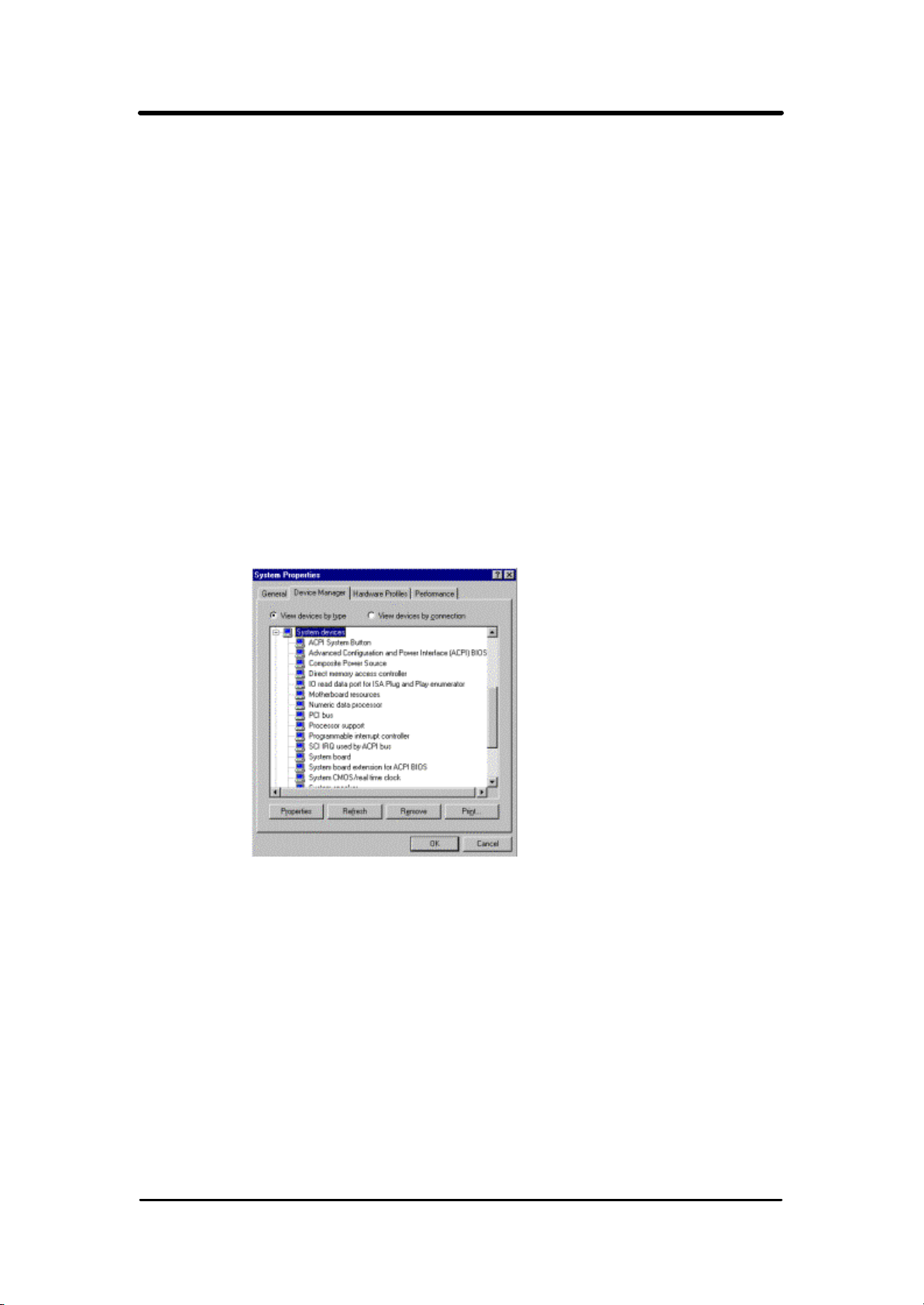
6. Boot Windows 98. In the Windows 98 desktop, click the Start
button. Move the cursor to Setting, then click Control Panel. To check
whether ACPI was properly installed, double-click the System icon. In
the System Properties dialog box, click the "Device Manager" tab. In
"View devices by type ", click "System devices".
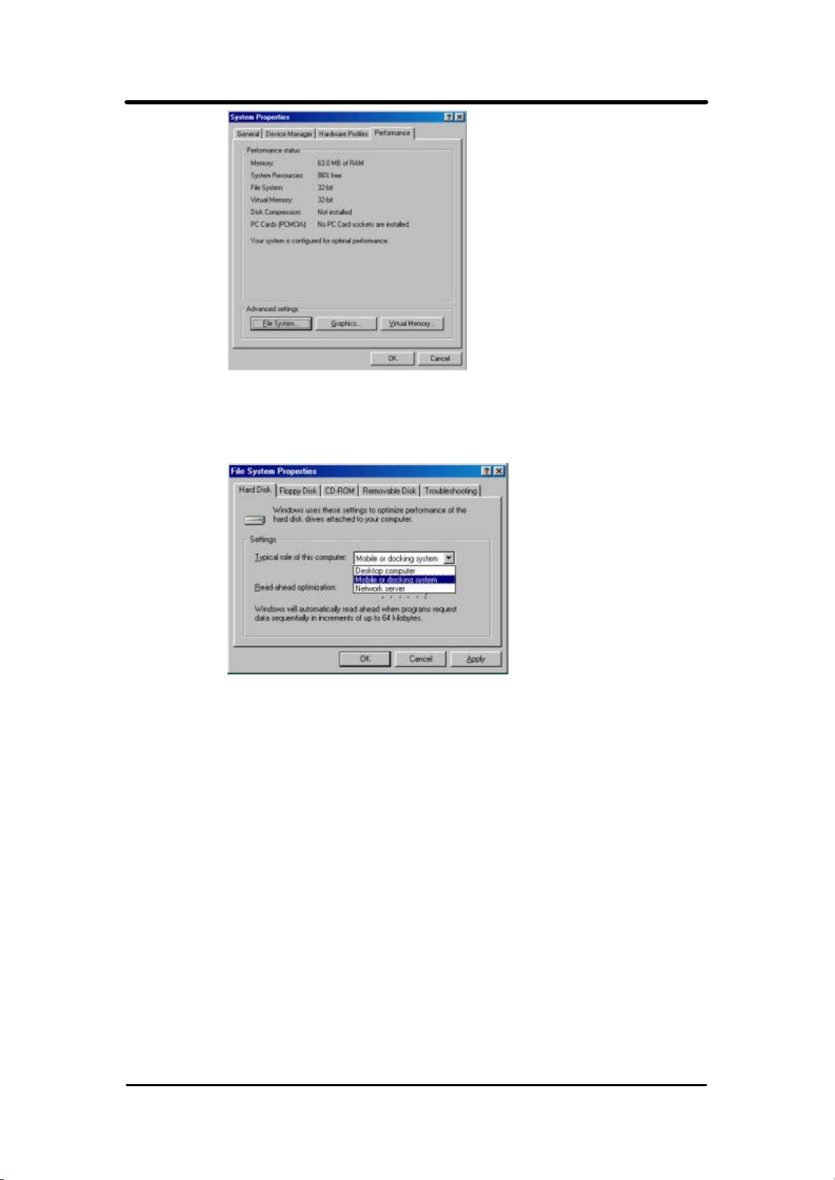
8.Double-click the System icon. In the System Properties dialog box,
click the Performance tab.
50
Page 51
P4VMA User’s Manual
9.Click File System. In the "Typical role of this computer" field,
select "Mobile or docking system". Click Apply, then click OK.
Restart the computer.
10.Repeat step 7 to open the Control Panel dialog box. Double-click
the Power Management icon.
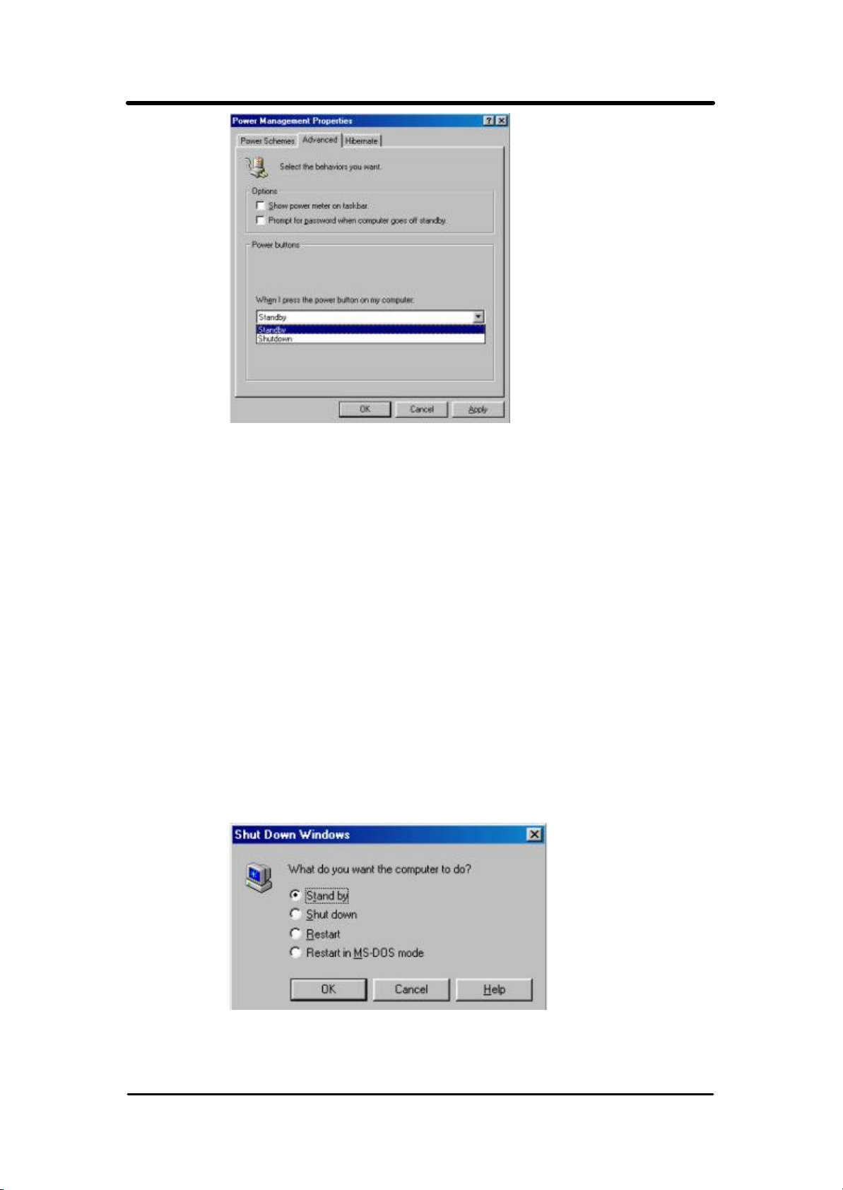
11.Click the Advanced tab. In the "When I press the power button
on my computer" field, select "Standby".
51
Page 52
P4VMA User’s Manual
After completing the steps above and you want to power-off the
computer, you do not need to go through the process of closing files,
applications and operation system. You can power off the computer at
once by pressing the power button or selecting "Standby" when you
shut down Windows 98.
To power-on the computer, just press the power button. The
operating session where you left off when you power-off the
computer will resume in not more than 8 seconds. However,
the power button will not function if a keyboard password has
been set in the "KB Power ON Password" field of the
Integrated Peripherals submenu. You must type the
password to power-on the computer.
If you have changed the color or resolution (in the Display
Properties dialog box), do not apply the settings without
restarting. You must restart the computer.
52
 Loading...