

Commell MS-C75 User Manual
MS-C75
Micro ATX Motherboard
User’s Manual
Edition 1.0
2012/11/22


MS-C75 User’s Manual
-1-
Copyright
Copyright 2012, all rights reserved. This document is copyrighted and all rights are
reserved. The information in this document is subject to change without prior notice to
make improvements to the products.
This document contains proprietary information and protected by copyright. No part of
this document may be reproduced, copied, or translated in any form or any means
without prior written permission of the manufacturer.
All trademarks and/or registered trademarks contains in this document are property of
their respective owners.
Disclaimer
The company shall not be liable for any incidental or consequential damages resulting
from the performance or use of this product.
The company does not issue a warranty of any kind, express or implied, including
without limitation implied warranties of merchantability or fitness for a particular purpose.
The company has the right to revise the manual or include changes in the specifications
of the product described within it at any time without notice and without obligation to
notify any person of such revision or changes.
Trademark
All trademarks are the property of their respective holders.
Any questions please visit our website at TUhttp://www.commell.com.twUT
MS-C75 User’s Manual
-2-
Packing List:
Please check the package contents before you starting using the board.
Hardware:
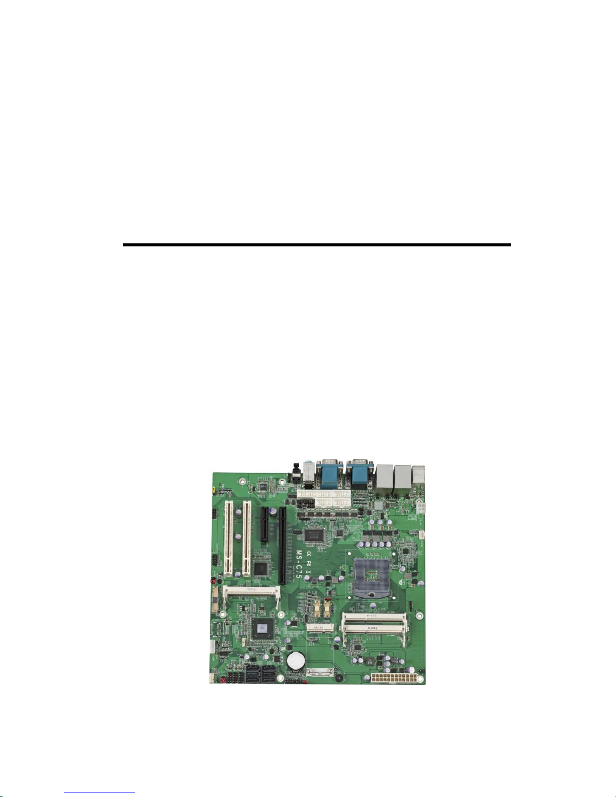
MS-C75 Micro ATX motherboard x 1
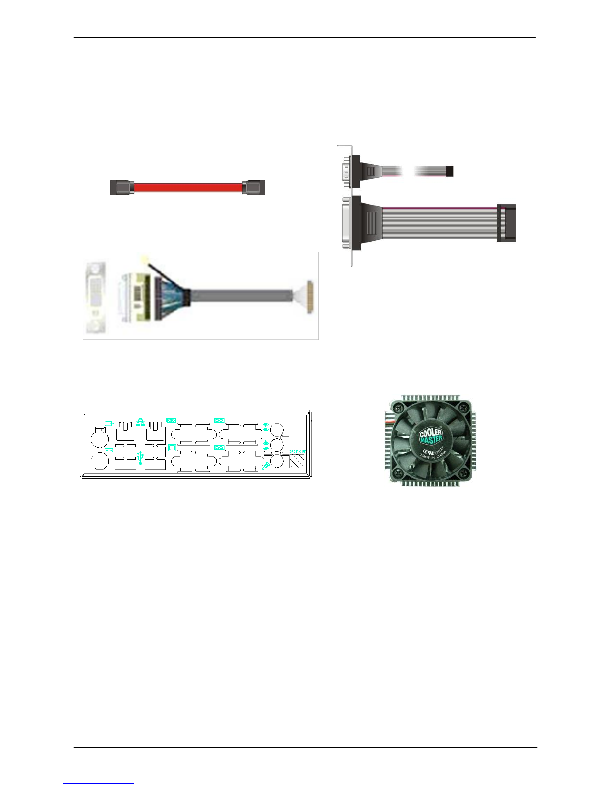
Cable Kit:
SATA Cable x 2
(OALSATA3-L)
I/O Shield x 1
(OALATE-LV67A)
Printed Matters:
Driver CD (Including User’s Manual) x 1
CPU Cooler x 1
(OHS-P-M-H)
DVI module with bracket x 1
(ADPDVIP & OALDVI-DF13)
DB25 & DB9 cable x 1
(OAL1S1P)

MS-C75 User’s Manual
-3-
Index
Chapter 1 <Introduction> .............................................................................. 6
1.1 <Product Overview> ..................................................................................... 6
1.2 <Product Specification> ................................................................................ 7
1.3 <Mechanical Drawing> ................................................................................. 8
1.4 <Block Diagram> .......................................................................................... 9
Chapter 2 <Hardware Setup> ...................................................................... 10
2.1 <Connector Location> ................................................................................ 10
2.2 <Jumper Location & Reference> ................................................................ 11
2.3 <Connector Reference> ............................................................................. 12
2.3.1 <Internal Connectors> ................................................................... 12
2.3.2 <External Connectors> .................................................................. 12
2.4 <CPU and Memory Setup> ........................................................................ 13
2.4.1 <CPU Setup> ................................................................................. 13
2.4.2 <Memory Setup> ........................................................................... 14
2.5 <CMOS & ATX Setup> ............................................................................... 15
2.6 <Serial ATA Interface> ................................................................................ 16
2.7 <Ethernet Interface> ................................................................................... 16
2.8 <Onboard Display Interface> ..................................................................... 17
2.8.1 <Analog Display> ........................................................................... 17
2.8.2 <Digital Display> ............................................................................ 18
2.8.3 <DVI Interface> .............................................................................. 22
2.9 <Integrated Audio Interface> ...................................................................... 23
2.10 <USB Interface> ....................................................................................... 25
2.11 <Serial Port> ............................................................................................. 27
2.12 <PCIE Mini Card and SIM Interface> ....................................................... 30
2.13 <GPIO and SMBUS Interface> ................................................................. 31
2.14 <Power Supply and Fan Interface > ......................................................... 32
2.14.1 <Power Input> ............................................................................. 32

MS-C75 User’s Manual
-4-
2.15 <Switch and Indicator> ............................................................................. 33
Chapter 3 <System Setup> ......................................................................... 34
3.1 <Audio Configuration> ................................................................................ 34
3.2 <Display Properties Setting> ...................................................................... 35
Chapter 4 <BIOS Setup> ............................................................................. 37
Appendix A <I/O Port Pin Assignment> ..................................................... 39
A.1 <Serial ATA Port> ....................................................................................... 39
A.2 <IrDA Port>................................................................................................. 39
A.3 <VGA Port> ................................................................................................ 39
A.4 <LAN Port>................................................................................................. 39
A.5 <LAN LED Port> ......................................................................................... 40
A.6 <Parallel Port> ............................................................................................ 40
Appendix B <Flash BIOS> ........................................................................... 41
B.1 <Flash Tool> ............................................................................................... 41
B.2 <Flash BIOS Procedure> ........................................................................... 41
Appendix C <Programming GPIO’s> ......................................................... 42
Appendix D <Programming Watchdog Timer > ........................................ 43
Contact Information ..................................................................................... 44

MS-C75 User’s Manual
-5-
(This page is left for blank)

MS-C75 User’s Manual
-6-
Chapter 1 <Introduction>
1.1 <Product Overview>
MS-C75 the 3rd Generation Intel of Micro ATX motherboard, supports 3rd Generation
Intel® Core™ i7, Core™ i5, Core™ i3 Mobile Processor and features Intel QM77
chipset, integrated HD Graphics, DDR3 memory, REALTEK High Definition Audio, Serial
ATA and Intel Gigabit LAN.
Intel Ivy Bridge Processor
The 3
rd
Generation Intel® Core™ processor family mobile is the next generation of
64-bit, multi-core mobile processor built on 22- nanometer process technology.
Based on a new micro-architecture.
New features for Intel QM77 chipset
The board integrates Intel QM77 chipset, supports integrated HD Graphics, built-in high
speed mass storage interface of serial ATA, High Definition Audio with 2 channels
surrounding sound.
All in One multimedia solution
Based on Intel QM77 chipset, the board provides high performance onboard graphics,
24-bit dual channel LVDS interface, DVI and 2 channels High Definition Audio, to meet
the very requirement of the multimedia application.
Flexible Extension Interface
The board provides, one Mini-PCIe sockets, one PCIe x16/x4 slot, one Mini PCI and two
PCI slots.

MS-C75 User’s Manual
-7-
1.2 <Product Specification>
General Specification
Form Factor
Micro ATX motherboard
CPU
3rd Generation Intel® Core™ i7, Core™ i5, Core™ i3 Mobile Processor
Package type: rPGA988B
Memory
2 x DDRIII SO-DIMM 1066/1333/1600 MHz up to 16GB
Chipset
Intel QM77 Express chipset
Real Time Clock
Chipset integrated RTC with onboard lithium battery
Watchdog Timer
Generates a system reset with internal timer for 1min/s ~255min/s
Power Management
Supports ACPI 3.0 compliant,
Serial ATA Interface
4 x serial ATAII interface with 300MB/s transfer rate
2 x serial ATAIII interface with 600MB/s transfer rate
VGA Interface
Onboard DSUB15 connector for VGA interface
LVDS Interface
Onboard 24-bit dual channel LVDS connector with +3.3V/+5V/+12V
supply
DVI Interface
Onboard DVI 20-pin connector
Audio Interface
Realtek ALC888 HD Audio
LAN Interface
1 x Intel 82579LM Gigabit LAN
1 x Intel 82574L Gigabit LAN
GPIO interface
Onboard programmable 8-bit Digital I/O interface
Extended Interface
1 x PCIe x16/x4 slot, 1 x PCIe mini card socket, 2 x PCI, 1 x Mini PCI
(Optional support mSATA(SATAII) for Mini_Card1,but SATA6 will be
disable)
Internal I/O Port
3 x RS232,1 x SMBUS, 1 x GPIO, 6 x USB2.0 ports, 1 x IrDA, 1 x DVI ,
1 x LVDS, 4 x Serial ATAII,2 x Serial ATAIII, 1 x Front panel Audio
and 1 x CDIN
External I/O Port
1 x PS/2, 2 x LAN ports, 1 x VGA port, 4 x USB3.0 ports,
1 x RS232/422/485, 2 x RS232, 1 x SPDIF and 1 x 2 Channel Audio
Power Requirement
Standard 24-pin ATX power supply (20-pin is compatible)
and P4 4-pin 12V
Dimension
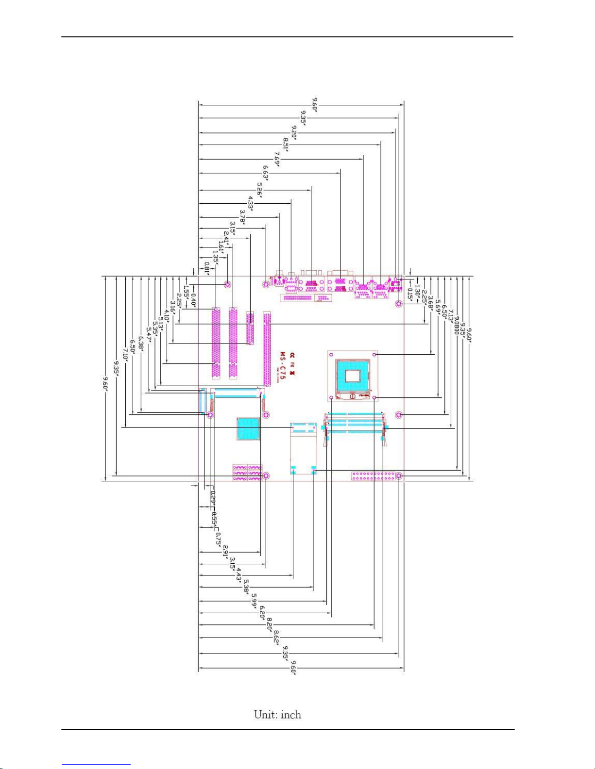
244mm x 244mm
Temperature
Operating within 0~60 centigrade
Storage within –20~85 centigrade
Ordering Code
MS-C75TXD
Intel PGA988B+ QM77 Onboard VGA, LVDS, DVI, LAN, USB2.0,
USB3.0, HD Audio, SATAII, SATAIII, SMBUS, LPC, SIM, GPIO,
PCIE x16, PCI and Mini PCI, PCI Express mini card
MS-C75TXDS
Intel PGA988B+ QM77 Onboard VGA, LVDS, DVI, LAN, USB2.0,
USB3.0, HD Audio, SATAII, SATAIII, SMBUS, LPC, SIM, GPIO,
PCIE x16, PCI and Mini PCI, mSATA
All product specifications are subject to change without notice.
For further product information please visit the website at TUhttp://www.commell.com.twUT
MS-C75 User’s Manual
-8-
1.3 <Mechanical Drawing>
MS-C75 User’s Manual
-9-
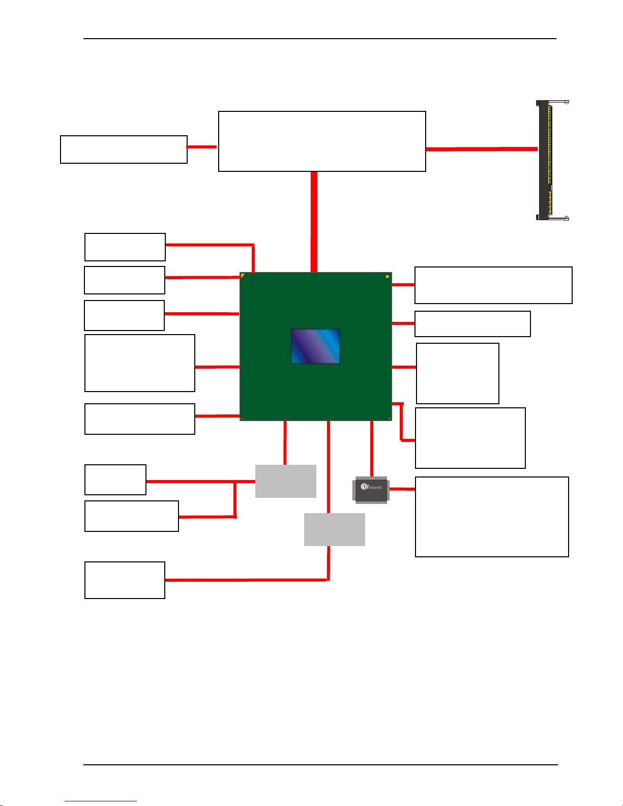
1.4 <Block Diagram>
QM77
1 x Intel 82579LM
1 x Intel 82574L
1 x RS232/422/485
1 x RS232 & GPIO & IrDA
1 x LPT
3rd Generation Intel® Core™ i7,
Core™ i5, Core™ i3
Mobile Processor
1 x PCI Express x16
2 x 204-pin DDR3
SO-DIMM
1066/1333/1600 MHz
up to 16GB
1 x LVDS
4 x Serial ATAII
2 x Serial ATAIII
6 x USB 2.0
4 x USB 3.0
1 x PCI Express mini card
1 x DVI
1 x CRT
4 x RS232
ALC888 HD
F81216
1 x PCI Express x4
2 x PCI
1 x Mini PCI
SI383
MS-C75 User’s Manual
-10-
Chapter 2 <Hardware Setup>
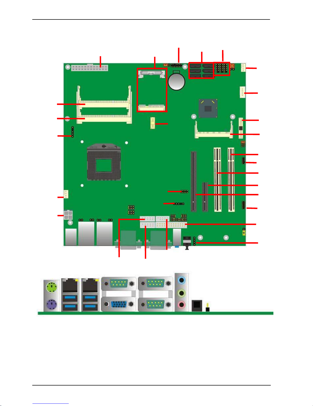
2.1 <Connector Location>
PS2
COM3+COM2 Audio SPDIF
COM1 + CRT
USB_RJ45_1/2
MINI_CARD1
SO_DIMM1
SO_DIMM2
ATX
1 / 4
2 / 5
3 / 6
SATA
CN_INV
CN_LVDS
MINIPCI
PCI2
PCI1
CN_AUDIO
SYSFAN
PCIE_4X
PCIE_16X
CN_DIO
CD_IN
CN_IR
CN_LPC
CN_DVI
CN_SMBUS
CPUFAN
CN_12V
CN_LPT
CN_COM6
CN_COM5
CN_COM4
CN_USB 2/1/5
JFRNT
MS-C75 User’s Manual
-11-
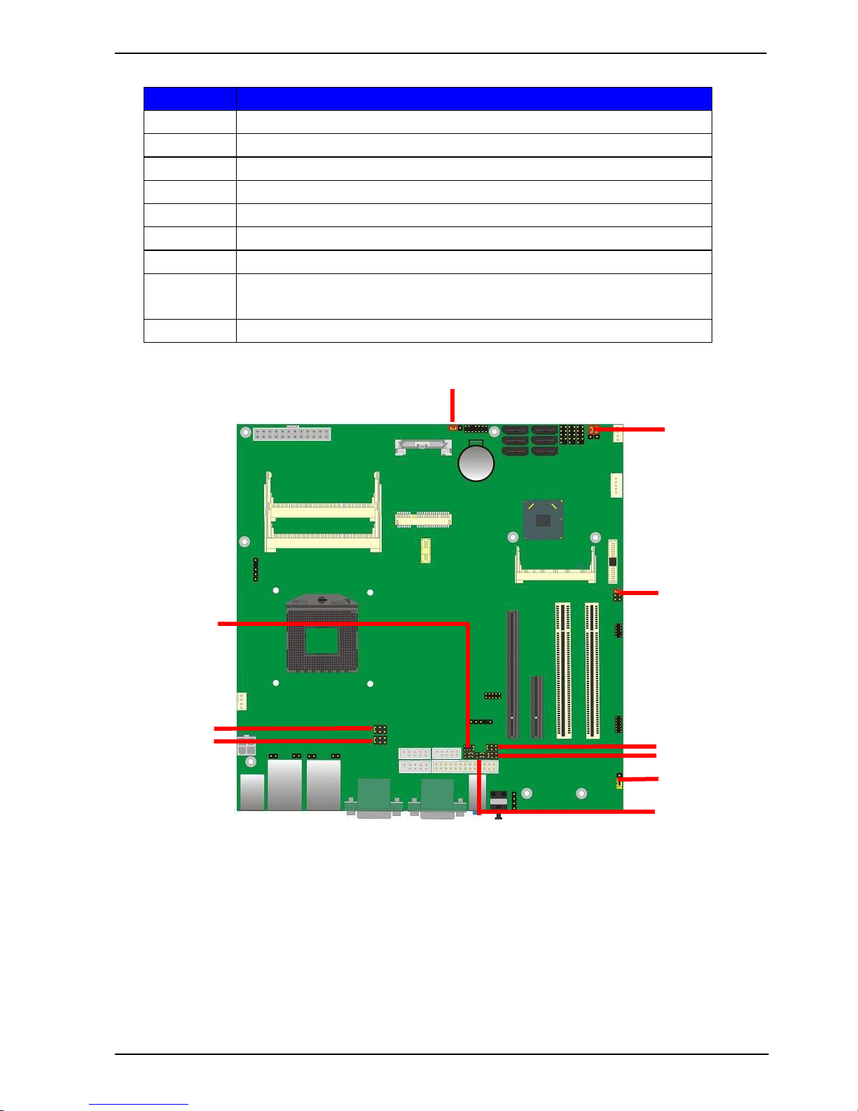
2.2 <Jumper Location & Reference>
Jumper
Function
JRTC
CMOS Operating/Clear Setting
JVLCD
Panel Voltage Setting
JAT
Power mode select
JP1
COM1 Voltage Setting (For Pin 9)
JP2
COM2 Voltage Setting (For Pin 9)
JP3
COM3 Voltage Setting (For Pin 9)
JP4
COM4 Voltage Setting (For Pin 9)
JCSEL1
JCSEL2
CN_COM2 RS-232 RS422 RS485 Setting
CN_IR IrDA Setting
JVUSB
USB Voltage Setting
JVLCD
JRTC
JP2
JVUSB
JP4
JP3
JP1
JCSEL2
JCSEL1
JAT
MS-C75 User’s Manual
-12-
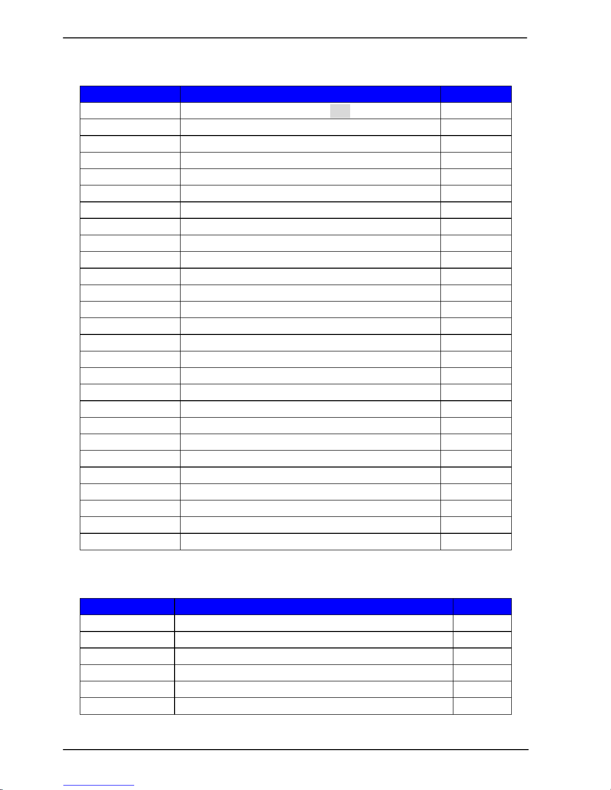
2.3 <Connector Reference>
2.3.1 <Internal Connectors>
Connector
Function
Remark
CPU
Socket rPGA988B for PGA988 CPU
SO-DIMM 1/2
204 -pin DDR3 SO-DIMM socket
SATA 1/2
7-pin Serial ATAIII connector
SATA 3/4/5/6
7-pin Serial ATAII connector
CN_12V
4-pin +12v additional power supply connector
ATX
24-pin power input connector
CN_AUDIO
5 x 2-pin audio connector
CD_IN
4-pin CD-ROM audio input connector
CN_DIO
6 x 2-pin digital I/O connector
CN_USB 1/2/5
5 x 2-pin USB connector
CPUFAN
4-pin CPU cooler fan connector
SYSFAN
4-pin system cooler fan connector
CN_LVDS
20 x 2-pin LVDS connector
CN_INV
5-pin LCD inverter connector
CN_IR
5-pin IrDA connector
CN_COM 4/5/6
9-pin RS232
CN_LPC
5 x 2-pin LPC connector
JFRNT
14-pin front panel switch/indicator connector
PCIE_16X
164-pin x16 PCIE slot
PCIE_4X
64-pin x4 PCIE slot
Mini-PCIE1
2 x 52-pin Mini-PCIE socket
PCI
120-pin PCI slot
MiniPCI
124-pin MiniPCI slot
JAT
Power mode select
JSPD 1/2
LAN Speed LED connector
JACT 1/2
LAN Activity LED connector
CN_LPT
13 x 2 printer connector
2.3.2 <External Connectors>
Connector
Function
Remark
USB_RJ45 1/2
2 x USB3.0 and 1 x RJ45 LAN connector
COM1 + CRT
COM1 Connect DB15 and analog VGA connector
COM 2/3
Serial port connector
PS/2
PS/2 keyboard and mouse connector
AUDIO
Audio connector
SPDIF
SPDIF digital audio output connector
 Loading...