

Page 1

MPX-24794S User’s Guide Ver 1.10
MPX-24794S Serial USB Card
SPI Master, I2C Master, Counter, GPIO through USB Interfaces
User’s Guide
Version 1.10
Taiwan Commate Computer Inc.
1
Page 2

MPX-24794S User’s Guide Ver 1.10
. Please check our Web site for the latest
© Taiwan Commate Computer Inc. 2012, 2013
TCC reserves the right to change the content without notify
version of this documentation.
19F, No 94, Sec 1, Shintai 5th Road, Sijhih Dist.
New Taipei City 22102, Taiwan
Tel: +886-2-2696-3909
FAX: +886-2-2696-3911
email: tech@commell.com.tw
www: www.commell.com.tw
www.commell.com
Taiwan Commate Computer Inc.
2
Page 3

MPX-24794S User’s Guide Ver 1.10
Contents
1 Introduction................................................................................................................. 2
1.1 Features............................................................................................................... 3
1.1.1 Hardware..................................................................................................... 3
1.1.2 Firmware..................................................................................................... 3
1.1.3 Software...................................................................................................... 4
1.2 Block Diagram.................................................................................................... 4
2 Hardware..................................................................................................................... 6
2.1 Card..................................................................................................................... 6
2.1.1 Connectors and Pins Definition.................................................................. 6
2.2 Cables.................................................................................................................. 9
2.2.1 OAL-24794S-CN1.................................................................................... 12
2.2.2 OAL-24794S-CN2.................................................................................... 14
2.2.3 OALUSB-H4-1 cable (option).................................................................. 15
2.2.4 OALUSB-H4 cable (option)..................................................................... 16
2.2.5 OAL-24794S-ADP Cable (option)........................................................... 16
2.3 Connecting to The PC....................................................................................... 19
2.3.1 Via Mini-PCIe Slot................................................................................... 19
2.3.2 Via OALUSB-H4-1 Cable (Option)......................................................... 20
2.3.3 Via OALUSB-H4 Cable (Option) ............................................................ 21
2.4 Optional GPIO Signal Isolation Boards............................................................ 22
2.4.1 ADP-GPION4I4O5V (option).................................................................. 22
2.4.2 ADP-GPION8I5V (option)....................................................................... 23
3 Device Drivers.......................................................................................................... 24
3.1 Device Drivers Installation............................................................................... 24
3.1.1 Windows 2000.......................................................................................... 25
3.1.2 Windows XP............................................................................................. 25
3.1.3 Windows Vista.......................................................................................... 26
3.1.4 Windows 7................................................................................................ 26
3.1.5 General Procedures................................................................................... 26
4 References................................................................................................................. 34
Taiwan Commate Computer Inc.
3
Page 4

MPX-24794S User’s Guide Ver 1.10
Lists of Figures
Figure 1 MPX-24794S USB-Serial Card............................................................................ 2
Figure 2 Block Diagram...................................................................................................... 5
Figure 3 MPX-24794S Serial USB Card............................................................................ 6
Figure 4 MPX-24794S Connectors..................................................................................... 7
Figure 5 OAL-24794S-CN1 photo ................................................................................... 10
Figure 6 OAL-24794S-CN2 photo ................................................................................... 11
Figure 7 OAL-24794S-ADP photo................................................................................... 12
Figure 8 OAL-24794S-CN1 Cable................................................................................... 13
Figure 9 OAL-24794S-CN2 Cable................................................................................... 14
Figure 10 OALUSB-H4-1 cable....................................................................................... 15
Figure 11 OALUSB-H4 cable .......................................................................................... 16
Figure 12 OAL-24794S-ADP cable.................................................................................. 17
Figure 13 Inserting to a standard Mini-PCIe slot.............................................................. 20
Figure 14 How to use OALUSB-H4-1 cable.................................................................... 21
Figure 15 How to use OALUSB-H4 cable ....................................................................... 22
Figure 16 ADP-GPION4I4O5V ....................................................................................... 23
Figure 17 ADP-GPION8I5V ............................................................................................ 23
Figure 18 Device Driver files Organization...................................................................... 25
Figure 19 MPX-24794S vs. Device Manager................................................................... 32
Figure 20 MPX-24794S Property Dialog......................................................................... 33
List of Tables
Table 1 CN_GPIO1 Pin Definitions................................................................................... 8
Table 2 CN_GPIO2 Pin Definitions................................................................................... 8
Table 3 J1 Connector pin-out definitions............................................................................ 8
Table 4 USB signals related to full-mini PCIe card ........................................................... 9
Table 5 CN_USB Pin Out Definitions................................................................................ 9
Table 6 OAL-24794S-CN1 cable mapping ...................................................................... 14
Table 7 OAL-24794S-CN2 cable mapping ...................................................................... 15
Table 8 P1 (2x6 header) mapping..................................................................................... 17
Table 9 P2 (2x6 header) mapping..................................................................................... 18
Table 10 All other pins mapping ...................................................................................... 18
Taiwan Commate Computer Inc.
4
Page 5
MPX-24794S User’s Guide Ver 1.10
Conventions
The numbers used in this manual.
Number Description
Decimal Decimal number will be noted just as normal numbers.
For example, 3456.
Hexadecimal Hexadecimal number will be noted in C-notation, the 0x prefix will be
presented.
For example, 0x3456.
Signs used in this manual.
Sign Description
Permanent damage. This sign indicates that permanent damage to the
device and system might cause if not fully understood or followed. You
should not start using the product before you have read this information.
Information sign. This sign indicates that this information might be
useful while you are using this product. This information might also help
saving your time if you have read them.
Taiwan Commate Computer Inc.
1
Page 6

MPX-24794S User’s Guide Ver 1.10
Acronyms and Abbreviations
API Application Programming Interface
AT24 Atmel AT24Cxxx I2C EEPROM
AT25 Atmel AT25xxx SPI EEPROM
CCP Common Communication Protocol
CNTR Counter
CNTR_EN Counter Enable input pin
CNTR_CO Counter Compare True output pin
CNTR_TO Counter Terminal Count output pin
CSn# Chip Select
EEPROM Electrically Erasable Programmable Read-Only Memory
GPIO General Purpose Input/Output
I2C Bus Inter-Integrated Circuit Bus
I2CM I2C Master
I2CmSCL I2C master clock
I2CmSDA I2C master data
LSB Least Significant Byte
MHz Megahertz (one million hertz)
MISO Master In Slave Out
MOSI Master Out Slave In
MSB Most Significant Byte
PCIe PCI Express
PWM Pulse Width Module
SCLK SPI Clock
SDK Software Development Kit
SPI Bus Serial Peripheral Interface Bus
SPIM SPI Master
USB Universal Serial Bus
Taiwan Commate Computer Inc.
1
Page 7
MPX-24794S User’s Guide Ver 1.10
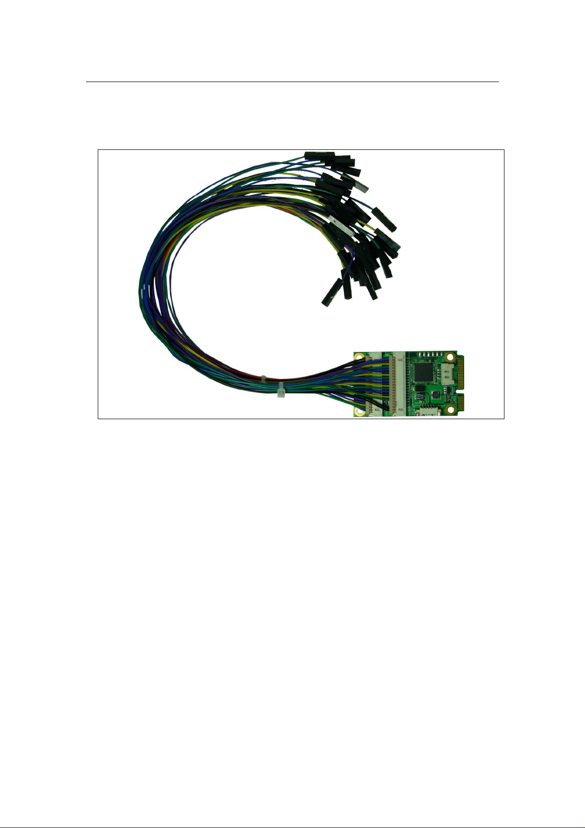
1 Introduction
Figure 1 MPX-24794S USB-Serial Card
MPX-24794S Serial USB Card provides SPI master interface, I2C master interface, a
16-bit general purpose counter, and 16-bit GPIO interfaces via USB 2.0 full speed
device connection. This card is in Mini-PCIe form factor and is using only the USB
signaling portion of the standard Mini-PCIe interface.
This card is powered by a Cypress CY8C24794 micro-controller with 24 MHz system
clock frequency. The USB is compliant to USB 2.0 full speed device. This card
provides you a convenience way to connect your systems to those SPI slave devices,
I2C slave devices, and devices that need GPIO interface. A 16-bit general counter
with Enable pin input is also provided. A compare true pin out and terminal count pin
out are also provided.
2.54mm pitch test pins are come with this card for your easy usage.
Device drivers for Microsoft Windows 2000, Windows XP (32-bit and 64-bit),
Windows Vista (32-bit and 64-bit), and Windows 7 (32-bit and 64-bit) are supplied in
the product CD.
Taiwan Commate Computer Inc.
2
Page 8

MPX-24794S User’s Guide Ver 1.10
The MPX-24749S firmware provides APIs for SPI master functions, I2C master
functions, 16-bit counter functions, and GPIO functions to be used by the USB host
side applications. USB host side applications communicate with MPX-24794S
firmware via USB Bulk In and Bulk Out transactions. The Common Communication
Protocol (CCP) is formatted within Bulk In and Bulk Out data. Please refer to the
MPX-24794S Programmer's Guide for detail technical information.
1.1 Features
1.1.1 Hardware
The MPX-24794S Serial USB Card is based on Cypress CY8C24794-24LTXI
System-on-Chip controller, which has the following features:
• M8C processor speeds up to 24 MHz
• Low power at high speed
•
USB 2.0 compliant at full speed (12 Mbps)
•
SPI Master module on Port 0
• SPI Master mode 0, 1, 2, 3 with 1 MHz clock frequency
• Selectable SPI setup time and hold time
•
Connects up to five SPI slave devices (CS0#, CS1#, CS2#, CS3#, CS4#)
•
Programmable 16-bit general purpose counter
• 16-bit Counter at 1 MHz clock rate
•
16-bit Counter with enable input pin
•
16-bit Counter with compare_true and terminal_count output pins
•
I2C Master supports standard mode of 100 kbps date rate
• 8-bit I2C slave address with Read/Write bit on bit-0
•
Programmable 16-bit GPIOs
•
8-bit GPIO on Port 3
•
8-bit GPIO on Port 4
• 25-mA sink, 10-mA source on all GPIOs
•
Pull-up, pull-down, high Z, strong, or open-drain drive modes on all GPIOs
•
Configurable interrupt on all GPIOs
1.1.2 Firmware
The MPX-24794S firmware supports the following features. Please refer to the MPX24794S Programmer Reference for details.
•
Optimized to run accurately and efficiently
• Bulk Out endpoint for commands sending
•
Bulk In endpoint for responses receiving
Taiwan Commate Computer Inc.
3
Page 9

MPX-24794S User’s Guide Ver 1.10
•
Interrupt In endpoint for checking certain status
•
Implement SPI master services
• Implement I2C master services
•
Implement 16-bit general purpose counter services
•
Implement 16-bit general purpose input/out services
1.1.3 Software
The MPX-24794S provides the following software features. Please refer to the MPX24794S Programmer’s Reference for details.
•
Devices drivers support Windows 2000, 32-/64-bit Windows XP, 32-/64-bit
Windows Vista, and 32-/64-bit Windows 7.
•
Cypress CyAPI.LIB library for C/C++ programming
•
Cypress CyUSB.NET class library, CyUSB.DLL, for Microsoft Windows
managed .NET programming. For example, Visual Basic, Visual C#, and
JScript.
•
Example Code in Microsoft Visual Studio 2010.
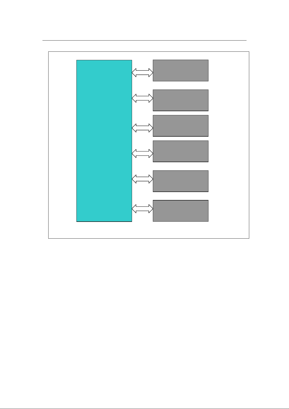
1.2 Block Diagram
The following Figure shows the block diagram of MPX24792S.
Taiwan Commate Computer Inc.
4
Page 10
MPX-24794S User’s Guide Ver 1.10
CY8C24794
USB 2.0 Full Speed
SPI Master
(Port 0)
I2C Master
(Port 2)
16-bit Counter
(Port 2)
8-bit GPIO
(Port 3)
8-bit GPIO
(Port 4)
Taiwan Commate Computer Inc.
Figure 2 Block Diagram
5
Page 11
MPX-24794S User’s Guide Ver 1.10
2 Hardware
This chapter depicts the MPX-24794S Serial USB Card in hardware point of view.
These cover the following topics:
•
Card
• Cables
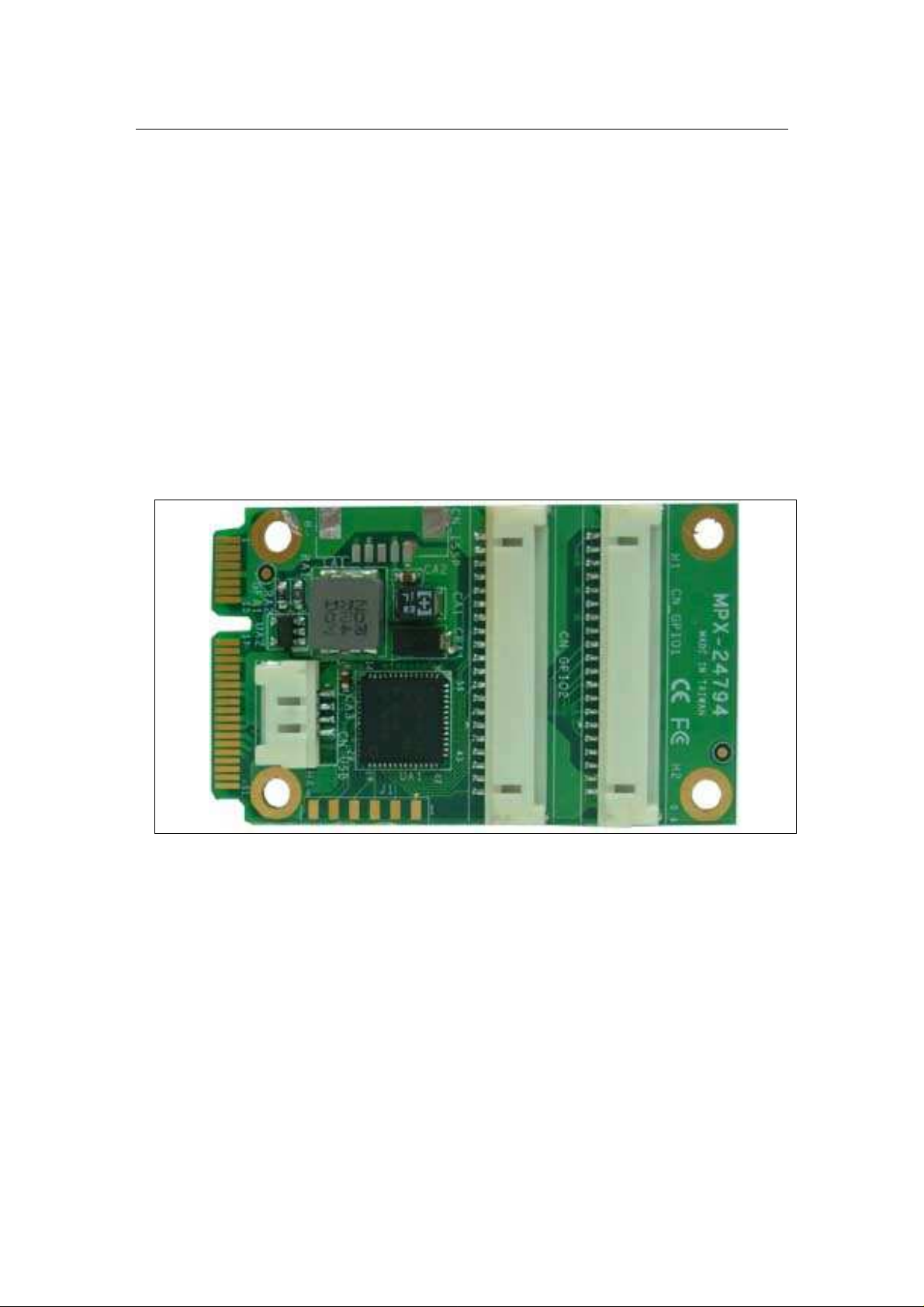
2.1 Card
The Cypress CY8C24794-24LXTI micro controller is the major component of the
MPX-24794S Serial USB Card. This CY8C24794 is located at the UA1 position.
Figure 3 MPX-24794S Serial USB Card
2.1.1 Connectors and Pins Definition
The following figure shows the connectors on the MPX-24794S card.
Taiwan Commate Computer Inc.
6
Page 12
MPX-24794S User’s Guide Ver 1.10
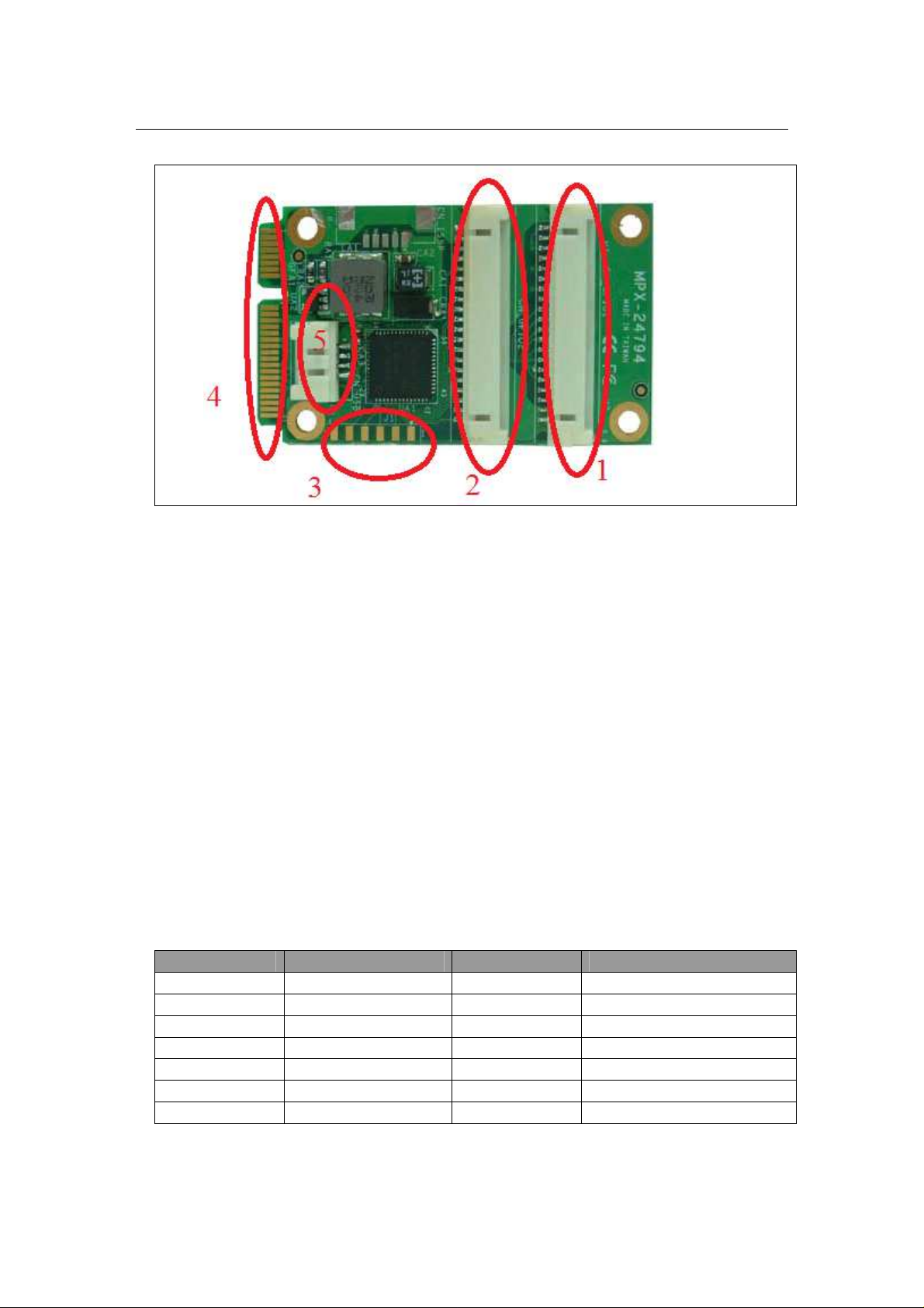
Figure 4 MPX-24794S Connectors
These five connectors are:
1. CN_GPIO1 – The connector that contains SPI master signals and SPI slaves
chip select signals, I2C master SCL and SDA signals, as well as Counter
signals.
2. CN_GPIO2 – All GPIO signals.
3. JP1 - Firmware update signals and others.
4. Mini-PCIe USB only signals – Plus this board into a Mini-PCIe slot will
connect to a USB port of your motherboard.
5. CN_USB – An alternate way to connect to a USB port of your motherboard
via connect OALUSB-H4-1 cable to this connector and its type A plug-in
connector.
The following table shows the pin-out definitions of the CN_GPIO1 connector.
PIN Description PIN Description
CN_GPIO1_1 GND CN_GPIO1_11 CS3#
CN_GPIO1_2 GND CN_GPIO1_12 CS4#
CN_GPIO1_3 PWR+5V CN_GPIO1_13 CNTR_EN
CN_GPIO1_4 PWR+5V CN_GPIO1_14 CNTR_CO
CN_GPIO1_5 MOSI CN_GPIO1_15 Reserved
CN_GPIO1_6 MISO CN_GPIO1_16 CNTR_TO
CN_GPIO1_7 SCLK CN_GPIO1_17 Reserved
Taiwan Commate Computer Inc.
7
Page 13

MPX-24794S User’s Guide Ver 1.10
CN_GPIO1_8 CS0# CN_GPIO1_18 I2CmSDA (4.7 K Ohm)
CN_GPIO1_9 CS1# CN_GPIO1_19 Reserved
CN_GPIO1_10 CS2# CN_GPIO1_20 I2CmSCL (4.7 K Ohm)
Table 1 CN_GPIO1 Pin Definitions
Note:
A pull-up 4.7 K Ohm resistor is installed on I2CmSDA line and I2CmSCL line
respectively.
The following table shows the pin-out definitions of the CN_GPIO2 connector.
PIN Description PIN Description
CN_GPIO2_1 Port_3_0 CN_GPIO2_11 Port_4_2
CN_GPIO2_2 Port_3_1 CN_GPIO2_12 Port_4_3
CN_GPIO2_3 Port_3_2 CN_GPIO2_13 Port_4_4
CN_GPIO2_4 Port_3_3 CN_GPIO2_14 Port_4_5
CN_GPIO2_5 Port_3_4 CN_GPIO2_15 Port_4_6
CN_GPIO2_6 Port_3_5 CN_GPIO2_16 Port_4_7
CN_GPIO2_7 Port_3_6 CN_GPIO2_17 N/C
CN_GPIO2_8 Port_3_7 CN_GPIO2_18 N/C
CN_GPIO2_9 Port_4_0 CN_GPIO2_19 GND
CN_GPIO2_10 Port_4_1 CN_GPIO2_20 GND
Table 2 CN_GPIO2 Pin Definitions
The following table shows the pin-out definitions of the JP1 connector.
PIN Description
J1_1 Reserved
J1_2 Reserved
J1_3 Reserved
J1_4 Reserved
J1_5 Reserved
J1_6 Enter firmware update mode via grounding this pin
Table 3 J1 Connector pin-out definitions
The following table shows the USB portion pin-outs of the Mini-PCIe interface.
Please be noted that power pins are not showed.
Pin Name Description
Taiwan Commate Computer Inc.
8
Page 14

MPX-24794S User’s Guide Ver 1.10
38 USB_D+ Related to full-mini PCIe card
37 GND Related to full-mini PCIe card
36 USB_D- Related to full-mini PCIe card
35 GND Related to full-mini PCIe card
Table 4 USB signals related to full-mini PCIe card
The following table shows the pin-out definitions of the CN_USB connector.
Pin Name Description
1 +5V Red color
2 USB_D- White color
3 USB_D+ Green color
4 GND Black color
Table 5 CN_USB Pin Out Definitions
2.2 Cables
The following cables can be used with MPX-24794S card. Two of them are standard
cables that come with the product. Others are optional.
•
OAL-24794S-CN1 (standard)
•
OAL-24794S-CN2 (standard)
• OALUSB-H4-1 (option)
•
OAL-27494S-ADP (option)
Taiwan Commate Computer Inc.
9
Page 15

MPX-24794S User’s Guide Ver 1.10
10
Figure 5 OAL-24794S-CN1 photo
Taiwan Commate Computer Inc.
Page 16

MPX-24794S User’s Guide Ver 1.10
11
Figure 6 OAL-24794S-CN2 photo
Taiwan Commate Computer Inc.
Page 17

MPX-24794S User’s Guide Ver 1.10
12
Figure 7 OAL-24794S-ADP photo
2.2.1 OAL-24794S-CN1
This cable is used to connect to the CN_GPIO1 connector.
Taiwan Commate Computer Inc.
Page 18

MPX-24794S User’s Guide Ver 1.10
13
Figure 8 OAL-24794S-CN1 Cable
Item Description
1 28AWG
2 28AWG
3 HOUSING PITCH: 1.25mm
5 HOUSING PITCH: 2.54mm
Connects the P1 side of the OAL-24794S-CN1 to the CN_GPIO1 connector of the
MPX-24749S card.
The following table shows the mapping of this cable.
Pin Color P1 connector CN_GPIO1 connector
P2 Black P1_1 CN_GPIO1_1
P3 Black P1_2 CN_GPIO1_2
P4 Red P1_3 CN_GPIO1_3
P5 Red P1_4 CN_GPIO1_4
P6 Purple P1_5 CN_GPIO1_5
P7 Yellow P1_6 CN_GPIO1_6
P8 Green P1_7 CN_GPIO1_7
P9 Blue P1_8 CN_GPIO1_8
P10 Purple P1_9 CN_GPIO1_9
P11 Yellow P1_10 CN_GPIO1_10
P12 Green P1_11 CN_GPIO1_11
P13 Blue P1_12 CN_GPIO1_12
P14 Purple P1_13 CN_GPIO1_13
P15 Yellow P1_14 CN_GPIO1_14
P16 Green P1_15 CN_GPIO1_15
Taiwan Commate Computer Inc.
Page 19

MPX-24794S User’s Guide Ver 1.10
14
P17 Blue P1_16 CN_GPIO1_16
P18 Purple P1_17 CN_GPIO1_17
P19 Yellow P1_18 CN_GPIO1_18
P20 Blue P1_19 CN_GPIO1_19
P21 Green P1_20 CN_GPIO1_20
Table 6 OAL-24794S-CN1 cable mapping
Please refer to the Connectors and Pins section for CN_GPIO2 signals.
2.2.2 OAL-24794S-CN2
This cable is used to connect to the CN_GPIO2 connector.
Figure 9 OAL-24794S-CN2 Cable
Item Description
1 28AWG
2 28AWG
3 HOUSING PITCH: 1.25mm
5 HOUSING PITCH: 2.54mm
Connects the P1 side of the OAL-24794S-CN2 to the CN_GPIO2 connector of the
MPX-24794S card.
The following table shows the mapping of this cable.
Taiwan Commate Computer Inc.
Page 20

MPX-24794S User’s Guide Ver 1.10
15
Pin Color P1 Plug CN_GPIO2 connector
P2 Blue P1_1 CN_GPIO2_1
P3 Purple P1_2 CN_GPIO2_2
P4 Yellow P1_3 CN_GPIO2_3
P5 Green P1_4 CN_GPIO2_4
P6 Blue P1_5 CN_GPIO2_5
P7 Purple P1_6 CN_GPIO2_6
P8 Yellow P1_7 CN_GPIO2_7
P9 Green P1_8 CN_GPIO2_8
P10 Blue P1_9 CN_GPIO2_9
P11 Purple P1_10 CN_GPIO2_10
P12 Yellow P1_11 CN_GPIO2_11
P13 Green P1_12 CN_GPIO2_12
P14 Blue P1_13 CN_GPIO2_13
P15 Purple P1_14 CN_GPIO2_14
P16 Yellow P1_15 CN_GPIO2_15
P17 Green P1_16 CN_GPIO2_16
Blank Not Connected P1_17 CN_GPIO2_17
Blank Not Connected P1_18 CN_GPIO2_18
P18 Black P1_19 CN_GPIO2_19
P19 Black P1_20 CN_GPIO2_20
Table 7 OAL-24794S-CN2 cable mapping
Please refer to the Connectors and Pins section for the CN_GPIO2 signals.
2.2.3 OALUSB-H4-1 cable (option)
OALUSB-H4-1 cable is an alternate cable to connect the MPX-24794S card to one of
the USB 2.0 port on your motherboard. OALUSB-H4-1 is an USB 2.0 Type A plugin cable.
The following figure shows the cable description.
Figure 10 OALUSB-H4-1 cable
Taiwan Commate Computer Inc.
Page 21

MPX-24794S User’s Guide Ver 1.10
16
Connect the P2 to the CN_USB port of the MPX-24749S card. OALUSB-H4-1 cable
is convenient for your development stage.
2.2.4 OALUSB-H4 cable (option)
OALUSB-H4 cable is another alternate cable to connect the MPX-24794S card to one
of the USB 2.0 pin header on your motherboard.
The following figure shows the cable description.
Figure 11 OALUSB-H4 cable
Connecting the P2 to the CN_USB port of the MPX-24749S card meanwhile
connecting P1 to a USB 2.0 pin header of your target motherboard.
2.2.5 OAL-24794S-ADP Cable (option)
This cable is specific designed to connect MPX-24794S board to ADPGPION4I4O5V and ADP-GPION8I5V Commell GPIO signaling isolation boards.
This cable is optional to the MXP-24794S card. The following figure shows the
drawing of this cable.
Taiwan Commate Computer Inc.
Page 22

MPX-24794S User’s Guide Ver 1.10
17
Figure 12 OAL-24794S-ADP cable
Item Description
1,9,10 28AWG
2,3 HOUSING PITCH: 1.25mm
4,5 HOUSING PITCH: 2.54mm
6,7 HOUSING (2x6 headers) PITCH: 2.0mm
Connect P4 to the CN_GPIO1 connector of the MPX-24794S card. Connects P3 to
the CN_GPIO2 connector of the MPX-24794S card.
The following tables show the mapping of all pins of this cable.
P1 connector Color P3 connector CN_GPIO2 connector
P1_1 (GND) Black P3_19 CN_GPIO2_19
P1_2 (GND) Black P3_19 CN_GPIO2_19
P1_3 Blue P3_1 CN_GPIO2_1
P1_4 Blue P3_5 CN_GPIO2_5
P1_5 Yellow P3_2 CN_GPIO2_2
P1_6 Yellow P3_6 CN_GPIO2_6
P1_7 Purple P3_3 CN_GPIO2_3
P1_8 Purple P3_7 CN_GPIO2_7
P1_9 Green P3_4 CN_GPIO2_4
P1_10 Green P3_8 CN_GPIO2_8
P1_11 (+5V) Red P4_3 (PWR+5V) CN_GPIO1_3 (PWR+5V)
P1_12 N/C N/C N/C
Table 8 P1 (2x6 header) mapping
Taiwan Commate Computer Inc.
Page 23

MPX-24794S User’s Guide Ver 1.10
18
P2 connector Color P3 connector CN_GPIO2 connector
P2_1 (GND) Black P3_20 CN_GPIO2_20
P2_2 (GND) Black P3_20 CN_GPIO2_20
P2_3 Blue P3_9 CN_GPIO2_9
P2_4 Blue P3_13 CN_GPIO2_13
P2_5 Yellow P3_10 CN_GPIO2_10
P2_6 Yellow P3_14 CN_GPIO2_14
P2_7 Purple P3_11 CN_GPIO2_11
P2_8 Purple P3_15 CN_GPIO2_15
P2_9 Green P3_12 CN_GPIO2_12
P2_10 Green P3_16 CN_GPIO2_16
P2_11 (+5V) Red P4_4 (PWR+5V) CN_GPIO1_4 (PWR+5V)
P2_12 N/C N/C N/C
Table 9 P2 (2x6 header) mapping
Pin Color P4 connector CN_GPIO1 connector
P5 Blue P4_1 CN_GPIO1_1
P6 Yellow P4_2 CN_GPIO1_2
P7 Red P4_3 CN_GPIO1_3
P8 Red P4_4 CN_GPIO1_4
P9 Purple P4_5 CN_GPIO1_5
P10 Green P4_6 CN_GPIO1_6
P11 Blue P4_7 CN_GPIO1_7
P12 Yellow P4_8 CN_GPIO1_8
P13 Purple P4_9 CN_GPIO1_9
P14 Green P4_10 CN_GPIO1_10
P15 Blue P4_11 CN_GPIO1_11
P16 Yellow P4_12 CN_GPIO1_12
P17 Purple P4_13 CN_GPIO1_13
P18 Green P4_14 CN_GPIO1_14
P19 Blue P4_15 CN_GPIO1_15
P20 Yellow P4_16 CN_GPIO1_16
P21 Purple P4_17 CN_GPIO1_17
P22 Green P4_18 CN_GPIO1_18
P23 Blue P4_19 CN_GPIO1_19
P24 Yellow P4_20 CN_GPIO1_20
Table 10 All other pins mapping
Taiwan Commate Computer Inc.
Page 24

MPX-24794S User’s Guide Ver 1.10
19
2.3 Connecting to The PC
This section depicts how to connect the MPX-24794S card to a target platform,
specifically a Microsoft Windows based PC. There are three ways that a MPX24794S can be connecting to a PC but only one is allowed at a time.
•
Through Mini-PCIe slot
•
Through OALUSB-H4-1 cable
•
Through OALUSB-H4 cable
Use only one connecting method of the above three methods to
connect a MPX-24749S card to the target PC.
2.3.1 Via Mini-PCIe Slot
You can simply connect a MPX-24749S card to the target PC via inserting a MPX24749S card into a standard Mini-PCIe slot. This is because a standard Mini-PCIe
slot provides USB signals in its interface. Commell motherboards that feature MiniPCIe slot(s) are compliant to industrial standard Mini-PCIe slot interface and
therefore are good for MPX-24794S card. Please check your target board user's
manual.
The following figure shows how to insert a MPX-24749S card into a standard MiniPCIe slot of a motherboard.
Taiwan Commate Computer Inc.
Page 25

MPX-24794S User’s Guide Ver 1.10
20
Figure 13 Inserting to a standard Mini-PCIe slot
2.3.2 Via OALUSB-H4-1 Cable (Option)
Another way to connect MPX-24794S card to your target PC is via OALUSB-H4-1
cable. One end of this cable connecting to the MPX-24794S and the other end
connecting to a USB Type A receptacle of your target PC.
The following figure shows how to connect MPX-24749S card to your target PC via
OALUSB-H4-1 cable.
Taiwan Commate Computer Inc.
Page 26

MPX-24794S User’s Guide Ver 1.10
21
Figure 14 How to use OALUSB-H4-1 cable
2.3.3 Via OALUSB-H4 Cable (Option)
Third way to connect a MPX-24749S card to your target PC is via OALUSB-H4
cable. This cable connects a MPX-24794S card to the target PC through USB pin
header. Please check the user's manual of your motherboard to locate a right USB pin
header.
The following figure shows how the OALUSB-H4 cable is connecting a MPX24749S card to a target PC.
Taiwan Commate Computer Inc.
Page 27

MPX-24794S User’s Guide Ver 1.10
22
Figure 15 How to use OALUSB-H4 cable
2.4 Optional GPIO Signal Isolation Boards
In the real practical situations, cases are connecting signal isolation boards to MPX24794S cards before connecting to those input and /or output devices. Both ADPGPIO4I4O5V and ADP-GPION8I5V boards are designed for this purpose.
MPX-24794S card provides a convenient way to connect to the ADP-GPION4I4O5V
and ADP-GPION8I5V signal isolation boards. The OAL-24794S-ADP cable is
designed specially to connect to these two boards.
2.4.1 ADP-GPION4I4O5V (option)
ADP-GPION-4I4O5V is a signaling isolation board for Commell GPIO products.
This board has four photo-couple input connectors and four relay output connectors.
Four photo-couple diodes protect input lines from the damage caused by ElectroStatic
Discharge (ESD) and other transients. Four relays feature high current contacts
capability.
Taiwan Commate Computer Inc.
Page 28

MPX-24794S User’s Guide Ver 1.10
23
Figure 16 ADP-GPION4I4O5V
Use either P1 and/or P2 connector (2x6 header) of OAL-24794S-ADP cable to
connect to one or two of this board.
2.4.2 ADP-GPION8I5V (option)
ADP-GPION8I5V is a signaling isolation board for Commell GPIO products. This
board has eight photo-couple input connectors. Eight photo-couple diodes protect
input lines from the damage caused by ElectroStatic Discharge (ESD) and other
transients.
Figure 17 ADP-GPION8I5V
Use either P1 and/or P2 connector (2x6 header) of OAL-24794S-ADP cable to
connect to one or two of this board.
Taiwan Commate Computer Inc.
Page 29

MPX-24794S User’s Guide Ver 1.10
24
3 Device Drivers
This chapter describes how to install the MPX-24794S Serial USB Card device
drivers. A successful device driver installation is mandatory in order to make MPX24794S card working properly.
MPX-24794S Card supports the following operating systems.
•
Windows 2000 – Device driver files located in w2k\x86 folder.
•
Windows XP 32-/64-bit versions – Device driver files located in wxp\x86 and
wxp\x64 folder respectively.
• Windows Vista 32-/64-bit versions – Device driver files located in wlh\x86
and wlh\x64 folder respectively.
•
Windows 7 32-/64-bit versions – Device driver files located in wlh\x86 and
wlh\x64 folder respectively.
3.1 Device Drivers Installation
This section describes how to install the corresponding device driver to your target
Windows operating systems.
The following figure shows the device driver files organization.
Taiwan Commate Computer Inc.
Page 30

MPX-24794S User’s Guide Ver 1.10
25
Figure 18 Device Driver files Organization
3.1.1 Windows 2000
MPX-24794S card device driver for Windows 2000 is supported. Follow these
instructions to install the corresponding device driver for your operating system.
Direct your device driver installation wizard to the .\w2k\x86 folder for the right
device driver for Windows 2000.
3.1.2 Windows XP
MPX-24794S card device drivers for Windows XP 32-/64-bit versions are supported.
Follow these instructions to install the corresponding device driver for your operating
system.
Direct your device driver installation wizard to the .\wxp\x86 if you are using the 32bit Windows XP system; while the .\wxp\x64 contains the device driver for your 64bit Windows XP system.
Taiwan Commate Computer Inc.
Page 31

MPX-24794S User’s Guide Ver 1.10
26
3.1.3 Windows Vista
MPX-24794S card device drivers for Windows Vista 32-/64-bit versions are
supported. Follow these instructions to install the corresponding device driver for
your operating system.
Direct the installation wizard to the .\wlh\x32 for your 32-bit Windows Vista system.
The .wlh\x64 contains the driver for your 64-bit Windows Vista system.
3.1.4 Windows 7
MPX-24794S card device drivers for Windows 7 32-/64-bit versions are supported.
Follow these instructions to install the corresponding device driver for your operating
system.
Direct the installation wizard to the .\wlh\x32 for your 32-bit Windows 7 system.
Meanwhile, the .\wlh\x64 folder contain the device driver for your 64-bit Windows 7
system.
3.1.5 General Procedures
This section describes the general procedures while you are installing device driver
for MPX-24794S Card on Microsoft Windows XP system. The procedures here are
common and/or similar to all Microsoft Windows Systems.
1. Insert the MPX-24794S card companion CD into the target system or copy its
device driver folder to the target system.
2. Insert the MPX-24794S card into the system and then follow the Device
Driver Setup Wizard.
Taiwan Commate Computer Inc.
Page 32

MPX-24794S User’s Guide Ver 1.10
27
Select as in the screen shot and click on "Next > ".
Taiwan Commate Computer Inc.
Page 33

MPX-24794S User’s Guide Ver 1.10
28
Select as in the screen shot and click on "Next >".
Taiwan Commate Computer Inc.
Page 34

MPX-24794S User’s Guide Ver 1.10
29
Select as in the screen shot and browse to the folder that contains appropriate to the target
system.
Taiwan Commate Computer Inc.
Page 35

MPX-24794S User’s Guide Ver 1.10
30
Click on "Continue Anyway".
Taiwan Commate Computer Inc.
Page 36

MPX-24794S User’s Guide Ver 1.10
31
Click on "Finish" on the Completing dialog. This completes the device driver installation.
Launch the Device Manager to double check the device driver installation of MPX-
24794S card. The "Commell MPX24794S USB-Serial Card Driver" is attaching to one of
the Universal Serial Bus Controllers as shown in the following figure.
Taiwan Commate Computer Inc.
Page 37

MPX-24794S User’s Guide Ver 1.10
32
Figure 19 MPX-24794S vs. Device Manager
Right click on the MPX-24794S item and select "Property". The Property dialog appears
with some technical information. The following figure shown this property dialog.
Taiwan Commate Computer Inc.
Page 38

MPX-24794S User’s Guide Ver 1.10
33
Figure 20 MPX-24794S Property Dialog
Taiwan Commate Computer Inc.
Page 39

MPX-24794S User’s Guide Ver 1.10
34
4 References
[1] CY8C24794 PSoC Programmable System-on-Chip Datasheet, Document 38-
12018 Rev. N, Cypress Semiconductor
[2] PSoC Programmable System-on-Chip Technical Reference Manual, Document
No. 001-14463 Rev. F, Cypress Semiconductor
[3] Serial Peripheral Interface (SPI) Master User Module Datasheet 2.10, Cypress
Document Number 001-65239, Cypress Semiconductor
[4] I2C Master User Module Datasheet v1.4, Cypress Document Number 001-
13564 Rev. H, Cypress Semiconductor
[5] The I2C-Bus Specification, Version 2.1, January 2000, Philips Semiconductors.
Taiwan Commate Computer Inc.
 Loading...