

Page 1
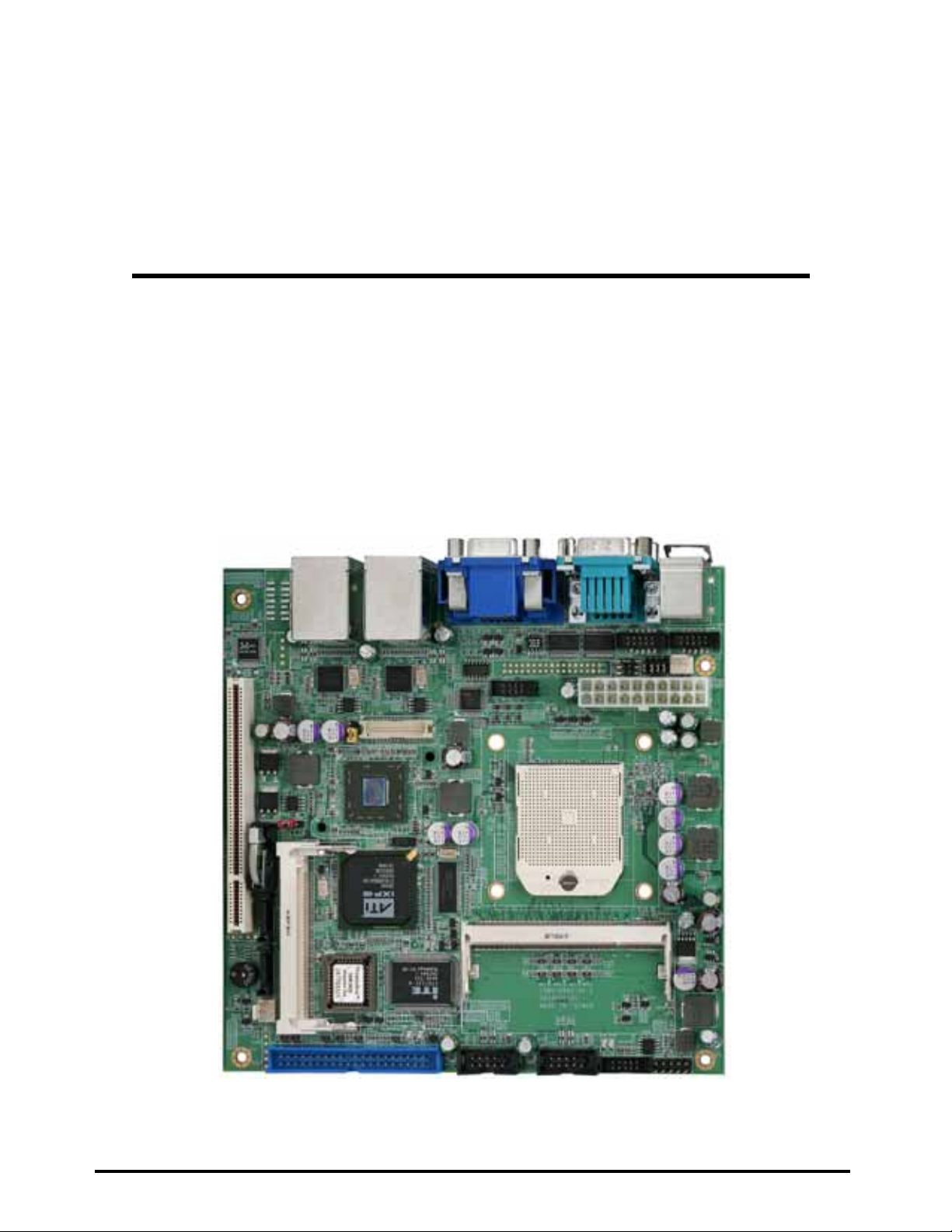
LV-681
Mini-ITX motherboard
User’s Manual
Edition: 1.00
2007/04/09
LV-681 User’s Manual
1
Page 2

LV-681 User’s Manual
2
Copyright
The trademarks mentioned in the manual are legally registered to their respective
companies.
Disclaimer
Notice
The written content provided with this produ ct in the property of Taiwan Commate. No part
of this manual may be reproduced, copied, transmitted in any form or by any means without
prior written permission of Taiwan Commate.
Manual Classification
In order to assist in the use of this product, Taiwan Commate has categorized the user
manual. For detailed product information and specifications, please carefully read the
“ Product User Manual ”.
Trademark
All trademarks are the property of their respective holders.
Any questions please visit our website at http://www.commell.com.tw.
Page 3

LV-681 User’s Manual
3
Packing List
Please check package component before you use our products.
☆ LV – 681 board
☆ Quick Installation Guide
☆ CD for manual and drivers
☆ Cable Kit ( CPU cooler, IDE cable, Serial ATA cable, Serial Port cable, I/O
Shield )
Page 4

LV-681 User’s Manual
4
Table Of Contents
General Information
< Introduction >…..……….………………………………………………………………6
< Specification>.................................................................... 錯誤! 尚未定義書籤。
< Block Diagram>...................................................................................................9
<Mechanical Drawing >..........................................................................................9
Hardware Installation
<Connector Location>..........................................................................................12
< List of Connectors >………………………………………………………………….13
<Jumper Locations>.............................................................................................14
< List of Jumpers>………………………………………………………………………14
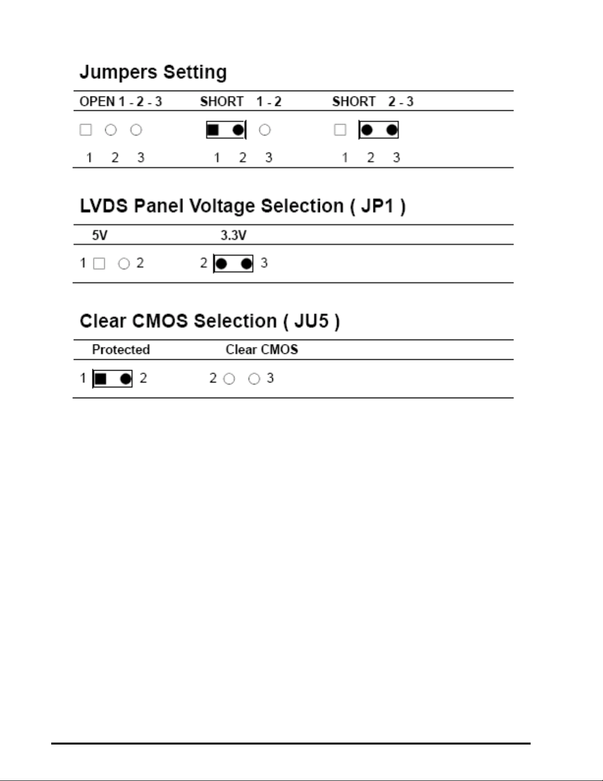
< Jumpers Setting>……………………………………………………………………..15
< LVDS Panel Vo ltage Selection ( JP1 ) >……………………………………………15
< Clear CMOS Selection ( JU5 ) >…………………………………………………….15
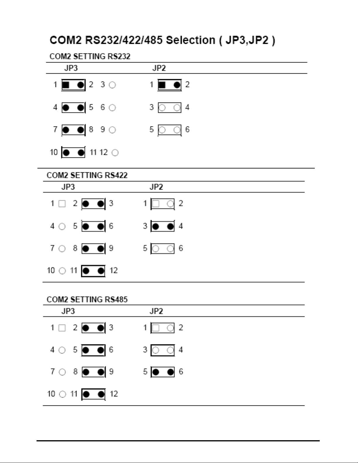
<COM2 RS232/422/485 Slection ( JP3, JP2 )>……………………………………..16
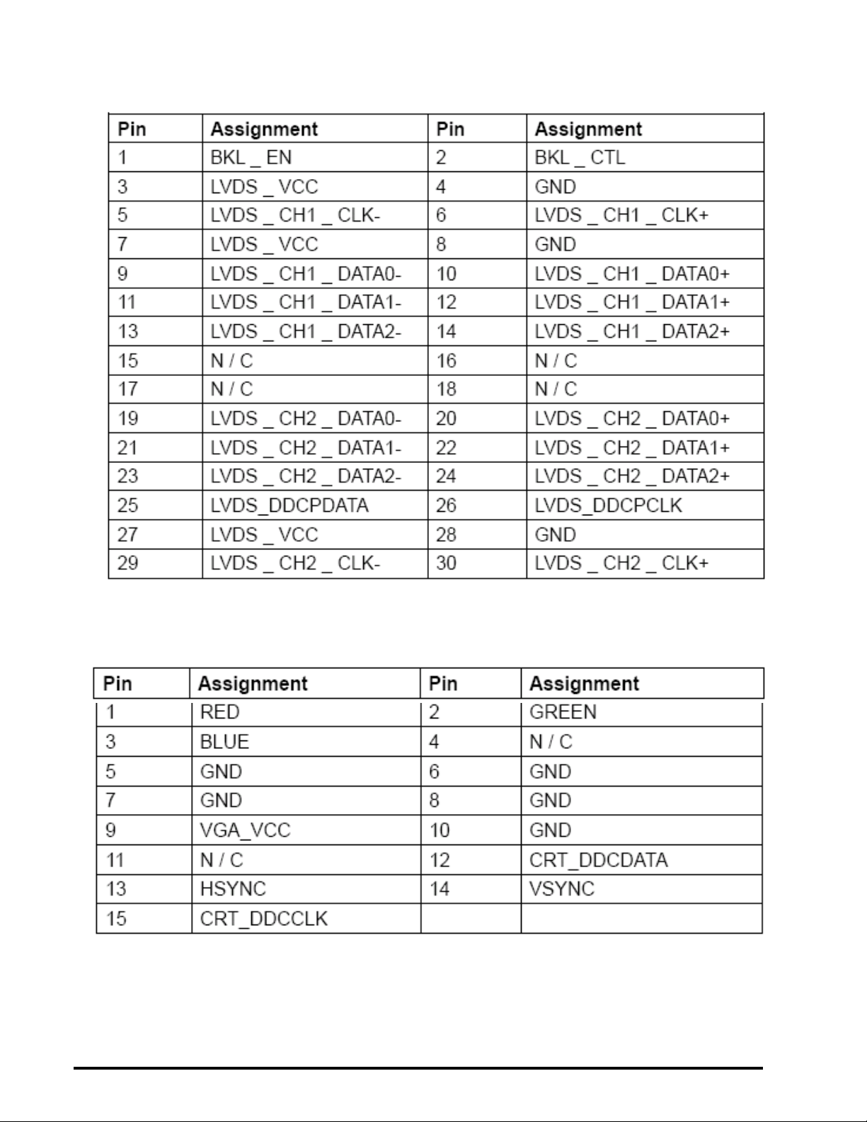
<LVDS Connector ( CN2 )>……………………………………………………………17
< VGA & AUDIO Connector ( CN5 )>…………………………………………………17
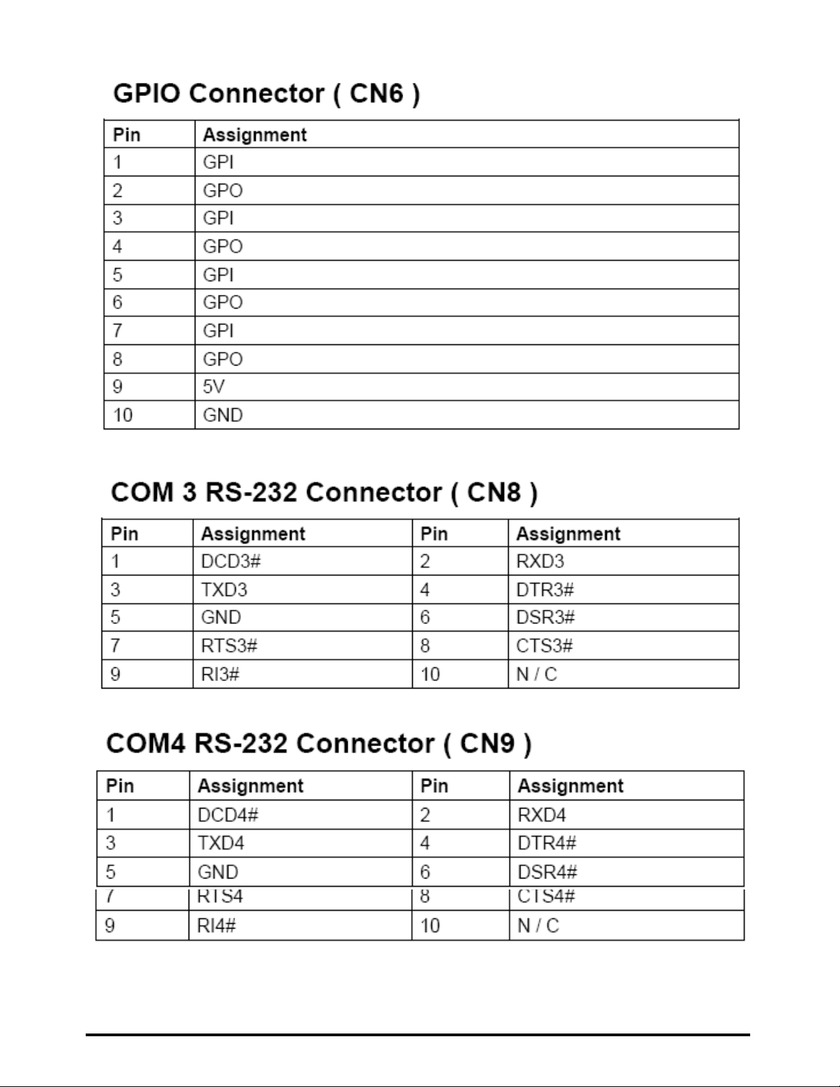
< GPIO Connector ( CN6 ) >…………………………………………………………..18
< COM3 RS-232 Connector ( CN8 ) >………………………………………………..18
< COM4 RS-232 Connector ( CN9 )>………………………………………………...18
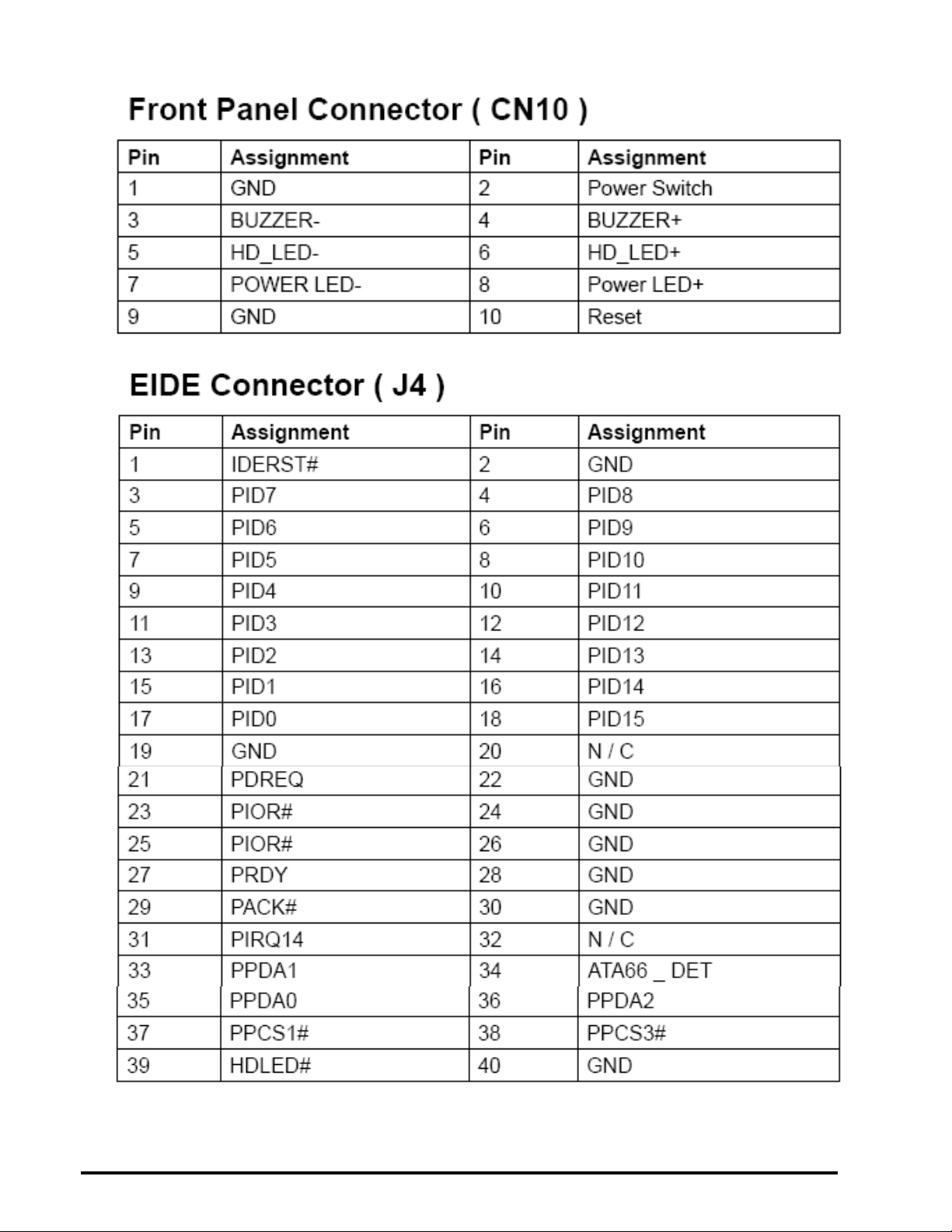
< Front Panel Connector ( CN10 ) >………………………………………………….19
< EIDE Connector Connector ( J4 ) >………………………………………………...19
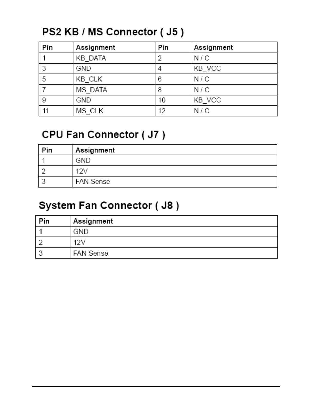
< PS2 KB/ MS Connector ( J5 ) >……………………………………………………..20
< CPU Fan Connector ( J7 ) >…………………………………………………………20
< Systen Fan Connector ( J8 ) >………………………………………………………20
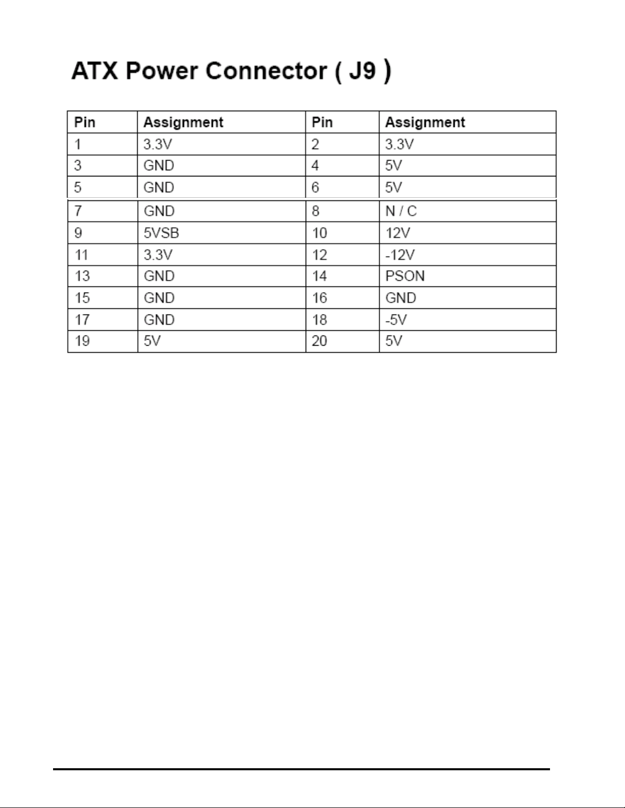
< ATX Power Connector ( J9 ) >……………………………………………………….20
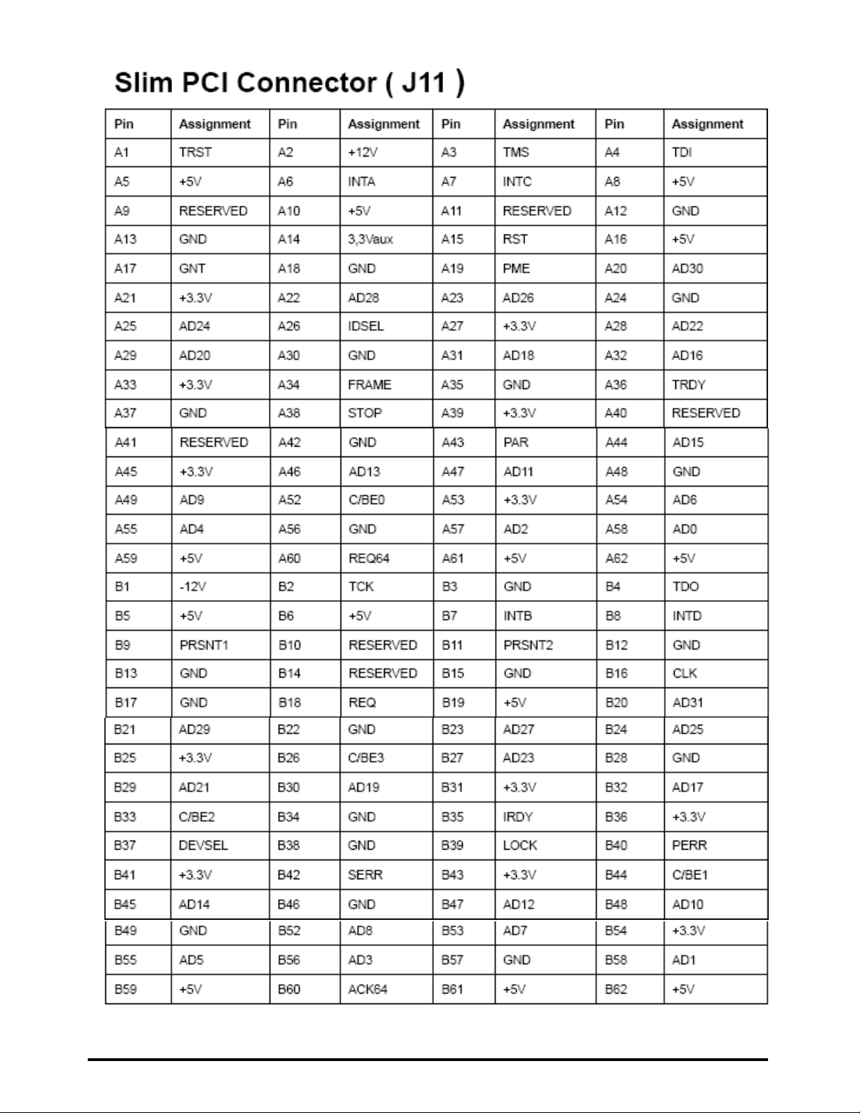
< Slim Floppy Connector ( J11 ) >…………………………………………………….21
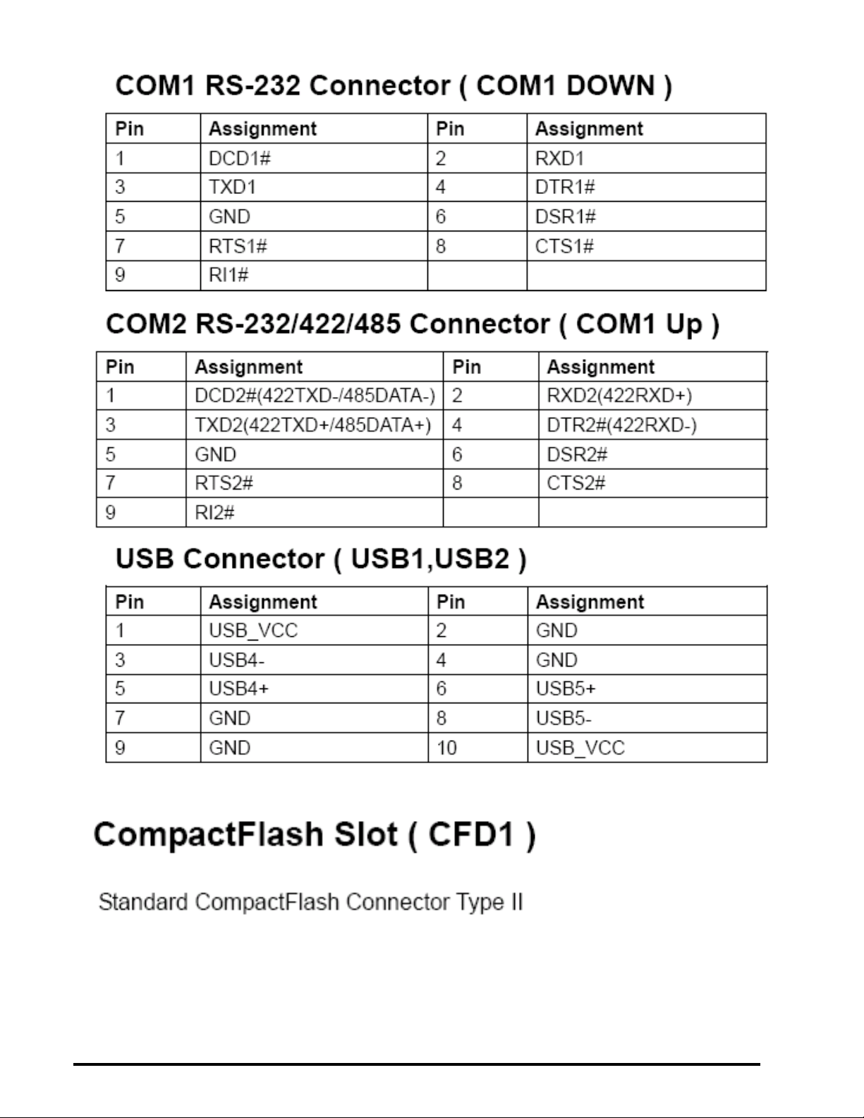
< COM1 RS-232 Connector ( COM1 Down ) >………………………………………22
< COM1 RS-232 Connector ( COM1 Up )>…………………………………………..22
Page 5

LV-681 User’s Manual
5
< USB1 Connector ( USB1 ) >…………………………………………………………22
< USB2 Connector ( USB2 ) >………………………………………………………...22
< CompactFlash Slot ( CFD1 ) >………………………………………………………22
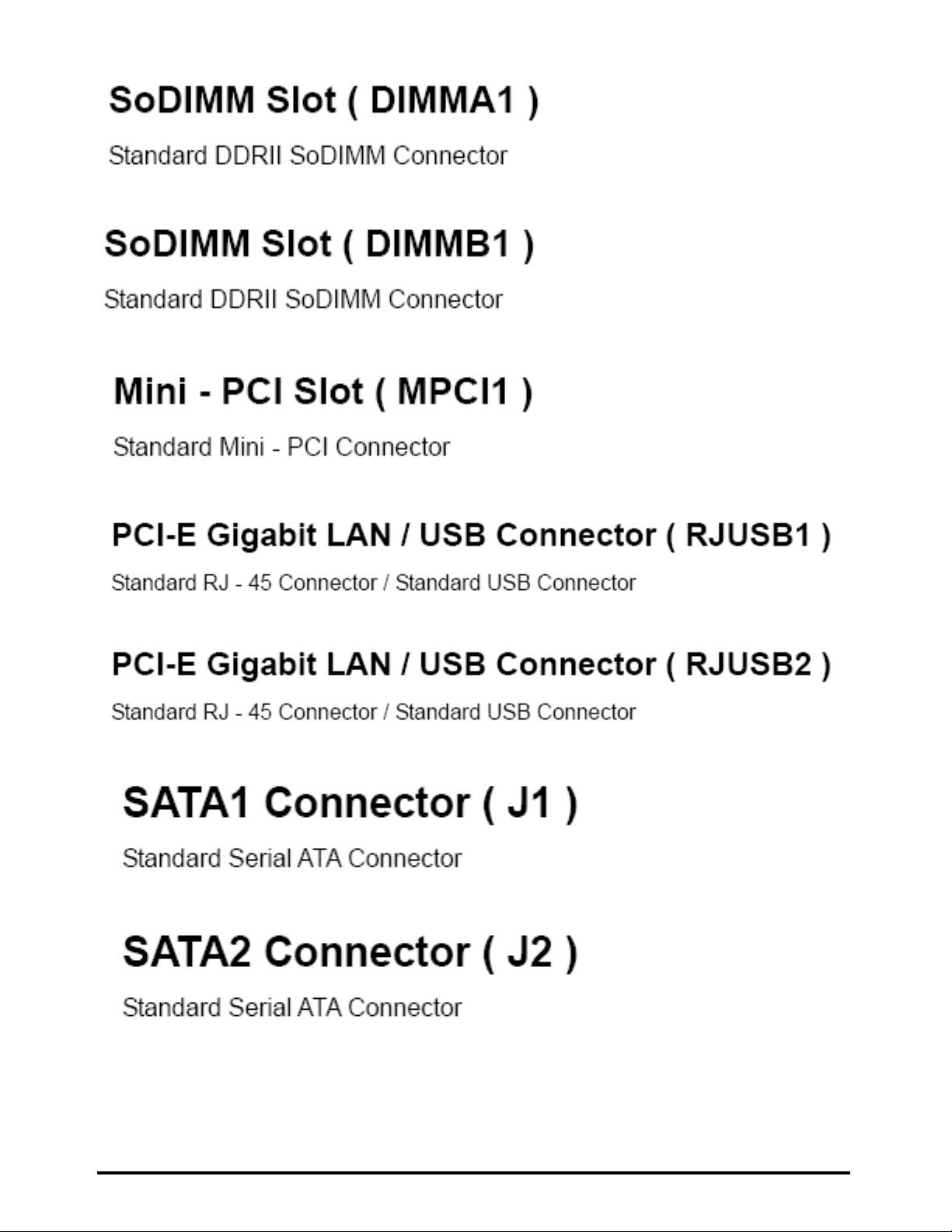
< SoDIMM Slot ( DIMMA1 ) >………………………………………………………….22
< SoDIMM Slot ( DIMMA2 ) >………………………………………………………….23
< Mini - PCI Slot ( MPCI1 ) >…………………………………………………………...23
<PCI-E Gigabit LAN / USB Connector ( RJUSB1 A / B )>…………………………23
<PCI-E Gigabit LAN / USB Connector ( RJUSB1 A / B ) >…………………………23
<SATA1 Connector ( SATA1 ) >…………………………….…………………………23
<SATA2 Connector ( SATA2 ) >…………………………….…………………………23
BIOS Setup
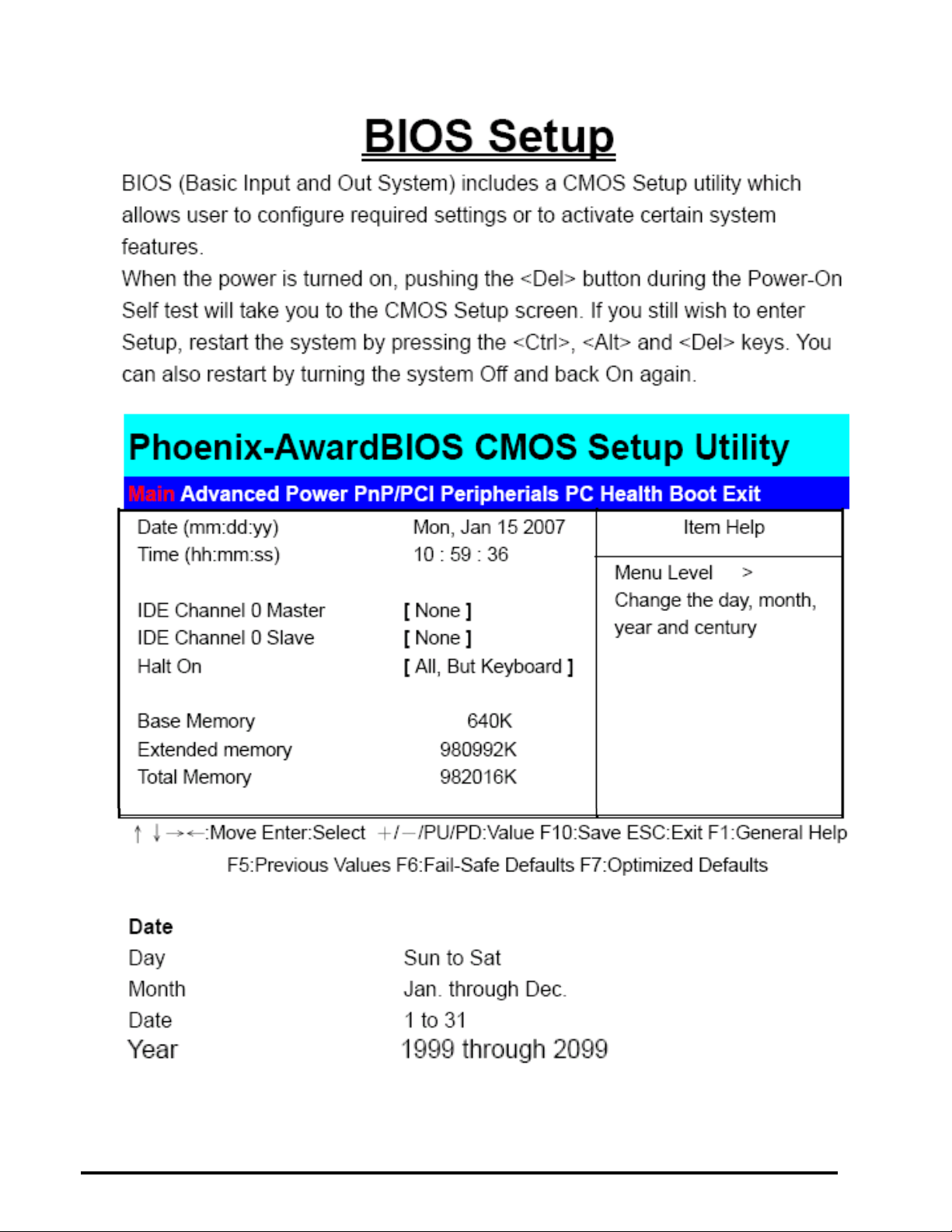
<AwardBIOS CMOS Setup Utilit>…………………………………………………….24
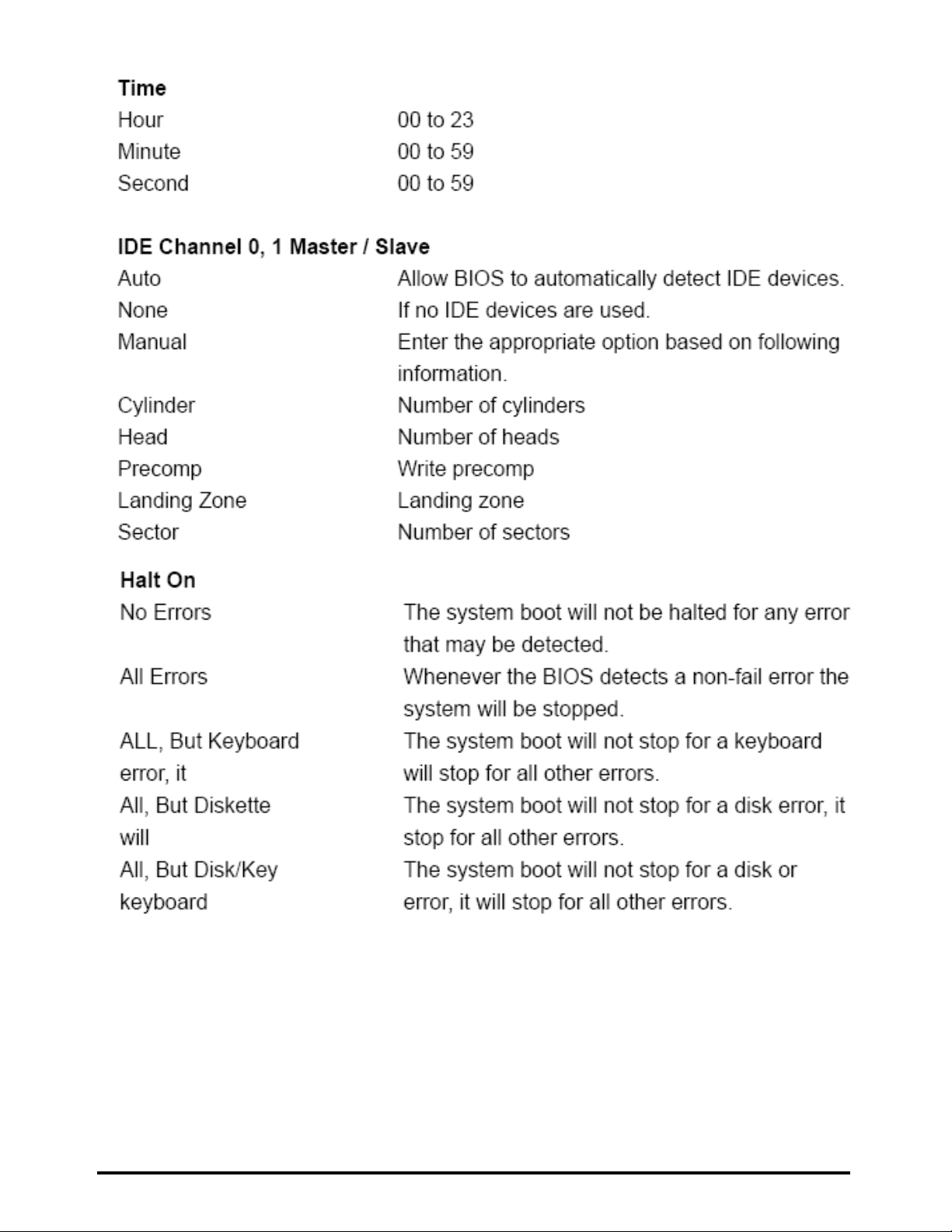
<Main CMOS Features>………………………………………………………………24
<Advanced BIOS Feature>……………………………………………………………26
<Power Management Setup>…………………………………………………………27
<PnP / PCI Configurations>…………………………………………………………..28
<Peripherials Setup>…………………………………………………………………..29
<PC Health Status>……………………..……………………………………………..31
<Boot Status>…………………………………………………………………………..32
<Save & Exit Setup>…………………………………………………………………..33
<Load Optimized Defaults>…………………………………………………………..33
<Exit Without Saving>…….…………………………………………………………..33
<Set Password>…………..…………………………………………………………...33
Appendix
<Watch Dog timer Setting >............................................34
Page 6

LV-681 User’s Manual
6
General Information
Introduction
The LV-681 Mini – ITX board incorporates the ATI RS485M + ATI RS460 chipset , supports
the AMD Turion 64 / Sampron uPGA 638 Pin processors with 800 MHz Front Side Bus
( FSB ), The RS485M integrates an ATI RADEON X-300-based 2D/3D graphics engine,
dual display, The SB460 is a south bridge that integrates key I/O, communications, and
audio features. The board supports DDRII 533 MHz system memory, PCI interface, Gigabit
LAN, Audio, LVDS, CompactFlash, Mini – PCI, Serial ATA, USB 2.0, COM
Multimedia Applications
For multimedia application solution, ATI RS485M chipset provides on board high
performance graphics, 18 – bit LVDS interface, Audio function. This feature will be good of
use in very requirement of the multimedia application.
Widely Expanded Interface
The board provides PCI slot, you can add a third LAN port, and also provides Mini – PCI slot
and CompactFlash Type II slot.
Page 7
LV-681 User’s Manual
7
Specification
Board LV-681 Mini - ITX
CPU AMD Mobile Turion 64 638-pin Processor
Sempron 638-pin Processor
Chipset ATI RS485M + ATI SB460
Memory 2 DDR II SoDIMM slot support DDR II 400 / 533 MHz SDRAM Up
to 2GB
VGA Built in ATI RS485M chipset
I / O Control ATI SB460 + ITE 8712 + Fintek F81216D
LAN 2 Realtek RTL8111B 10 / 100 / 1000Mbit
PCI-Express Giga LAN
Audio ATI SB460 with Realtek ALC655 Codec
IDE 1 40Pin UDMA 66/ 100 / 133 ATA IDE connection
SATA 2 Serial ATA 150MBbit/sec ports
Slot 1 Mini – PCI slot
1 CompactFlash slot
1 PCI slot
BIOS Phoenix – Award 4Mb PnP Flash
GPIO 8 – bit digital I / O
Green Function ACPI 1.0 and APM 1.2 compliant
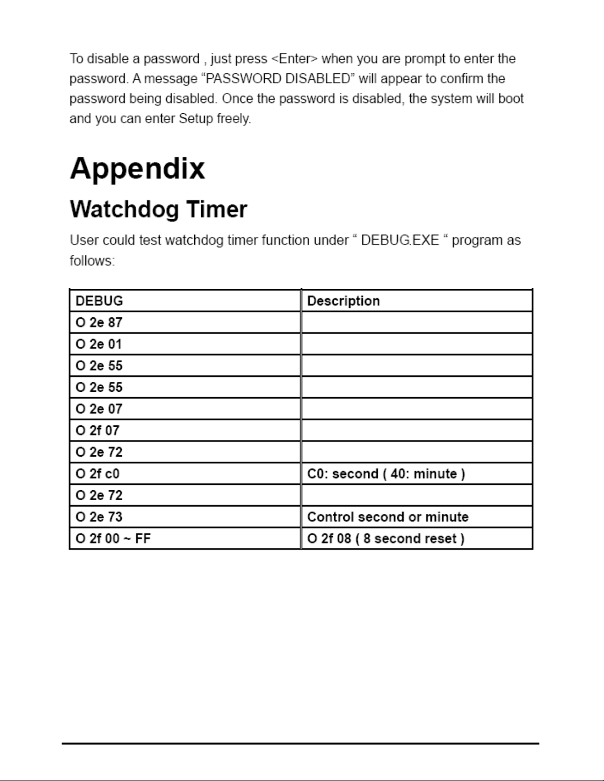
Watchdog Timer System reset programmable watchdog timer with 1 ~ 255 Min. of
time - out
Real Time Clock ATI SB460 built – in RTC with Lithium battery
Form Factor Mini – ITX 6.69 “( L ) x 6.69” ( W ) / 17 x 17 mm
Page 8

LV-681 User’s Manual 8
VGA Display
Chipset ATI RS485M chipset
Memory Shared system memory
Display CRT / LCD monitor with analog for 18 – bit dual channel LVDS interface
Internal I/O Ports
GPIO 1 GPIO Port Connector
USB 2 USB Connector Supports 4 USB ports
Serial Port 1 RS-232 Connector Supports 2 COM ports
IDE 1 40-Pin IDE connector
LVDS 1 18-Bit LVDS Connector
FAN 2 FAN Connector
External I/O Ports
Keyboard/ Mouse 1 PS / 2 ports
Serial Ports 1 external RS – 232 port ( COM 1 )
1 external RS – 232 / 422 / 485 port ( COM 2 )
VGA 1 VGA port
Audio 1 external jack for MIC – In / Line – In / Line – Out
LAN 2 external RJ – 45 ports with LED
USB 4 external USB 2.0 ports
Power And Environment
POWER ATX 20 Pin power connector
TEMPERATURE Operating temperature with 0°C~65°C (32°F~149°F)
Storage temperature with 20°C~80°C (-68°F~176°F)
Page 9
LV-681 User’s Manual
9
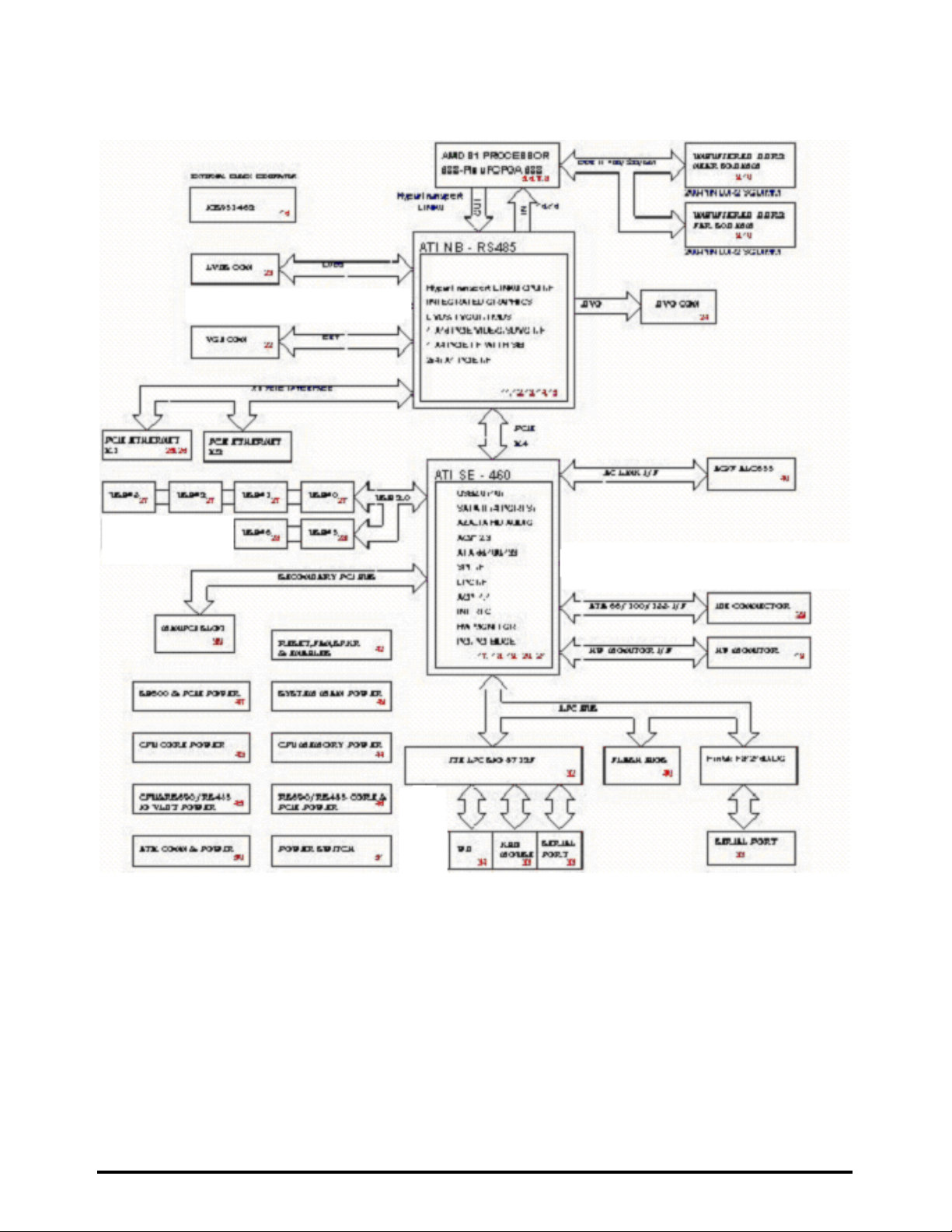
1.3 <Block Diagram>
Page 10
LV-681 User’s Manual 10
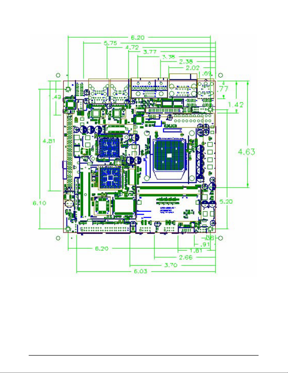
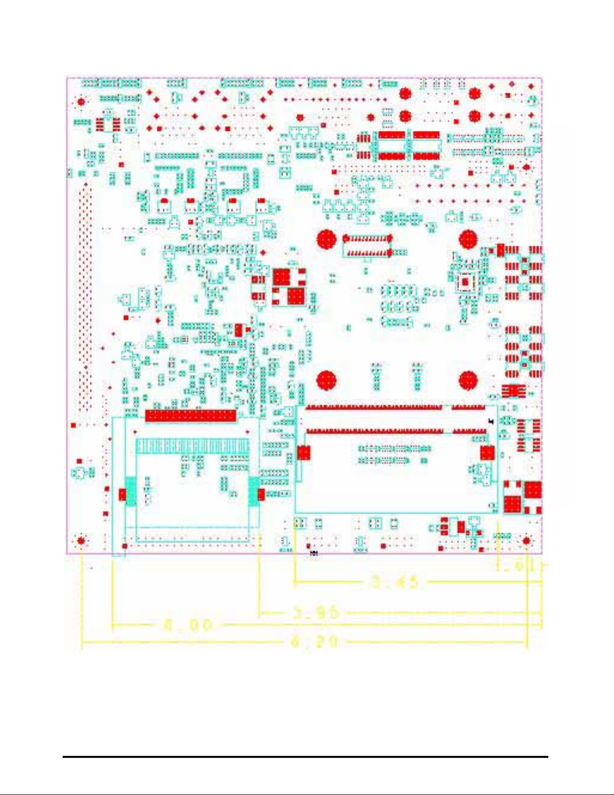
1.4 <Mechanical Drawing >
Page 11
LV-681 User’s Manual
11
Solder Side
mponent Side
Chapter 2 <Hardware Setup>
Page 12
LV-681 User’s Manual
12
Hardware Installation
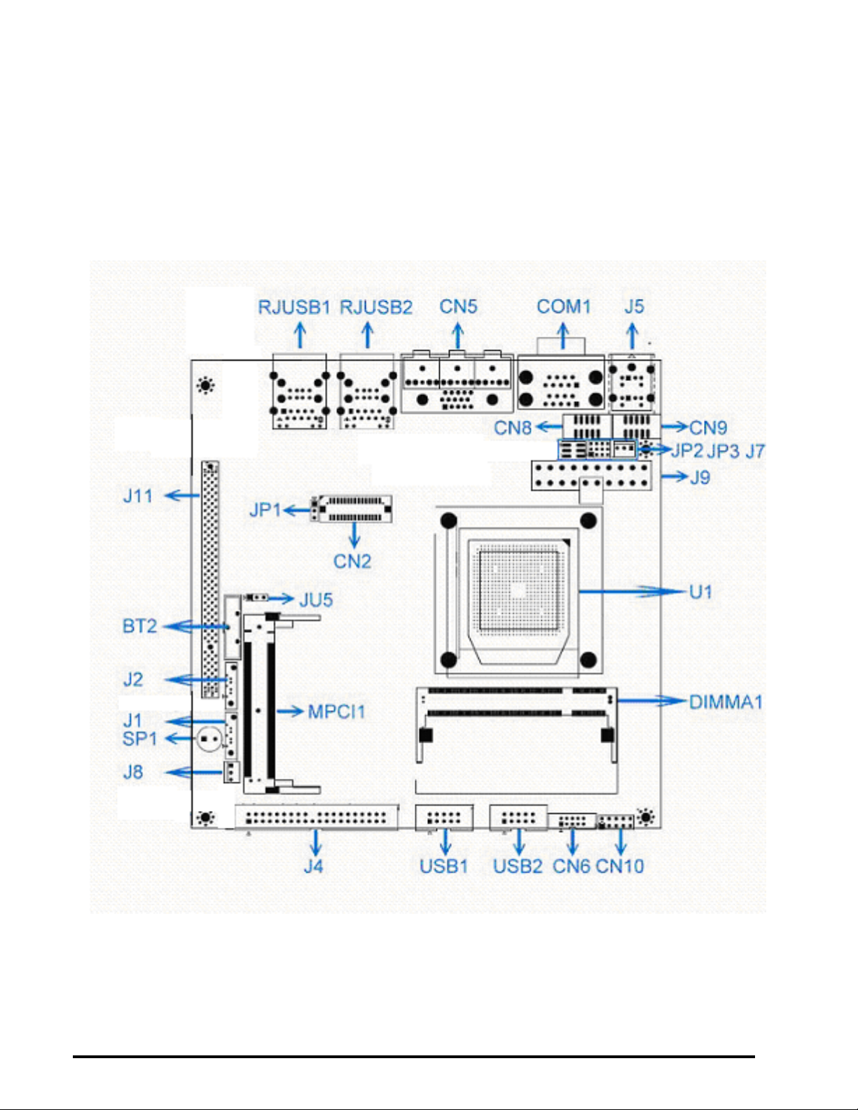
Connectors Location
Component Side
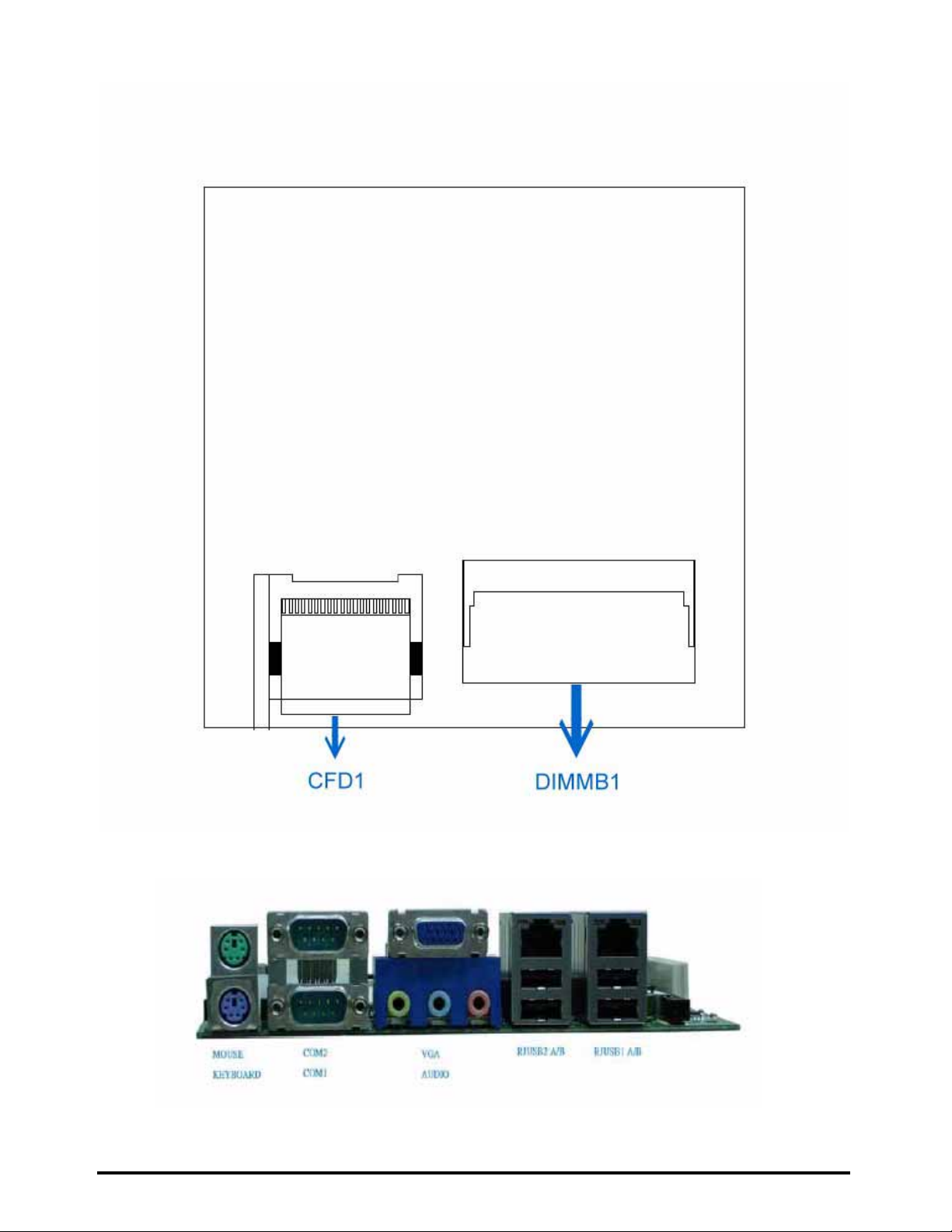
Solder Side
Page 13
LV-681 User’s Manual
13
I / O Panel
Page 14

LV-681 User’s Manual
14
Connectors
Connector Function
CN2 LVDS Connector
CN5 VGA & AUDIO Connector
CN6 GPIO Connector
CN8 COM3 RS-232 Connector
CN9 COM4 RS-232 Connector
CN10 Front Panel Connector
J1 SATA1 Connector
J2 SATA2 Connector
J4 EIDE Connector
J5 PS2 Keyboard / Mouse Connector
J7 CPU Fan Connector
J8 System Fan Connector
J9 ATX Power Connector
J11 Slim PCI Connector
CFD1 CompactFlash Slot
COM1 Down COM1 RS-232 Connector
COM1 Up COM2 RS-232 / RS-422 / RS-485
Connector
DIMMA1 SoDIMM Slot
DIMMB1 SoDIMM Slot
MPCI1 Mini - PCI Slot
RJUSB1 A / B PCI-E Gigabit LAN / USB Connector
RJUSB2 A / B PCI-E Gigabit LAN / USB Connector
USB1 USB1 Connector
USB2 USB2 Connector
Page 15
LV-681 User’s Manual
15
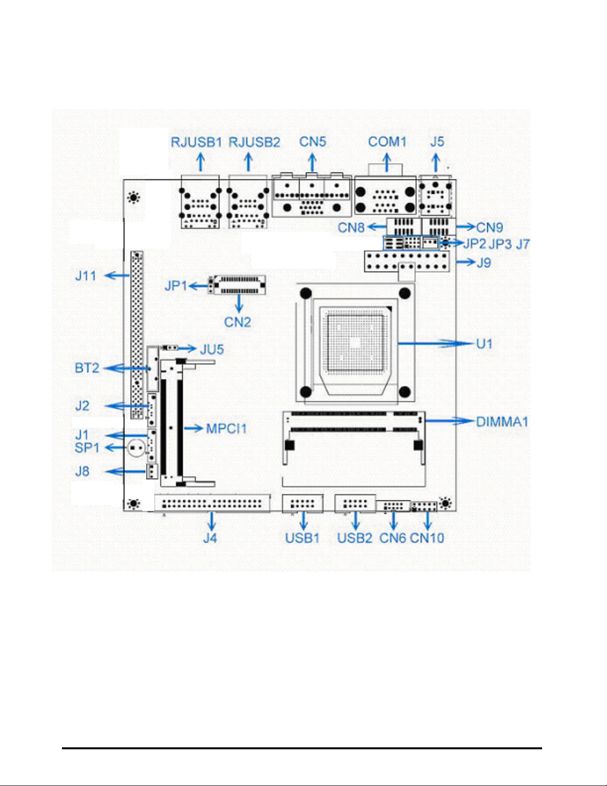
Jumpers Locations
Page 16
LV-681 User’s Manual
16
Page 17
LV-681 User’s Manual
17
Page 18
LV-681 User’s Manual
18
LVDS Connector ( CN2 )
VGA Display Connector ( CN5 )
Page 19
LV-681 User’s Manual
19
Page 20
LV-681 User’s Manual
20
Page 21
LV-681 User’s Manual
21
Page 22
LV-681 User’s Manual
22
Page 23
LV-681 User’s Manual
23
Page 24
LV-681 User’s Manual
24
Page 25
LV-681 User’s Manual
25
Page 26
LV-681 User’s Manual
26
Page 27
LV-681 User’s Manual
27
Page 28
LV-681 User’s Manual
28
Page 29
LV-681 User’s Manual
29
Page 30
LV-681 User’s Manual
30
Page 31
LV-681 User’s Manual
31
Page 32
LV-681 User’s Manual
32
Page 33
LV-681 User’s Manual
33
Page 34
LV-681 User’s Manual
34
Page 35
LV-681 User’s Manual
35
 Loading...