

Page 1

LV-666 User’s Manual
Preface
1
LV-666
MOTHER BOARD
User’s Manual
Edition 1.1
October 19, 2004
Page 2

LV-666 User’s Manual
Preface
2
Copyright Notice
©Copyright 2004
The information contained in this user’s manual and all accompanying documentation is
copyrighted and all rights are reserved. This publication may not, in whole or in part, be
reproduced, transcribed, stored in a retrieval system, translated into any language or
computer language, or transmitted in any form whatsoever without the prior written
consent from the manufacturer, except for copies retained by the purchasers for their
personal archival purposes.
The manufacturer reserves the right to revise this user’s manual and all accompanying
documentation and to make changes in the content without obligation to notify any
person or organization of the revision or change.
IN NO EVENT WILL THE VENDOR BE LIABLE FOR DIRECT, INDIRECT, SPECIAL,
INCIDENTAL, OR CONSEQUENTIAL DAMAGES ARISING OUT OF THE USE OR
INABILITY TO USE THIS PRODUCT OR DOCUMENTATION, EVEN IF ADVISED OF
THE POSSIBILITY OF SUCH DAMAGES. IN PARTICULAR, THE VENDOR SHALL
NOT HAVE LIABILITY FOR ANY HARDWARE, SOFTWARE, OR DATA STORED OR
USED WITH THE PRODUCT, INCLUDING THE COSTS OF REPAIRING, REPLACING,
OR RECOVERING SUCH HARDWARE, SOFTWARE, OR DATA.
All trademarks mentioned in this document are acknowledged.
The specifications in this manual are subject to change without notice.
Page 3

LV-666 User’s Manual
Preface
3
Manual Guide
This manual is designed to help you build a reliable Personal Computer based on
the LV-666 platform.
Chapter 1—Quick Reference
This chapter is for advanced users who want to quickly assemble a system. The
motherboard layout along with jumper and switch settings, and memory
configuration are provided.
Chapter 2—Introduction
This chapter includes an introduction, a checklist of the items that ship with this
motherboard, and a summary of the principal features and components.
Chapter 3—Hardware Installation
This chapter explains how to prepare your motherboard for use and how to make
the various connections to other computer components and peripheral items.
Chapter 4—BIOS Configuration
This chapter explains how to use the system setup utility that is stored in the
motherboard’s firmware.
Chapter 5—Driver and Utility
This chapter briefly describes the drivers and utility programs that are packaged
with the motherboard.
Page 4

LV-666 User’s Manual
Preface
4
Table of Content
1. LV-666 Quick Reference...................................................................................6
1.1 Motherboard Layout .................................................................................6
1.2 I/O Ports ................................................................................................... 7
1.3 Front Panel Connector ............................................................................. 7
1.4 Jumpers.................................................................................................... 8
1.5 PCI Frequency Setting ........................................................................... 10
1.6 Memory Installation ................................................................................ 10
1.7 Connectors............................................................................................. 11
2. Introduction.....................................................................................................12
2.1 Overview ................................................................................................12
2.2 Motherboard Specifications and Features .............................................13
2.2.1. Hardware ................................................................................... 13
2.2.2 Software...................................................................................... 15
2.3 Motherboard Layout ............................................................................... 16
2.4 Embedded Processor............................................................................. 18
2.5 AC’97 Codec .......................................................................................... 18
2.6 Chipset ................................................................................................... 18
3. Hardware Installation......................................................................................19
3.1 Packing List............................................................................................ 19
3.2 Installation .............................................................................................. 20
3.3 Safety Measures .................................................................................... 20
3.4 Connector and Jumper Location............................................................ 21
3.5 Attaching Connectors...................................................................................22
3.5.1 Front Panel Connectors (JP1).................................................... 22
3.5.2 Audio CD-in connector (J2) ........................................................ 23
3.5.3 Audio Line-out connector (JP3) .................................................. 23
3.5.4 Infrared (IR) Connector (IR1) .....................................................24
Page 5

LV-666 User’s Manual
Preface
5
3.5.5 Front IEEE1394 connectors (1394_1 & 1394_2) ....................... 24
3.5.6 Front USB Header (USB1/2 & USB 3/4) .................................... 25
3.5.7 Floppy Driver Connector (FDD1)................................................ 25
3.5.8 IDE connectors (PRIMARY1 & SECONDARY1)........................ 26
3.5.9 Back Panel Connectors.............................................................. 27
3.5.10 Power Supply Connector (ATXPWR1)..................................... 30
3.5.11 CPU/System Fan connectors ................................................... 31
3.5.12 PCI Slot .................................................................................... 31
3.5.13 Serial COM2 connector (COM2) .............................................. 32
3.5.14 Front MIC-in connector (JP2) ................................................... 33
3.5.15 Front AUX connector (J1)......................................................... 33
3.5.16 LVDS connector........................................................................ 34
3.5.17 Optional DVO interface ............................................................ 35
3.6 Installing System Memory ...................................................................... 36
3.7 CPU & CMOS Jumper Setting ............................................................... 37
Appendix A: LVDS Modul e Setup Information.................................................39
A.1: Layout ................................................................................................... 39
A.2 Jumper and Connector Reference......................................................... 39
A.3 BIOS Panel Type Table.......................................................................... 41
Contact Information............................................................................................42
Page 6
LV-666 User’s Manual
Preface
6
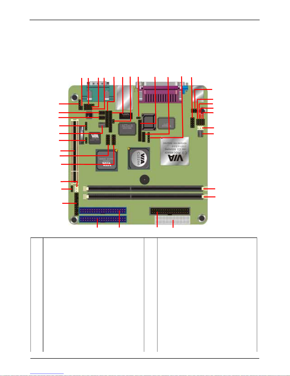
1. LV-666 Quick Reference
This section is for users to get started using the motherboard straight away.
1.1 Motherboard Layout
10
11
13
14
15
16
17
19
20
21
22
23
24 25
26
27 28
29
18
12
32
33
34
35
31
30
36
37
8
9
6
5
7
2
4
3
1
1
2
3
4
5
6
7
8
9
10
11
12
13
14
15
16
17
18
19
20
ATX Power connector (ATXPWR1)
IDE connector (PRIMARY1)
IDE connector (SENCONDARY1)
Floppy connector (FDD1)
184-pin DDR DIMM socket (DIMM1)
184-pin DDR DIMM socket (DIMM2)
Front Panel Connectors (JP1)
Compact Flash Type Jumper (JCFSEL1)
System Fan (CHIPFAN1)
PCI Slot (PCI1)
USB 1/2 connector (USB1/2)
USB 3/4 connector (USB3/4)
CMOS Clear Jumper (CLEAR_CMOS1)
GPIO interface (JP8)
TV-out mode switch (SW1)
IEEE1394 connector (1394_1)
IEEE1394 connector (1394_2)
Audio Line-out connector (JP3)
Audio MIC-in connector (JP2)
Audio SPDIF connector (J3)
21
22
23
24
25
26
27
28
29
30
31
32
33
34
35
36
37
38
39
40
Audio Aux-in connector (J1)
Audio CD-in connector (J2)
DVO interface (JP7)
TMDS interface (J11)
I2C interface (J13)
TV-RST (S3)
LVDS interface (J12)
DVO interface (J10)
IR interface (IR1)
COM2 connector (COM2)
COM2 Jumper (J5)
COM2 Jumper (J6)
COM2 Jumper (J7)
COM2 Jumper (J8)
COM2 Jumper (J9)
CPU Fan (CPUFAN1)
CPU Ratio Switch (SW2)
Page 7
LV-666 User’s Manual
Motherboard Layout
7
Quic
k Referen
ece
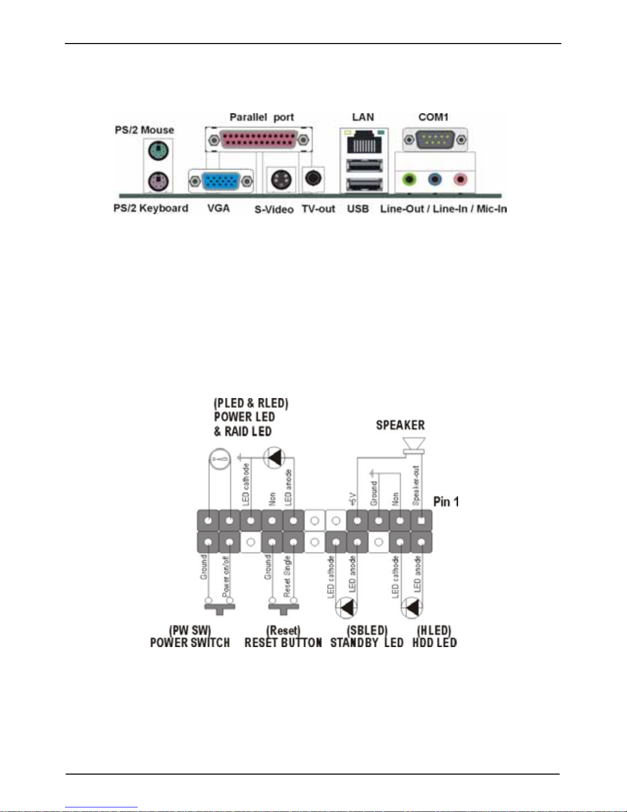
1.2 I/O Ports
1.3 Front Panel Connector
The following illustration shows the front panel connector pin
assignments:
Page 8

LV-666 User’s Manual
Jumpers
8
1.4 Jumpers
CLEAR_CMOS1 Mode
1-2 Clear CMOS
2-3 Normal Operation
Default setting
JCFSEL Compact Flash Mode
1-2 Master
2-3 Slave
Default setting
SW2
CPU RATIO 1 2 3 4 5
3.0x OFF ON ON ON ON
3.5x OFF ON OFF ON ON
4.0x ON OFF ON ON ON
4.5x ON OFF OFF ON ON
5.0x ON ON ON OFF ON
5.5x ON ON OFF ON ON
6.0x OFF OFF ON OFF ON
6.5x OFF OFF OFF OFF ON
7.0x OFF ON ON OFF ON
7.5x OFF ON OFF OFF ON
8.0x ON OFF ON OFF ON
8.5x ON OFF OFF OFF ON
9.0x ON ON ON ON ON
9.5x OFF OFF OFF ON ON
10.0x OFF OFF ON ON ON
10.5x OFF OFF OFF ON OFF
11.0x OFF ON ON ON OFF
11.5x OFF ON OFF ON OFF
Page 9
LV-666 User’s Manual
Jumpers
9
Quic
k Referen
ece
12.0x ON OFF ON ON OFF
12.0x ON ON OFF OFF ON
12.5x ON OFF OFF ON OFF
13.0x ON ON ON OFF OFF
13.5x ON ON OFF ON OFF
14.0x OFF OFF ON OFF OFF
14.5x OFF OFF OFF OFF OFF
15.0x OFF ON ON OFF OFF
15.5x OFF ON OFF OFF OFF
16.0x ON OFF ON OFF OFF
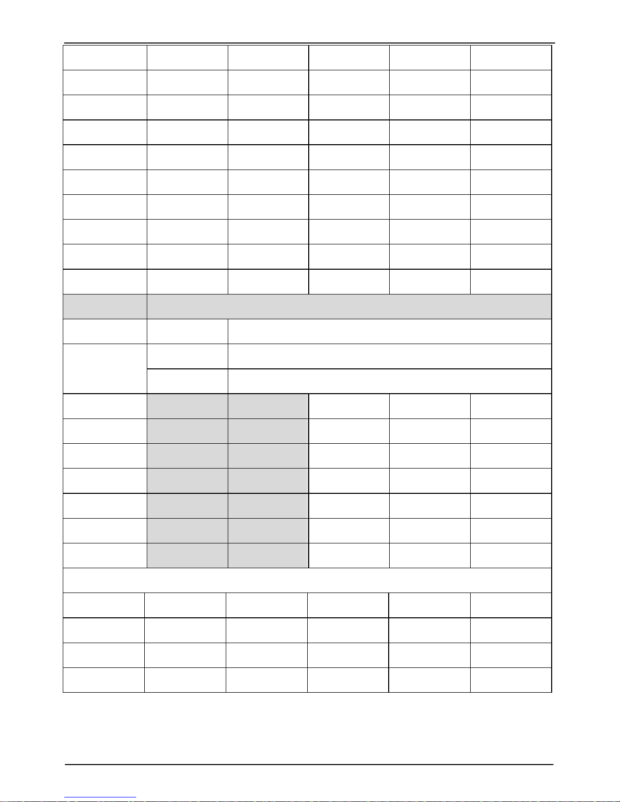
SW1 Switch Number
RESERVE 1-OFF Default
2-ON Enable OVERSCAN
2-OFF Disable
TV-mode 3 4 5
NTSC ON ON ON
NTSC-EIA ON OFF ON
PAL-M ON ON OFF
PAL-BDGHI OFF OFF ON
PAL-Comb-N OFF OFF OFF
PAL-N OFF ON ON
COM2 RS232/485/422 Mode jumper setting
Mode J5 J6 J7 J8 J9
RS232 1-2 1-2 1-2 1-2 1-2
RS422 5-6 1-2 1-2 2-3 2-3
RS485 3-4 2-3 2-3 1-2 1-2
Page 10
LV-666 User’s Manual
Frequency Setting
10
1.5 PCI Frequency Setting
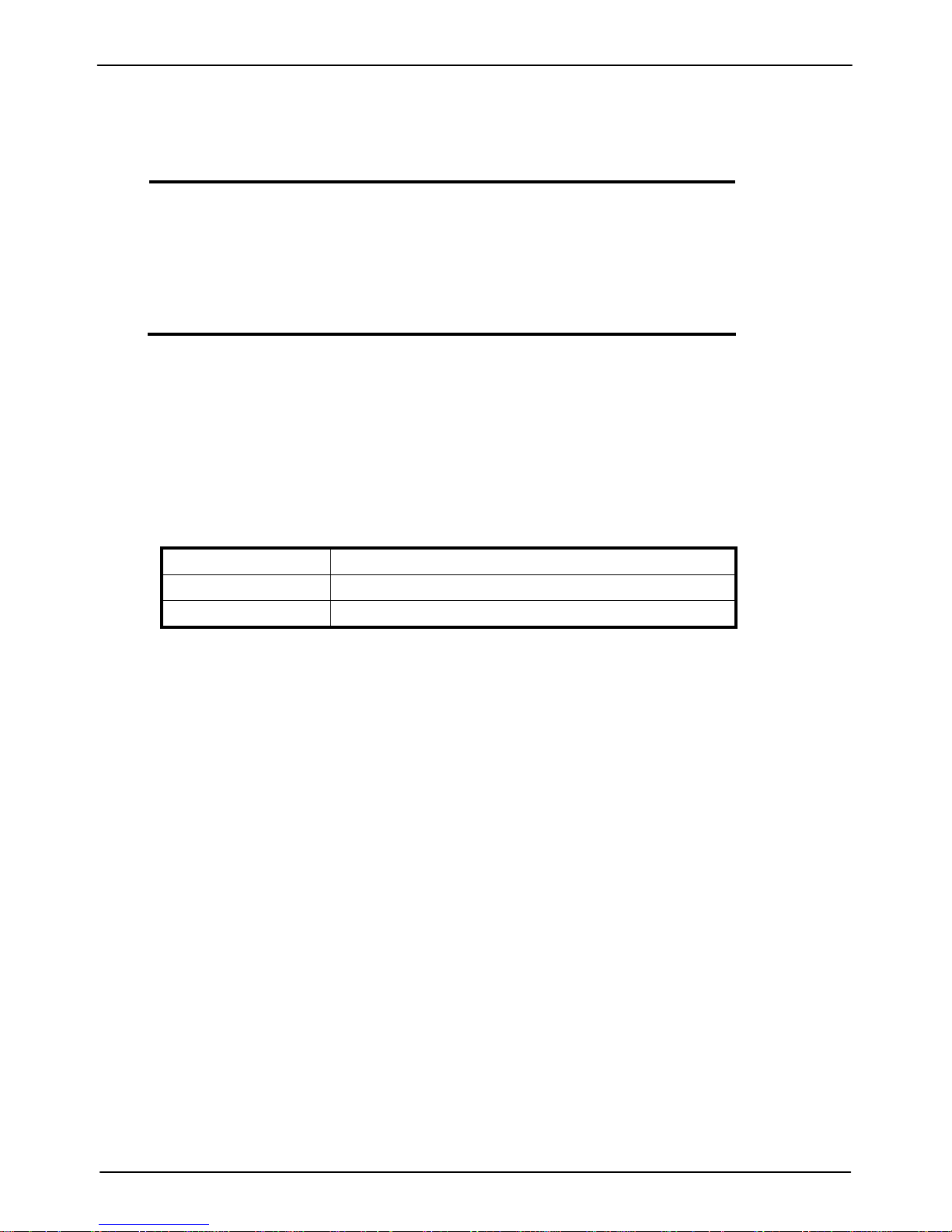
The PCI frequency settings are automatically set by the system
1.6 Memory Installation
Note: This motherboard supports up to two double-sided or
two single-sided DIMMs when the DDR DRAM interface
is operating at 133 MHz. Installing DDR DIMM modules
that exceed these specifications requires that the BIOS
down-shifts the DRAM clocks to 100 MHz through a
two-wire interface of the system clock ge nerator.
184-Pin DIMM DDR SDRAM Memory Configuration.
Each 184-pin DIMM bank can install from 64MB up to 1GB of
PC1600/PC2100/PC2700 compliant 2.5V single or double side buffered with
or without ECC DDR SDRAM modules.
Bank 0 (DIMM1) 64MB, 128MB, 256MB, 512MB, 1GB
Bank 1 (DIMM2) 64MB, 128MB, 256MB, 512MB, 1GB
Total 2 GB
Page 11

LV-666 User’s Manual
Connectors
11
Quic
k Referen
ece
1.7 Connectors
Connector Function Remark
DIMM1 184-pin DIMM Socket Standard
DIMM2 184-pin DIMM Socket Standard
PRIMARY1 40-pin Primary IDE Port Standard
SECONDARY1 40-pin Secondary IDE Port Standard
FDD1 34-pin FDD Port Standard
COM2 10-pin COM2 RS-232/485/422 Serial Port Standard
USB1/2 10-pin 1st / 2nd Hi-Speed USB 2.0 Port Standard
USB3/4 10-pin 3rd / 4th Hi-Speed USB 2.0 Port Standard
IR1 5-pin SIR IrDA Port Standard
ATXPWR1 20-pin ATX Power Connector Standard
1394_1 6-pin IEEE1394 port Standard
1394_2 6-pin IEEE1394 port Standard
J1 4-pin AUX-in connector Standard
J2 4-pin CDIN connector for CD-ROM audio input Standard
J3 5-pin SPDIF connector for Digital Audio Output Standard
JP2 2-pin MIC-in connector Standard
JP3 5-pin Line-out connector Standard
JP7 20-pin DVO interface Standard
JP8 4-pin General Purpose I/O (GPIO) interface Standard
J10 12-pin DVO interface Standard
J11 26-pin TMDS interface Standard
J12 26-pin LVDS interface Standard
J13 2-pin I2C interface Standard
CPUFAN1 CPU FAN connector Standard
CHIPFAN1 System FAN connector Standard
Page 12

LV-666 User’s Manual
Overview
12
Introduction
2. Introduction
2.1 Overview
The high quality LV-666 is a high-performance, enhanced function
motherboard that supports VIA C3/Eden Embedded processor with 133 MHz
front side bus (FSB). This motherboard is designed around the latest VIA
CLE266 Chipset in Mini-ITX form factor.
The motherboard delivers workstation-level performance with bus mastering
EIDE (Enhanced IDE) controller, and concurrent PCI bus. The motherboard
accommodates DDR SDRAM (Synchronous DRAM) memory and supports
ATA66/100/133.
In addition to superior hardware capabilities, provided with this platform are
these features:
ySupport VIA C3/Eden Embedded Processor
ySupports a 100/133 memory bus
ySupports up to 2 GB of PC1600/PC2100 DDR SDRAM
yBus mastering EIDE driver
ySupports 6 x USB ports.
ySupports 5.1 Channel AC97 Audio
ySupports 2 x IEEE1394 firewire connector
ySoft-off APM (Advanced Power Management)
yACPI (Advanced Configuration and Power Interface)
yBIOS upgrade
Page 13

LV-666 User’s Manual
Motherboard Specifications and Feat ures
13
App
endix
2.2 Motherboard Specifications and Features
2.2.1. Hardware
General Specification
Form Factor Mini-ITX at 170 x 170 mm (L x W)
CPU VIA C3/Eden Embedded processor at 133MHz FSB
Memory 2GBytes DDR200/266 SDRAM on 2 x 184-pin DIMM socket
Chipset VIA CLE266 and VT8235
BIOS Phoenix-Award 2Mb PnP flash BIOS
Green Function Power saving mode includes doze, standby and suspend modes. ACPI version 1.0
and APM version 1.2 compliant
Real Time
Clock
VIA VT8235 built-in RTC with lithium battery
Enhanced IDE PCI enhanced IDE interface supports dual channels and up to 4 ATAPI devices at
UltraATA/100/133
Two 40-pin IDE ports
Expansive Slot One PCI slot supports up to 2 bus master PCI bus interface via the additional riser
card
Compact Flash One Compact Flash Type I/II socket
Multi-I/O Port
Chipset VIA VT8235 integrated with Winbond W83697HF Super I/O controller
Serial Port One external RS-232 serial port with 16C550 compatible UART and 16 bytes FIFO
and one internal jumper selectable RS232/485/422 serial port
USB Port 6 x Hi-Speed USB 2.0 ports with 480 Mbps of data transfer rate
2 x external and 4 x internal USB ports
Parallel Port One external bi-direction parallel port with SPP/ECP/EPP mode
Floppy Port One FDD port supports up to two FDD
IrDA Port One IrDA compliant Infrared interface supports SIR
K/B & Mouse External PS/2 keyboard and mouse ports on rear I/O panel
Page 14

LV-666 User’s Manual
Motherboard Specifications and Features
14
Introduction
VGA Display Interface
Chipset VIA CLE266 built-in internal AGP 4X 2D/3D graphics
Frame Buffer Size BIOS selectable 8/16/32/64MB with system shared memory
2D Engine 128 bit
3D Engine 1 Pipe, 2 Texture, dedicated
MPEG-2
Hardware
Acceleration
Slice Layer, IDTC & Motion Compensation
Video Support 2 video stream + Alpha Channel
Dual View
Support
2 Contents, 2 Refresh Rates, 2 Resolution
Connector External DB15 female connector on rear I/O panel
Internal 26-pin LVDS connector
TV-out Interface
Chipset VIA CLE266 integrated with AITech AIT2139KL Codec
TV Mode Support both of NTSC and PAL mode
Connector External S-video and RCA Jack on rear I/O panel
Ethernet Interface
Chipset VIA PRO/100+ LAN interface with VT6103 PHY
Type 10Base-T / 100Base-TX, auto-switching Fast Ethernet
Full duplex, IEEE802.3U compliant
Connector External RJ45 connector with LED on rear I/O panel
Audio Interface
Chipset VIA VT8235 with Realtek ALC650 AC’97 3D audio codec
Interface 5.1 channel 3D audio with front (R/L), rear (R/L), center and bass
S/P DIF digital audio encoding signal input and output
Line-in, line-out, CD-in and MIC-in
Connector External three phone jack for 5.1 channel audio on rear panel
External S/P DIF connector on rear panel
Internal 10-pin header for line-in/-out, MIC-out, 4-pin header for CD-in
Page 15

LV-666 User’s Manual
Motherboard Specifications and Feat ures
15
App
endix
IEEE1394 Interface
Chipset VIA VT6307S PCI IEEE1394 controller
Interface IEEE1394 with 100/200/400 Mbps of data transfer bandwidth
Connector 2 x internal IEEE1394 connector
Power and Environment
Power Requirement 20-pin ATX power connector
Dimension 170 (L) x 170 (H) mm, Mini-ITX form factor
Temperature Operating within 0 ~ 60oC (32 ~ 140oF)
Storage within -20 ~ 85
o
C (-4 ~ 185oF)
2.2.2 Software
BIOS
AWARD AGP/PCI BIOS
2M-bit Flash BIOS with ESCD (Extended System Configuration Data)
block
Supports APM, Plug and Play, Multi-Boot, DMI and EIDE devices
Supports ACPI
Supports high-capacity LS-120 and ZIP removable media drive
Driver and
Utility
IDE Bus mastering Ultra DMA driver
AC97 codec audio driver
Flash utility for BIOS upgrade
System Environment Monitoring Utility
Operating
System
Operates with MS_DOS, Windows 3.x/9x/ME/XP/2000/NT, OS/2,
Novell NetWare/UnixWare 1.1, and SCO Unix 4.2
Page 16
LV-666 User’s Manual
Motherboard Specifications and Features
16
Introduction
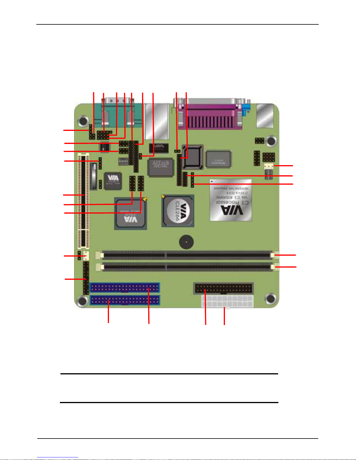
2.3 Motherboard Layout
11
12
13
14
17
16
1518 19
20
23
24
10
27
25
26
6
21
22
7
5
8
Note: Because of optional items and design changes, your
motherboard may not be identical to the one shown in the
illustration.
9
3
4
2
1
Page 17

LV-666 User’s Manual
Motherboard Layout
17
App
endix
Key to Motherboard Function
NO. Name Function
1 ATXPWR1 Standard ATX Power Connector
2 PRIMARY1 40-pin IDE1 Connector
3 SECONDARY1 40-pin IDE2 Connector
4 JP1 Front Panel Connector
5 CHIPFAN System FAN
6 PCI1 32-bit PCI Slot
7 DIMM1 184-pin DDR SDRAM Socket
8 DIMM2 184-pin DDR SDRAM Socket
9 FDD1 26-pin Floppy Connector
10 JP8 4-pin General Purpose I/O Connector
11 JP3 5-pin Line-out Connector
12 JP2 2-pin MIC-in connector
13 J3 5-pin SPDIF connector
14 J1 4-pin AUX-in connector
15 J2 4-pin CD-IN connector
16 1394_1 2 x 3-pin IEEE1394 connector
17 1394_2 2 x 3-pin IEEE1394 connector
18 JP7 20-pin DVO interface
19 J11 26-pin DVO interface
20 J13 2-pin I2C interface
21 USB1/2 10-pin USB1/2 connector
22 USB3/4 10-pin USB3/4 connector
23 S3 TV reset connector
24 J12 26-pin LVDS interface
25 J10 12-pin DVO interface
26 IR1 5-pin IR interface
27 CPUFAN CPU fan connector
Page 18

LV-666 User’s Manual
Key to Motherboard Function
18
Introduction
2.4 Embedded Processor
The board supports embedded VIA C3/Eden EBGA368 processor from
300MHz to 1GHz. The C3 E-series provide best C/P rate performance, and the
Eden series provide low power consumption solution.
2.5 AC’97 Codec
The board is integrated with Realtek ALC650 codec. The ALC650 is an 18-bit,
full duplex, AC’97 2.2 compatible stereo audio codec. The ALC650 incorporates
proprietary converter technology to achieve a high SNR, greater than 90 dB. The
ALC650 AC'97 CODEC supports multiple CODEC extensions with independent
variable sampling rates and built-in 3D effects.
2.6 Chipset
The board is integrated with VIA CLE266 and 8235 chipset, supports VIA
embedded C3/Eden processor for low power consumption. The key features are
below:
· 100/133MHz DDR/SDR Memory bus settings
· Support for Integrated VIA AGP 4X 2D/3D Graphics
· Supports up to 2.0GB DDR200/266 SDRAM
· V-Link 266MB/s high bandwidth North/South Bridge interconnect
· Integrated 6 channel Surround Sound AC-97 Audio Interface
· Integrated 10/100 Ethernet MAC
· Support for ATA 33/66/100/133
· Support for USB 2.0, 6 USB ports, UHCI compliant
· Advanced power management capabilities including ACPI OnNow
Page 19

LV-666 User’s Manual
Embedded Processor
19
App
endix
3. Hardware Installation
This chapter shows how to build your own system of the board. You may need
the following components to built a fully function system.
1. Mini-ITX chassis with standard ATX power supply.
2. At least one 184-pin DDR200/266 SDRAM module.
3. One Floppy drive.
4. One Ultra DMA 66/100 EIDE hard drive.
5. One CD-ROM.
6. One CRT monitor.
7. One PS/2 keyboard and mouse.
8. One S-Video or RCA wire to connect with TV.
9. One 10/100Mps Ethernet wire to connect with your ADSL modem or HUB.
10. A speaker.
3.1 Packing List
Please check the package list below:
1. 1 x LV-666 motherboard.
2. 1 x IDE 66/100 40-pin ribbon cable.
3. 1 x Floppy 34-pin ribbon cable.
4. 1 x Drivers and Utility CD.
5. 1 x user’s manual.
After removing the motherboard from its anti-static bag, place it
on a grounded or antistatic surface (component side up). Inspect
the motherboard and contact your vendor immediately if it is
damaged
Page 20

LV-666 User’s Manual
Hardware Installation
20
Hardware Installation
3.2 Installation
The LV-666 is designed to fit into a standard Mini-ITX ATX form factor chassis.
The pattern of the mounting holes and the position of the back panel connectors
meet the Mini-ITX ATX system board specification. The chassis comes with
various mounting fasteners, which are made of metal or plastic. It is highly
recommended to use as many metal fasteners as possible to mount the
motherboard in the chassis for better grounding.
To install the motherboard you need to install the DDR memory modules, attach
the connectors, and set the correct CPU speed in the CMOS setup.
3.3 Safety Measures
Computer components and electronic circuit boards can be damaged by
discharges of static electricity. Working on computers that are still connected to a
power supply can be extremely dangerous. Follow the simple guidelines below
to avoid damaging you computer:
1. Always disconnect the motherboard from the ATX power supply, and
disconnect the computer from the power outlet whenever you are working
inside the computer case.
2. If possible, wear a grounded wrist strap when you are installing the
motherboard or working inside the computer case. Alternatively, discharge any
static electricity by touching the bare metal chassis of the computer case, or
the bare metal body of ay other grounded appliance.
3. Hold electronic circuit boards by the edges only. Do not touch the components
on the board unless it is necessary to do so. Do not flex or stress the circuit
board.
Leave each component inside the static-proof packaging that it ships with until you
are ready to use the component for the installation.
Page 21
LV-666 User’s Manual
Installation
21
App
endix
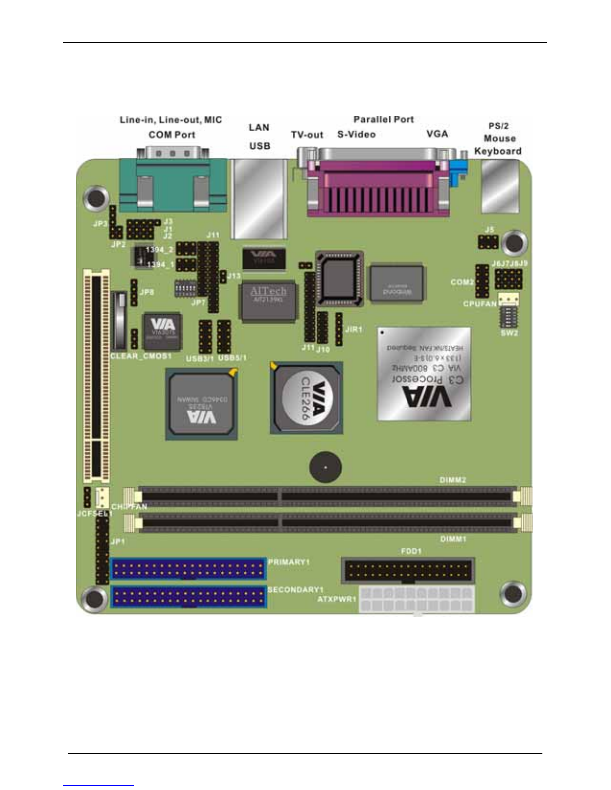
3.4 Connector and Jumper Location
Page 22
LV-666 User’s Manual
Connector and Jumper Location
22
Hardware Installation
3.5 Attaching Connectors
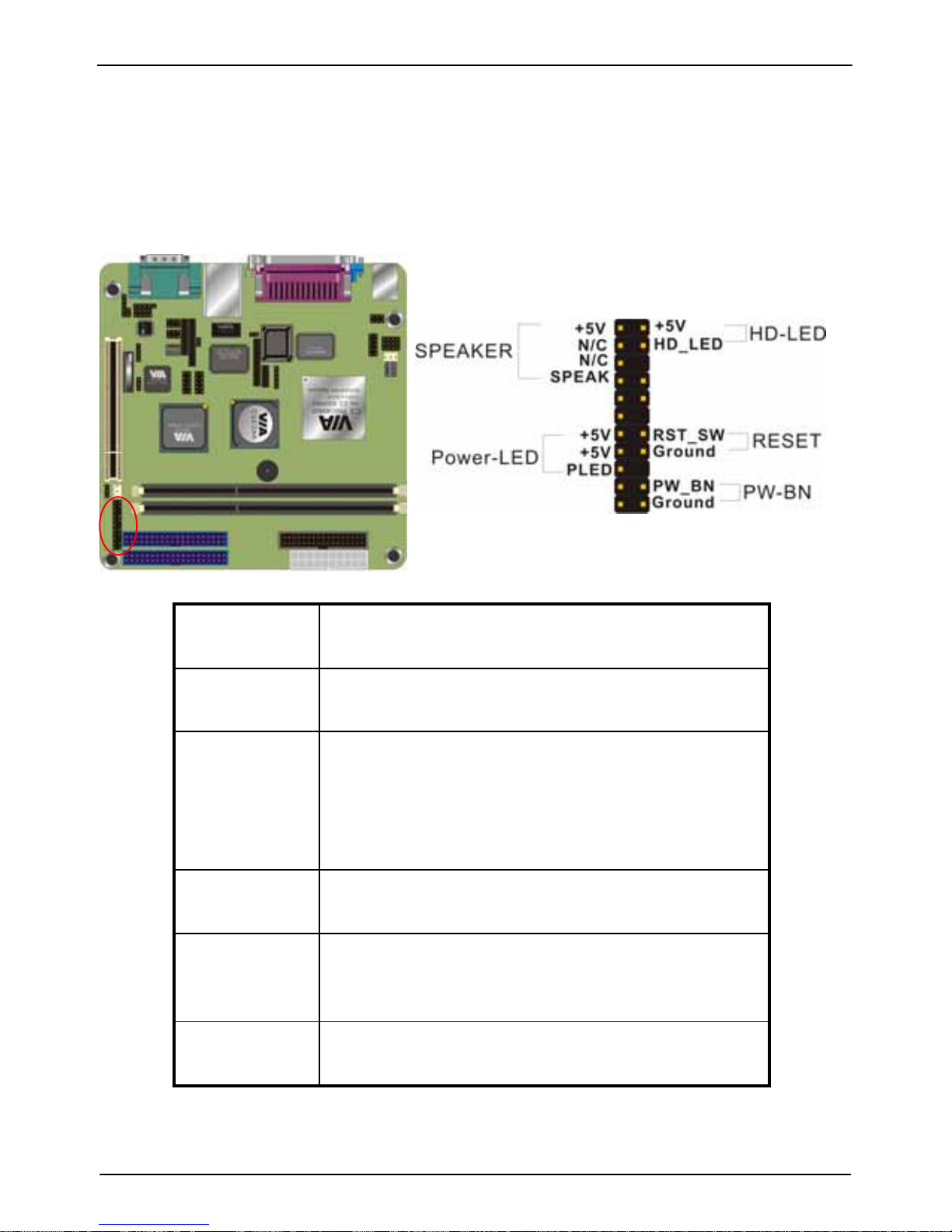
3.5.1 Front Panel Connectors (JP1)
There are seven connectors on the motherboard for speaker, switches, and
indicator lights on the system’s front panel.
PW SW This 2-pin connector connects to the case-mounted
Power button.
RESET This 2-pin connector connects to the case-mounted
reset switch and is used to reboot the system.
SBLED This 2-pin connector connects to the case-mounted
Standby LED to indicate a standby status. The LED
remains Lit even when the system is off to indicate
that AC power is available. When the system enters
standby mode, the LED starts blinking.
HLED This 2-pin connector connects to the case-mounted
HDD LED to indicate hard disk activity.
PWRLED
& RLED
This 5-pin connector connects to the case-mounted
and the power LED. The RLED switch is used to
indicate Raid activity.
SPEAKER This 4-pin connector connects to the case-mounted
speaker.
Page 23
LV-666 User’s Manual
Attaching Connectors
23
App
endix
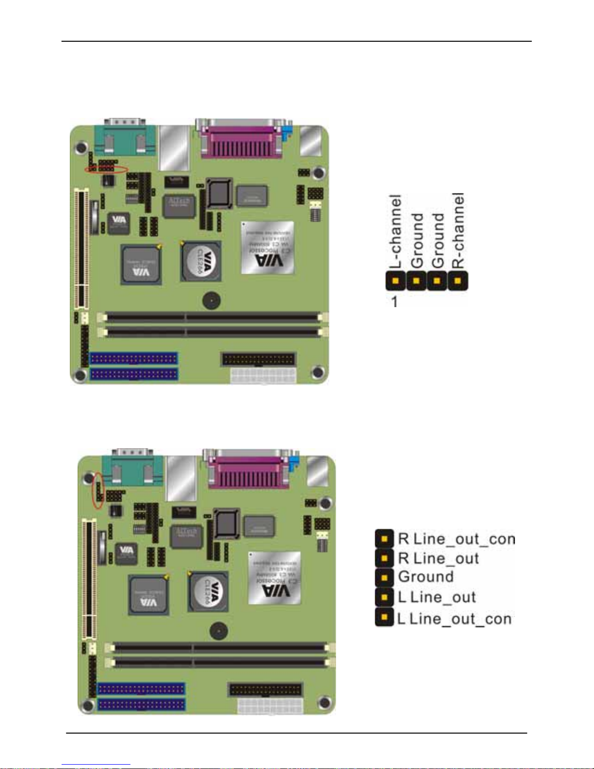
3.5.2 Audio CD-in connector (J2)
This connector enables you to connect a CD-ROM to the motherboard and
receive stereo audio input
3.5.3 Audio Line-out connector (JP3)
Page 24
LV-666 User’s Manual
Attaching Connectors
24
Hardware Installation
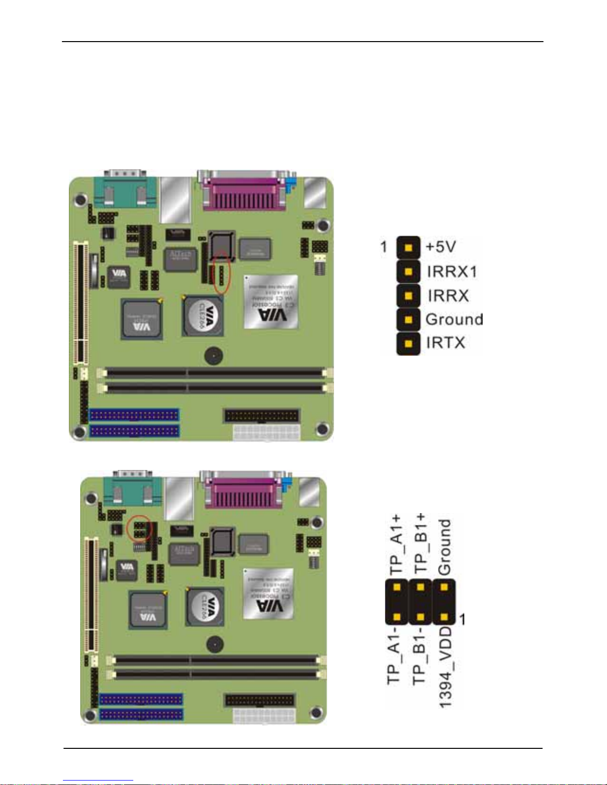
3.5.4 Infrared (IR) Connector (IR1)
This 5-pinheader connects to an optional wireless transmitting and receiving
infrared module via a cable and a bracket. Configure BIOS to enable the IrDA port
if you attach an infrared module to this connector. Refer to Integrated Peripherals
in Chapter 4 for details.
3.5.5 Front IEEE1394 connectors (1394_1 & 1394_2)
Page 25
LV-666 User’s Manual
Attaching Connectors
25
App
endix
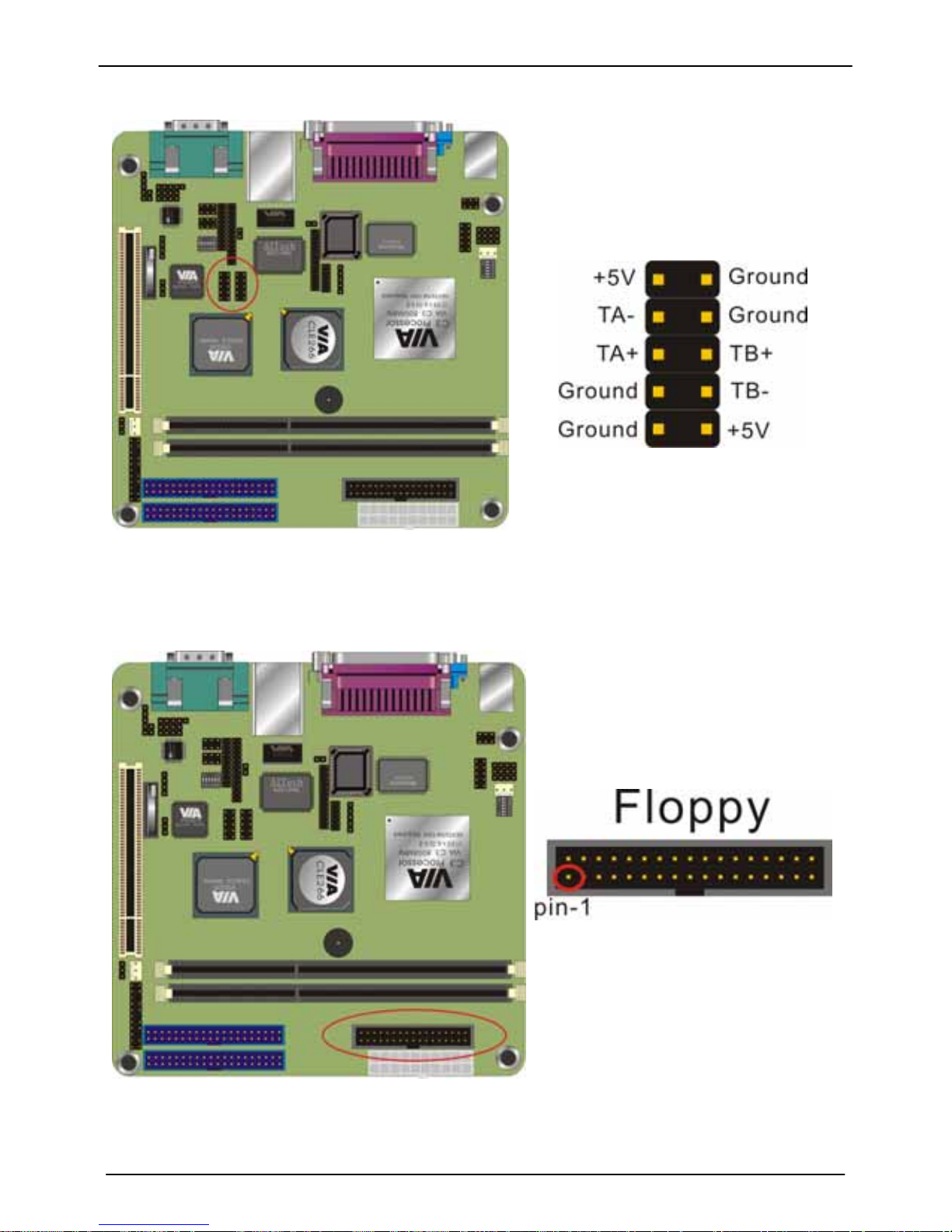
3.5.6 Front USB Header (USB1/2 & USB 3/4)
1
3.5.7 Floppy Driver Connector (FDD1)
Page 26
LV-666 User’s Manual
Attaching Connectors
26
Hardware Installation
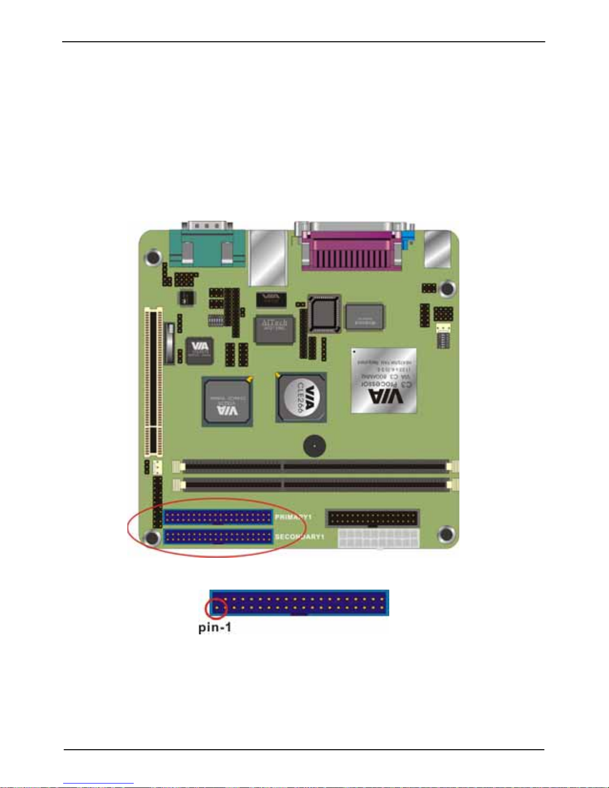
3.5.8 IDE connectors (PRIMARY1 & SECONDARY1)
An IDE drive ribbon cable has two connectors to support two IDE drives. If a
ribbon cable connects to two IDE drives at the same time, one of them has to be
configured as Master and the other has to be configured as Slave by setting the
drive select jumpers on the drive.
Consult the documentation that came with your IDE drive for details on jumper
locations and settings. You must orient the cable connector so that the pin 1 (color)
edge of the cable corresponds to pin 1 of the I/O port connector.
Page 27
LV-666 User’s Manual
Attaching Connectors
27
App
endix
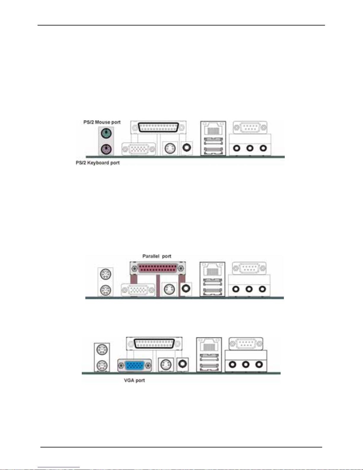
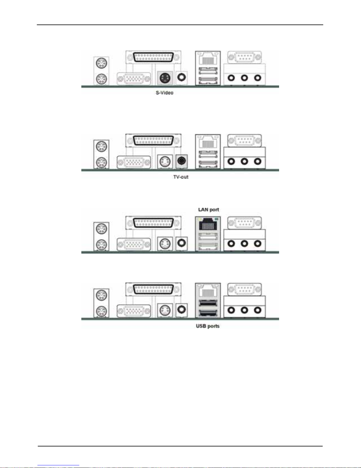
3.5.9 Back Panel Connectors
The back panel provides external access to PS/2 style keyboard and mouse
connectors, two serial ports, one parallel port, dual USB ports, and audio Line-out,
Line-in, MIC-in ports which are integrated on the motherboard. The figures below
show the location of the back panel I/O connectors.
PS/2 Mouse and PS/2 Key board Ports
Connect a PS/2 mouse to the green 6-pin mini DIN connector. The system will
automatically assign IRQ 12 to the PS/2 mouse if one is connected.
Connect a PS/2 keyboard to the purple 6-pin mini DIN connector.
If you want to connect a standard AT size (large DIN) connector,
you must use and adapter.
Parallel Port
Connect a printer or other parallel device to the burgundy-colored 25-pin parallel
port. You can set the parallel port IRQ and parallel port mode in BIOS. Refer to
Integrated Peripherals in Chapter 4 for details.
VGA Port
Connect an external monitor to the blue 15-pin VGA port.
Page 28
LV-666 User’s Manual
Attaching Connectors
28
Hardware Installation
S-Video Port
You can connect S-Video devices to S-Video port on the back panel.
RCA Video (TV-Out)
You can connect RCA Video devices to RCA Video port (TV-Out) on the backpanel.
LAN Port
Connect a device to the LAN port on the back panel.
Universal Serial Bus Ports
You can connect two USB devices or USB hubs to the USB ports.
The USB ports provide a hardware interface for low-speed peripherals such as the
keyboard, mouse, joystick, scanner, printer and telephony devices, and also
support MPEG-1 and MPEG-2 digital video. The USB ports have a maximum
bandwidth of 480 Mbits/sec (equivalent to 60 Mbytes/sec), and up to 127devices
can be attached. Fast devices can use the full bandwidth, while lower-speed ones
can transfer data using a 60 Mbytes/sec sub-channel.
Page 29
LV-666 User’s Manual
Attaching Connectors
29
App
endix
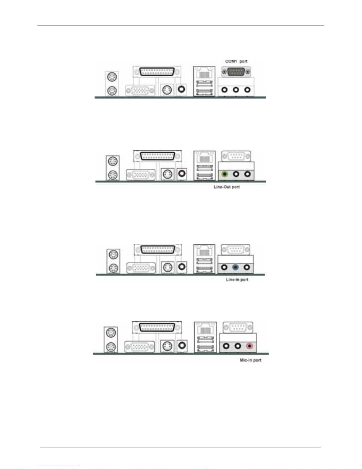
Serial Port
Connect a serial device such as a mouse or modem to the 9-pin serial port. You can set the
serial port IRQs in BIOS. Refer to integrated Peripherals in Chapter 4 for details.
Note: Serial printers must be connected to the serial port.
Audio Line-Out Port
You can connect various audio devices to this audio jack. Connect headphones or powered
speakers to the lime-colored lineout connector.
Audio Line-In Port
You can connect a tape player or another audio source to the light blue Line-in connector to
record audio on your computer or to play audio through your computer’s sound chip and
speakers.
Audio MIC-In Port
You can connect a microphone to the pink microphone connector to record audio to your
computer.
※ For 5.1 channel output
This board can support 5.1 channel audio output, when you connect the 5.1
channel speaker set, after installing audio drivers, the Line-in, Line-out and
MIC-in and let you configure to support Rear, Front and center.
Page 30
LV-666 User’s Manual
Attaching Connectors
30
Hardware Installation
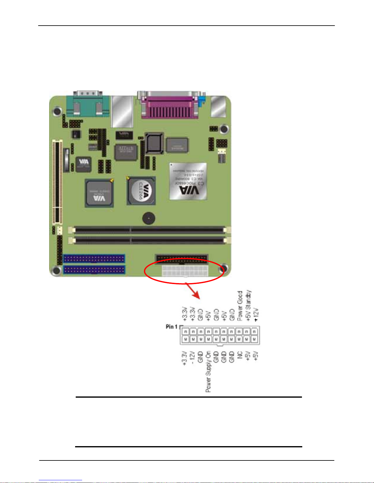
3.5.10 Power Supply Connector (ATXPWR1)
The ATX power supply has a single lead connector with a clip on one side of
the plastic housing. There is only one way to plug the lead into to ATX power
connector. Press the lead connector down until the clip snaps into place and
secures the lead onto the connector.
Warning:
Incorrect installation of the power supply could result in
serious dama
g
e to the motherboard and connected
p
eripherals. Make sure the power supply is unplugged
f
rom the AC outlet before connecting the leads from the
power supply.
Page 31
LV-666 User’s Manual
Attaching Connectors
31
App
endix
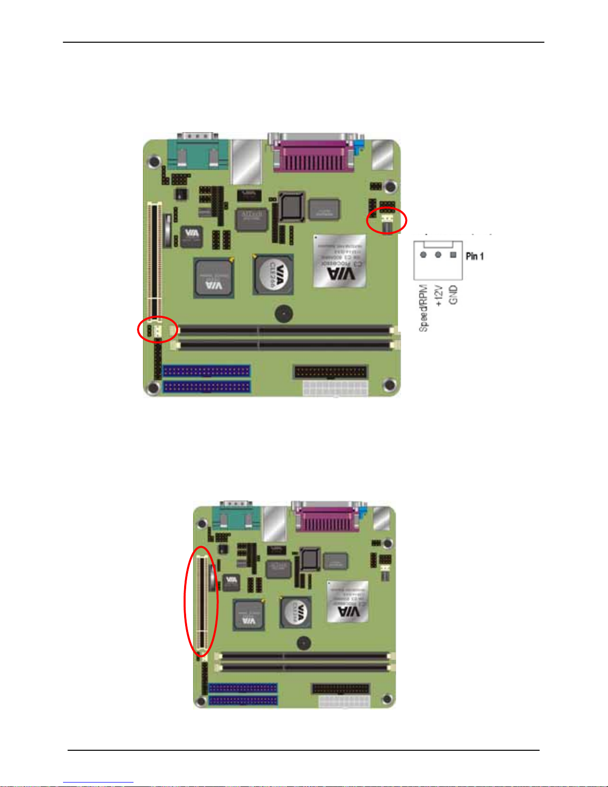
3.5.11 CPU/System Fan connectors
There are two fan connectors on the motherboard for the cooling fans. The
connectors support fans of 12VDC/500mAMP (six watt) or less. When the
system goes into sleep state, fans should be shut down to eliminate audible noise
and reduce power consumption.
3.5.12 PCI Slot
PCI connector is one of equipment interfaces that connect peripheral
equipment and motherboard. Its transfer speed is faster than traditional ISA. PCI is
the mainstream transfer interface for extra adopter.
CHIPFAN
CPUFAN
Page 32
LV-666 User’s Manual
Attaching Connectors
32
Hardware Installation
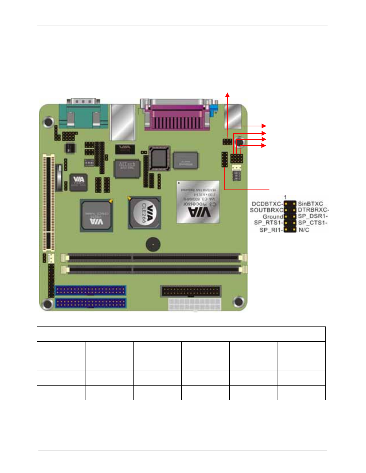
3.5.13 Serial COM2 connector (COM2)
The motherboard provides one onboard serial COM2 connector. The COM2
connector has the same signal with COM1 on the back panel. The COM2 also
support RS485/422 communication mode. Please follow the jumper setting below
to select the mode you need.
J5
J6
J7
J8
J9
COM2
COM2 RS232/485/422 Mode jumper setting
Mode J5 J6 J7 J8 J9
RS232 1-2 1-2 1-2 1-2 1-2
RS422 5-6 1-2 1-2 2-3 2-3
RS485 3-4 2-3 2-3 1-2 1-2
Page 33
LV-666 User’s Manual
Attaching Connectors
33
App
endix
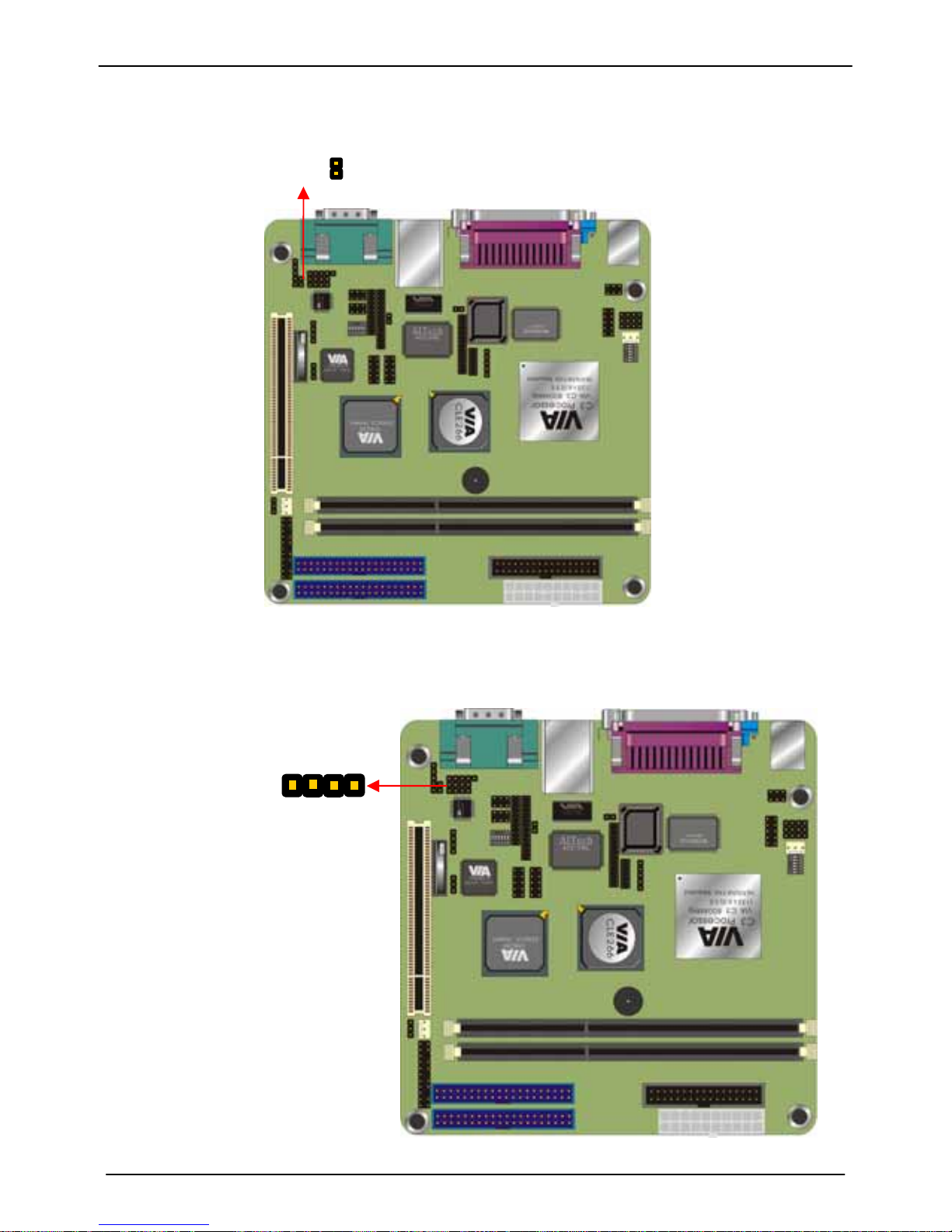
3.5.14 Front MIC-in connector (JP2)
Connect a microphone to the pink microphone connector to record audio to
your computer.
Ground
MICIN
JP2
1
3.5.15 Front AUX connector (J1)
Connector the cable attached to line-out connector on front panel. This
header shared same signal with line-out back panel.
CAUXR
Ground
Ground
CAUXL
Page 34
LV-666 User’s Manual
Attaching Connectors
34
Hardware Installation
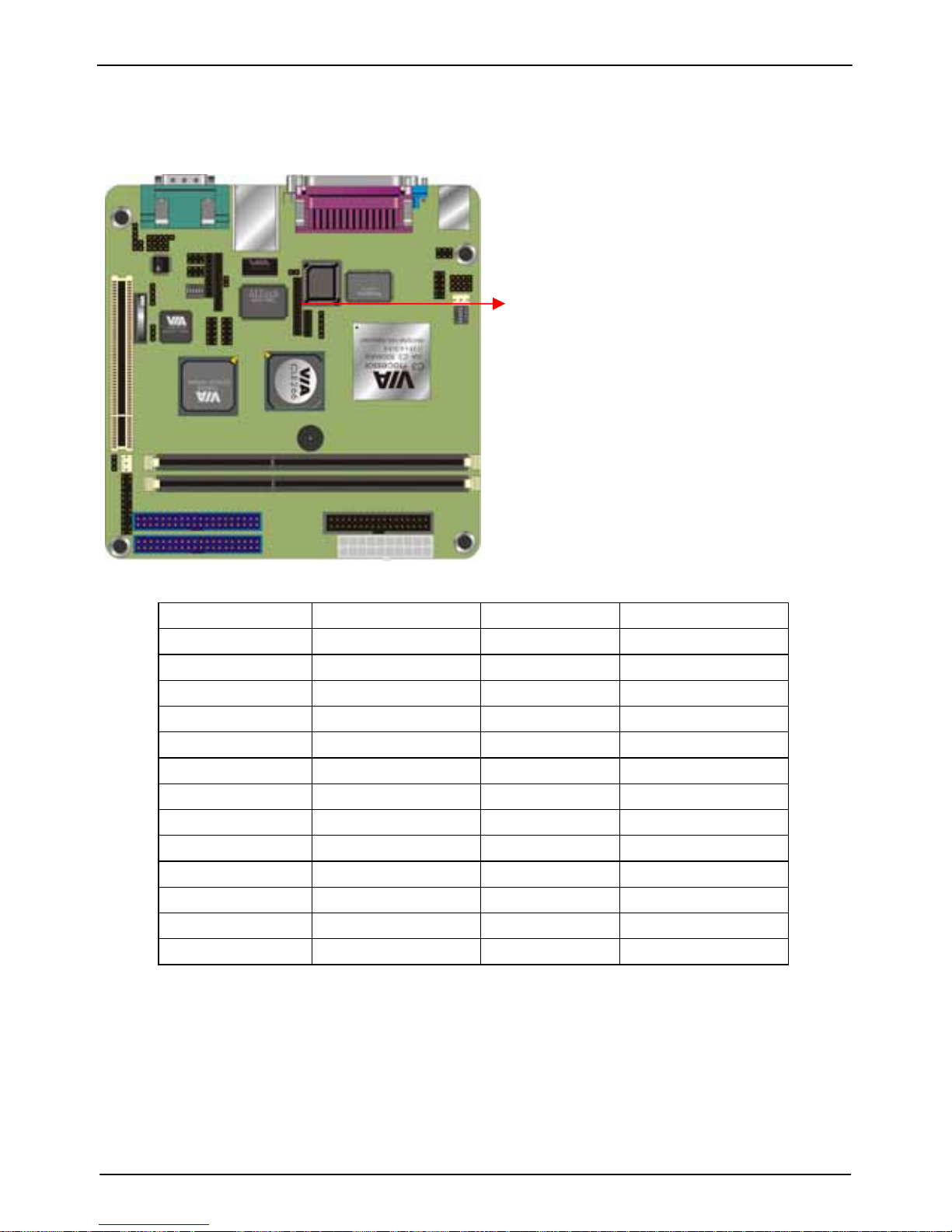
3.5.16 LVDS connector
The board supports LCD LVDS interface, you can use a panel through this
interface.
Pin NO Pin Assignment Pin NO Pin Assignment
1 +3.3V 2 +3.3V
3 TVD0 4 +2.5V
5 TVD1 6 +2.5V
7 TVD2 8 +5V
9 TVD3 10 +5V
11 TVD4 12 Ground
13 TVD5 14 TVBLK
15 TVD6 16 DISPCLK1
17 TVD7 18 DISPCLK0
19 TVD8 20 TVCLK
21 TVD9 22 TVCLKR
23 TVD10 24 TVVS
25 TVD11 26 TVHS
Page 35
LV-666 User’s Manual
Attaching Connectors
35
Hardware Installation
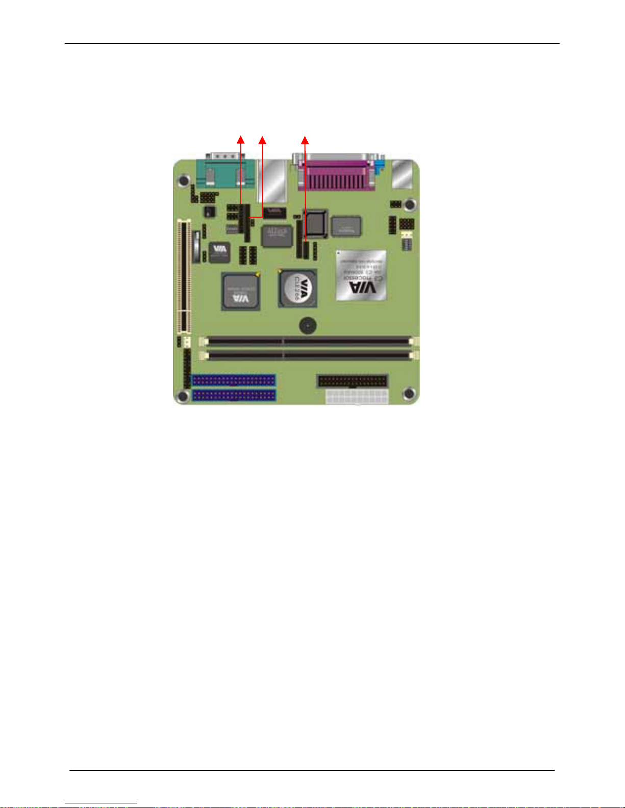
3.5.17 Optional DVO interface
The board supports DVO interface to support multimedia video input and
output.
Page 36
LV-666 User’s Manual
Attaching Connectors
36
Hardware Installation
3.6 Installing System Memory
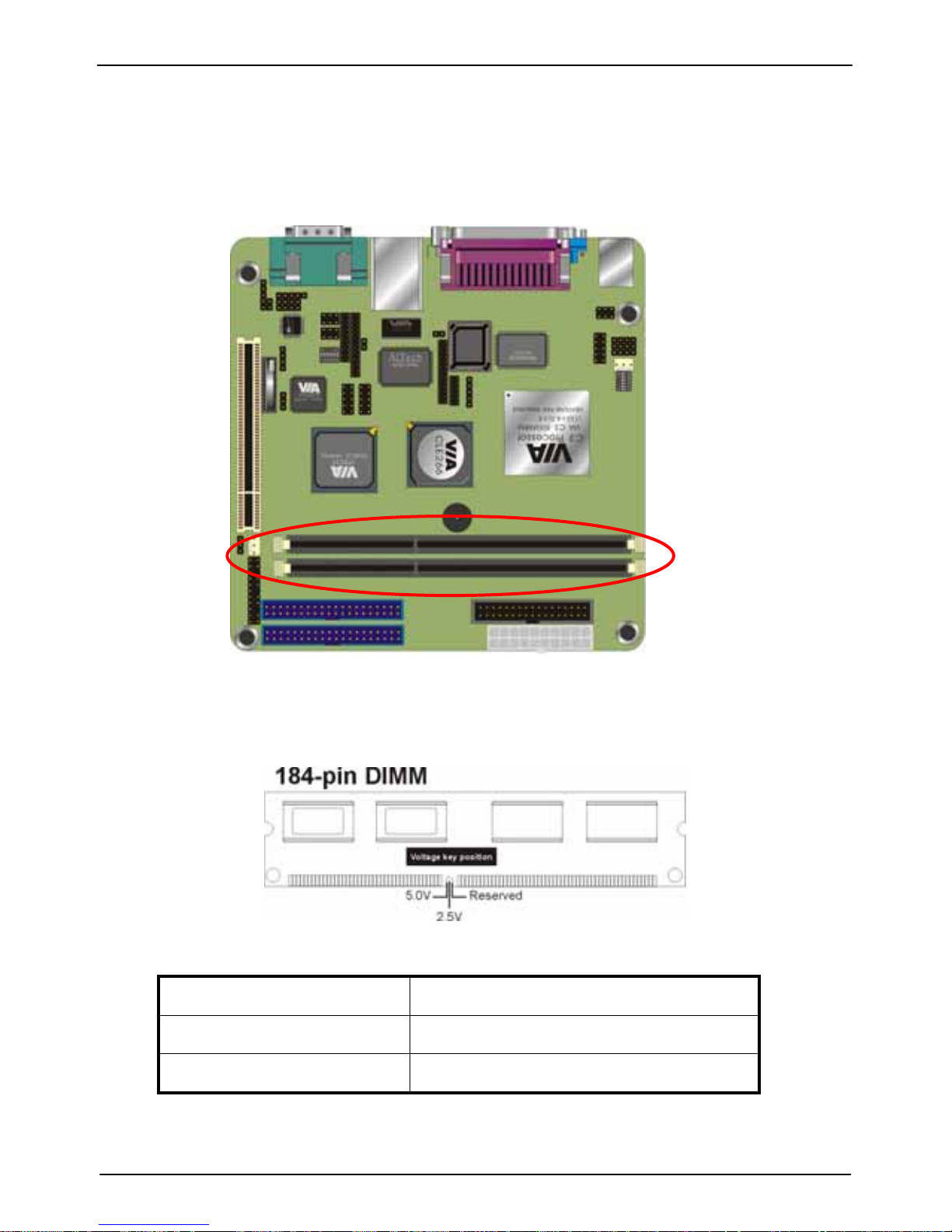
Maximum system memory supported by the motherboard is 2GB.The
motherboard has two DIMM Sockets. Memory can be installed using 184-pin DDR
SDRAM DIMM memory modules. These are no jumper settings required for the
memory size or type, which is automatically detected by the BIOS.
The motherboard support DDR200/266 SDRAM. If you install higher frequency
RAM module more than 266MHz, the system will force it to run under 266MHz.
Install the 184-pin DDR SDRAM modules in any combination as follows:
Bank 0 (DIMM1) 64MB/128MB/512MB/1GB
Bank 1 (DIMM2) 64MB/128MB/512MB/1GB
Total System Memory 64MB ~ 2GB
DIMM2
DIMM1
Page 37
LV-666 User’s Manual
Installing System Memory
37
Hardware Installation
3.7 CPU & CMOS Jumper Setting
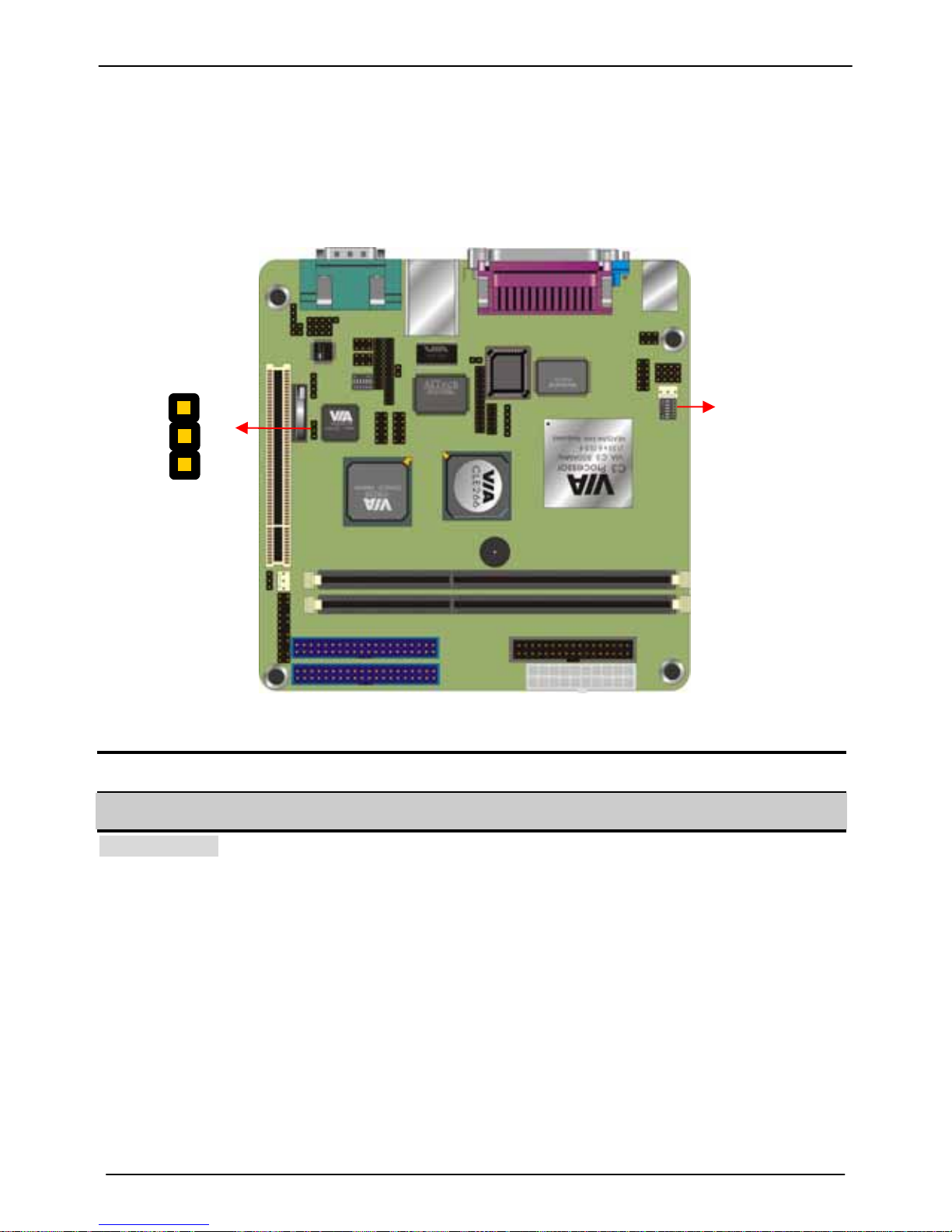
Refer to the following illustration and instructions to set the jumpers on your
motherboard.
Notice: the SW2 can let you configure the CPU ratio, but we have set done this
before the board is shipped, please do not attend to overclock, this may due to the
system unstable.
CLEAR_COMS1
SW2
CLEAR_CMOS1 Mode
1-2 Clear CMOS
2-3 Normal Operation
Default setting
You may need to clear the CMOS if your system cannot boot up because you
forgot your password, the CPU clock setup is incorrect, or the CMOS setting need
to reset to default values after the system BIOS has been updated.
Page 38

LV-666 User’s Manual
CPU & CMOS Jumper Setting
38
Hardware Installation
Please check the following ratio form of CPU clock ratio if your board runs the
wrong frequency of your order.
SW2
CPU RATIO 1 2 3 4 5
3.0x OFF ON ON ON ON
3.5x OFF ON OFF ON ON
4.0x ON OFF ON ON ON
4.5x ON OFF OFF ON ON
5.0x ON ON ON OFF ON
5.5x ON ON OFF ON ON
6.0x OFF OFF ON OFF ON
6.5x OFF OFF OFF OFF ON
7.0x OFF ON ON OFF ON
7.5x OFF ON OFF OFF ON
8.0x ON OFF ON OFF ON
8.5x ON OFF OFF OFF ON
9.0x ON ON ON ON ON
9.5x OFF OFF OFF ON ON
10.0x OFF OFF ON ON ON
10.5x OFF OFF OFF ON OFF
11.0x OFF ON ON ON OFF
11.5x OFF ON OFF ON OFF
12.0x ON OFF ON ON OFF
12.0x ON ON OFF OFF ON
12.5x ON OFF OFF ON OFF
13.0x ON ON ON OFF OFF
13.5x ON ON OFF ON OFF
14.0x OFF OFF ON OFF OFF
14.5x OFF OFF OFF OFF OFF
15.0x OFF ON ON OFF OFF
15.5x OFF ON OFF OFF OFF
16.0x ON OFF ON OFF OFF
Page 39
LV-666 User’s Manual
LVDS Module Setup Information
39
App
endix
Appendix A: LVDS Module Setup Information
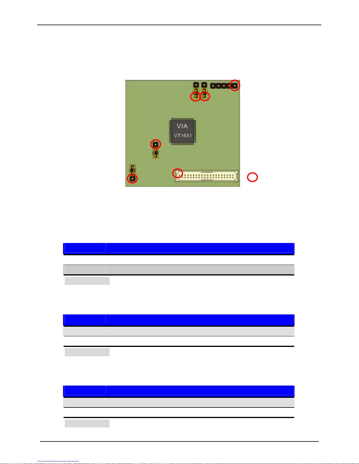
A.1: Layout
JP1
JP2
CN3
JP5
JP3
CN2
Pin-1
A.2 Jumper and Connector Reference
Jumper: JP1
Type: Onboard 3-pin Header
JP1 Mode
1-2 24-bit data in
2-3 12-bit data in
Default setting
Jumper: JP2
Type: Onboard 3-pin Header
JP2 Mode
1-2 Single-ended clock mode using CLKIN+ only
2-3 Select clock mode using CLKIN+ and CLKIN-
Default setting
Jumper: JP3
Type: Onboard 3-pin Header
JP2 Mode
1-2 Panel power input +5V
2-3 Panel power input +3.3V
Default setting
Page 40
P6F169 User’s Manual Appendix
LVDS Module Setup Information
40
Jumper: JP5
Type: Onboard 3-pin Header
JP2 Mode
1-2 12-bit input with 24-bit RGB data input/output
2-3 Two 12-bit input with 48-bit RGB data input/output
Default setting
Connector: CN3
Type: 5-pin header inverter connector
Pin 1 2 3 4 5
Assignment +12V GND GND GND +5V
Connector: CN2
Type: onboard 40-pin connector for LVDS connector
Pin Signal Pin Signal
2 PVDD 1 PVDD
4 GND 3 GND
6 ATX0- 5 BTX0-
8 ATX0+ 7 BTX0+
10 GND 9 GND
12 ATX1- 11 BTX114 ATX1+ 13 BTX1+
16 GND 15 GND
18 ATX2- 17 BTX220 ATX2+ 19 BTX2+
22 GND 21 GND
24 ATX3- 23 BTXCK26 ATX3+ 25 BTXCK+
28 GND 27 GND
30 ATXCK- 29 BTX332 ATXCK+ 31 BTX3+
34 GND 33 GND
36 N/C 35 N/C
38 N/C 37 N/C
40 N/C 39 N/C
Page 41

P6F169 User’s Manual Appendix
LVDS Module Setup Information
41
A.3 BIOS Panel Type Table
Panel ID Resolution Channel Dithering
0 640x480 1 Enable
1 800x600 1 Enable
2 1024x768 1 Enable
3 1280x768 1 Enable
4 1280x1024 2 Enable
5 1400x1050 2 Enable
6 1600x1200 2 Enable
7 1280x800 1 Enable
8 800x480 1 Enable
9 1024x768 2 Enable
A 1024x768 1 Disable
B 1024x768 2 Disable
C 1280x768 1 Disable
D 1280x1024 2 Disable
E 1400x1050 2 Disable
F 1600x1200 2 Disable
Dithering Enable is for 18-bit panel and Disable is for 24-bit panel
Page 42

LV-666 User’s Manual
Contact Information
42
Contact Information
Contact Information
Any advice or comment about our products and service, or anything we can help you please don’t
hesitate to contact with us. We will do our best to support you for your products, projects and business.
COMMELL IPC Division
Taiwan Commate Computer, Inc.
COMMELL
www.commell.com.tw
Your Embedded Applied Computer Partner
Address
8F, No. 94, Sec. 1, Shin Tai Wu Rd., Shi Chih
Taipei Hsien, Taiwan
TEL +886-2-26963909
FAX +886-2-26963911
Website
http://www.commell.com.tw
E-Mail [email protected] (General Information)
[email protected] (Technical Support)
 Loading...