

Page 1

User’s Manual
HE-840
Half-size ISA-bus Embedded 5x86-133 CPU Card
with AMD Am5x86-133 MHz CPU, 8 MB EDO DRAM,
Flat Panel / CRT SVGA, 10/100 Mbps LAN Interfaces,
Four Serial Ports and DiskOnChip Socket
Page 2

HE-840
User’s Manual
Version 1.0
Copyright
are reserved. The information in this document is subject to change without prior
notice to make improvements to the products.
This document contains proprietary information and protected by copyright. No
part of this document may be reproduced, copied, or translated in any form or
any means without prior written permission of the manufacturer.
©
2002,. All rights reserved. This document is copyrighted and all rights
All trademarks and/or registered trademarks contains in this document are
property of their respective owners.
S/N: OPMHE840-10
Page 3

Packing List
Hardware
HE-840VL CPU Card .......................................................X 1
Cable Kit
IDE Flat Cable.................................................................. X 1
FDD Cable .......................................................................X 1
DB25 LPT Port Cable....................................................... X 1
Dual DB9 COM Port Cable............................................... X 2
Printed Matter and Software
User’s Manual .................................................................. X 1
Driver Disk Kit ..................................................................X 1
FS-975 User’s Manual
3
Page 4

Table of Contents
Chapter 1. Introduction.................................................. 2
1.1 Product Overview......................................................... 2
1.2 Specifications ............................................................... 3
1.3 Component Placement................................................. 6
Chapter 2.
2.1 Connectors and Jumpers Location ............................... 7
2.2 Jumpers Settings ......................................................... 8
2.3 Connectors................................................................... 9
2.4 Switches & Indicators Pin Assignment........................ 10
2.5 LCD Connector Pin Assignment ................................. 11
Chapter 3. BIOS Setup ................................................ 12
Chapter 4.
Hardware Setup............................................. 7
Driver installation ........................................ 13
Page 5

Chapter 1. Introduction
1.1 Product Overview
The HE-840 Single Board Computer is an all-in-one industrial half-size
ISA-bus CPU card. It integrated with embedded AMD Am5x86-133 CPU and
8 MB of EDO DRAM, PCI-based flat panel / CRT SVGA, 10/100 Mbps Fast
Ethernet interfaces, 4 serial ports and DiskOnChip embedded flash disk
socket.
Embedded 486 Level CPU
AMD Am5x86-133 CPU provides the embedded platform with 486DX5
architecture at 133 MHz of working frequency.
Integrated System Memory
Onboard 8 MB of EDO DRAM and one 72-pin SIMM expansive slot supports
additional 32 MB of memory.
.
Flat Panel SVGA Interface
PCI-based C&T 69000 flat panel / CRT SVGA with 2 MB of on-die video
memory supports flat panel and CRT display.
Fast Ethernet Interface
PCI-based 10/100 Mbps Fast Ethernet interface, 10Base-T/100Base-TX,
auto-switching Fast Ethernet, full duplex, IEEE 802.3U compliant.
Four Serial Ports
Four serial ports include three RS-232C and one jumper selectable
RS-232C/485 ports with high speed 16C550 compatible UART with 16 byte
FIFO and BIOS enabled/disabled.
DiskOnChip Interface
32-pin M-systems DiskOnChip 2000 socket supports 2 to 288 MB embedded
solid state of flash disk.
2
HE-840 User’s Manual
Page 6

1.2 Specifications
General Specification
! CPU (installed) : AMD Am5x86-133 embedded CPU with jumper
selectable speed (75/100/133) for the low power, low temperature
operation
!
Chipset : ALi 1487 / 1489
! BIOS
! Green Function : power saving options supported in BIOS. DOZE /
STANDBY / SUSPEND modes
! L2 Cache : 128 KB pipelined Burst
!
DRAM Memory : 8 MB up to 40MB EDO DRAM, with onboard 8 MB of
EDO DRAM and one 72-pin single sided SIMM slot supports up to 32 MB
of expansive EDO DRAM
! Bus Interface : ISA and PC/104
! Data Bus : 16-bit
! Bus Speed : ISA, PC/104 - 8.3MHz
!
DMA Channels : 7
!
Interrupt Levels : 15
! PCI Enhanced IDE
Supports IDE PIO mode up to Mode 4 and DMA mode 2.
! Watchdog Timer : generates an NMI or system RESET when your
application loses control over the system. The timer interval is: 1, 2, 10,
20, 110 and 220 seconds.
!
Real-time Clock : Benchmarq bq3287AMT (Dallas DS-12B887
compatible) RTC. CMOS data backup of BIOS setup and BIOS default.
! Keyboard and Mouse Connectors:
- External 6-pin mini DIN for PS/2 Mouse on bracket
- External 6-pin mini DIN for PS/2 Keyboard on bracket
- Onboard 5-pin box header connector for AT keyboard
: AWARD PCI/ISA PnP system BIOS
: supports two ports and up to four ATAPI devices.
HE-840 User’s Manual
3
Page 7
High Speed Multi-I/O
! Chipset : ALi 5113
!
! Floppy Disk Drive interface : up to two floppy drives, 5.25" (360 KB or
!
Serial Ports : three high speed RS-232C ports (COM1, COM3, COM4)
and one jumper selectable RS-232C/485 port (COM2). All with high
speed 16C550 compatible UART with 16 byte FIFO and BIOS
enabled/disabled.
1.2 MB) and 3.5" (720 KB, 1.44MB or 2.88 MB) , BIOS
enabled/disabled.
Bi-directional Parallel Port : SPP, EPP and ECP mode, BIOS
enabled/disabled.
Flat Panel / CRT SVGA Interface
!
! BIOS : combined with system BIOS
! Display Type : CRT, TFT, DSTN, SSTN, EL, Plasma Quarter VGA
! Display Mode :
! Connectors :
Chipset : PCI-based C&T69000 with 2 MB of on-die video memory
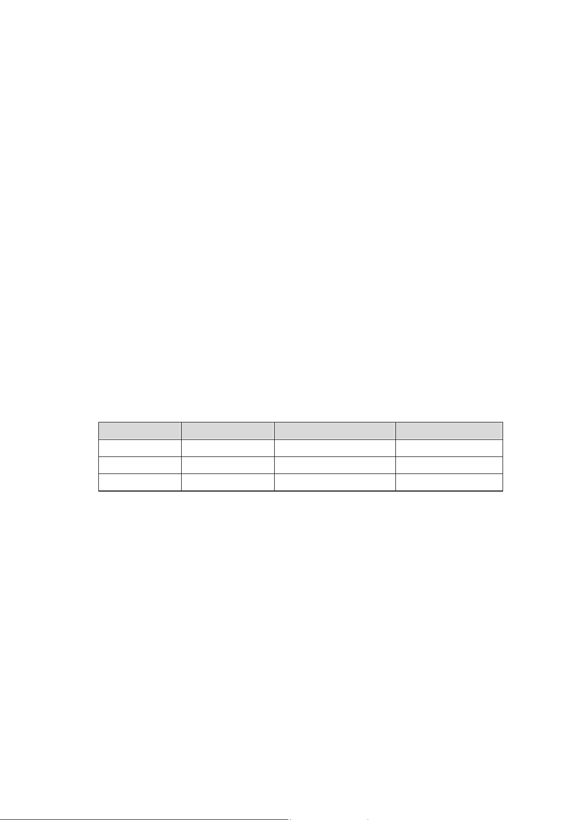
VGA Type Resolution Color Refresh Rate
SVGA 800 x 600 True Color / 24 bpp 60/75/85 Hz
XGA 1024 x 768 High Color / 16 bpp 60/75/85 Hz
SXGA 1280 x 1024 256 Color / 8 bpp 60 Hz
- onboard 50-pin box header for Flat Panel display
- external 15-pin D-sub connector on bracket for CRT
Flash Disk DiskOnChip 2000
! Package : Single Chip Flash Disk in 32-pin DIP JEDEC
! Capacity : up to 288 MB
!
! Memory Window : 8 KByte
4
Data Reliability : ECC/EDC error correction
HE-840 User’s Manual
Page 8

Environmental and Power
! Power Requirement : +5V (4.75~5.25 V) @ 1.8A typical (onboard
CPU and EDORAM), +/-12 V
! Board Dimension : 185mm x 122mm (L x W)
!
!
Board Weight : 0.24Kg
Operating Temperature : 0 to 60℃ (32 to 140℉)
HE-840 User’s Manual
5
Page 9
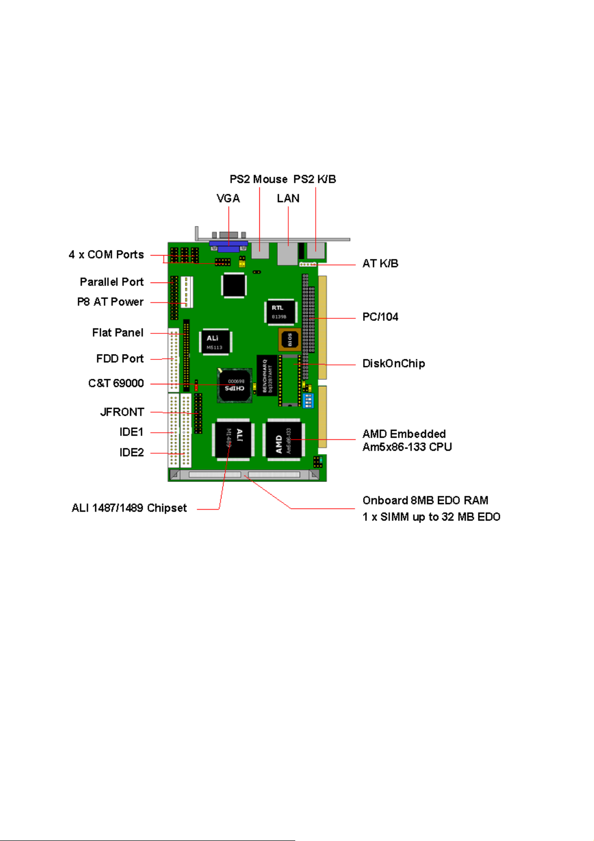
1.3 Component Placement
6
HE-840 User’s Manual
Page 10
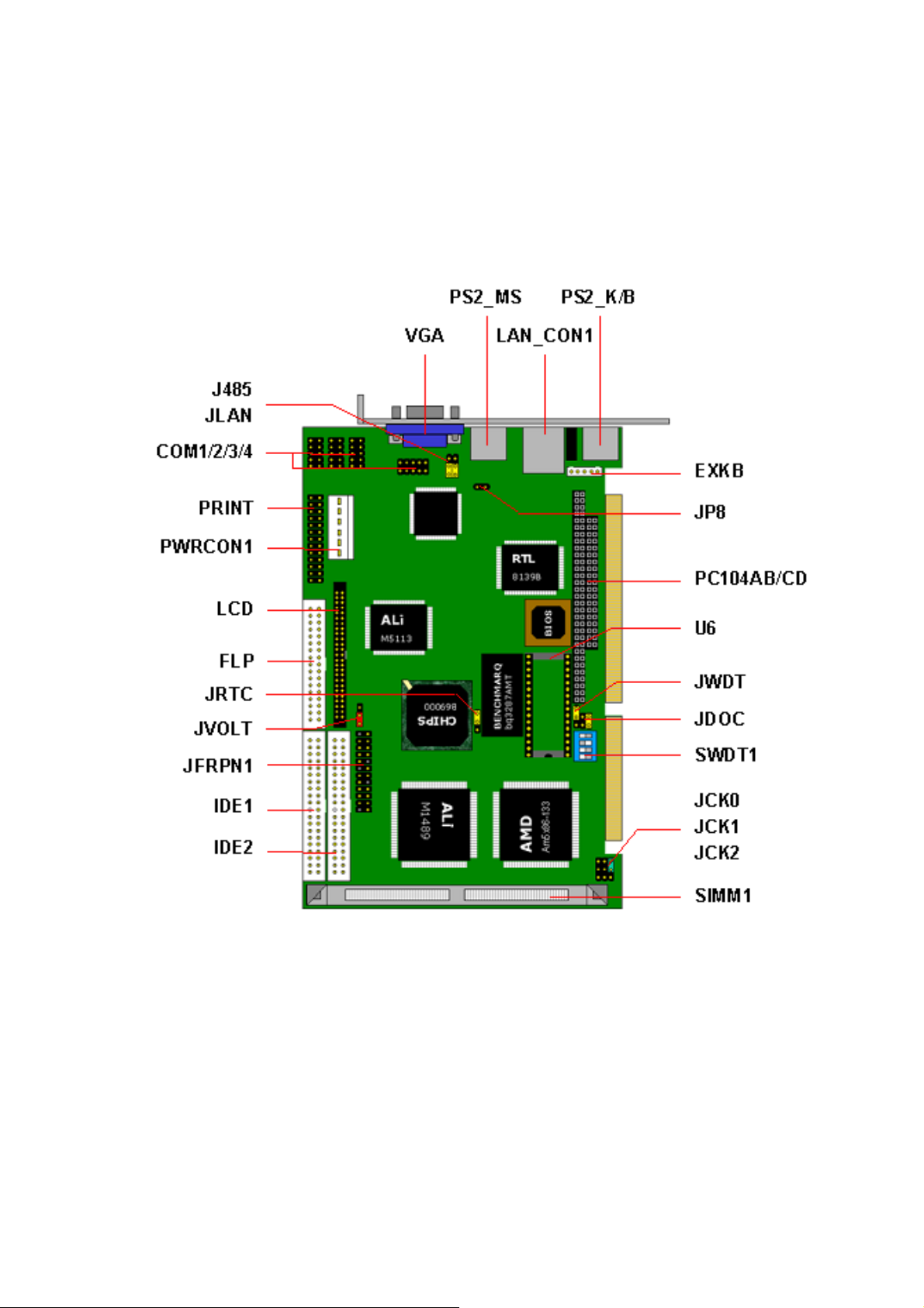
Chapter 2. Hardware Setup
2.1 Connectors and Jumpers Location
HE-840 User’s Manual
7
Page 11
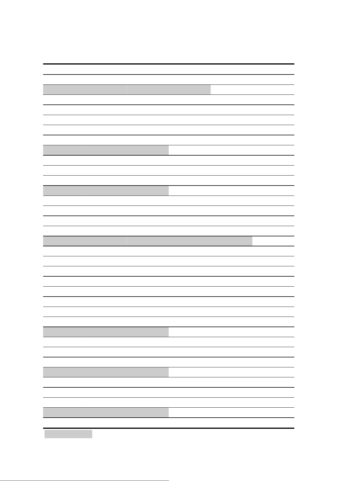
2.2 Jumpers Settings
JCK0/1/2 CPU Speed
JCK0 JCK1 JCK2 Speed
OFF OFF 2-3 133 MHz
OFF OFF 1-2 100 MHz
2-3 2-3 2-3 75 MHz
JRTC RTC/COMS Operation
1-2 Clear COMS
2-3 Normal Operation
JWDT Watchdog Timer Setting
1-2 IO Check
2-3 Reset
OFF Disable
SWDT1 Watchdog Timer Timeout Value Setting
1 2 3 4 Timeout (Seconds)
OFF OFF ON OFF 1
OFF OFF ON ON 2
OFF ON ON OFF 10
OFF ON ON ON 20
ON OFF OFF OFF 110
ON OFF OFF ON 220
JDOC DiskOnChip Address Setting
1-2 D000h
2-3 D800h
OFF Disable
J485 COM2 RS-232C/485 Mode Selection
1-2 RS-232C
2-3 RS-485
JVOLT Flat Panel VCC Voltage Setting
1-2 5 Volt
2-3 3.3 Volt
Default Setting
8
HE-840 User’s Manual
Page 12

2.3 Connectors
IDE1 40-pin Primary IDE Port
IDE2 40-pin Secondary IDE Port
FLP 34-pin FDD Port
PRINT 26-pin Parallel Port
LCD 50-pin Flat Panel Connector
JP8 2-pin RS485 COM2 Serial Port
EXKB 5-pin AT Keyboard Connector
PWRCON1 6-pin P8 AT Power Connector
COM1 10-pin COM1 RS-232C Serial Port
COM2 10-pin COM2 RS-232C Serial Port
COM3 10-pin COM3 RS-232C Serial Port
COM4 10-pin COM4 RS-232C Serial Port
SIMM1 72-pin SIMM Slot
U6 32-pin DiskOnChip Socket
PC104AB/CD PC/104 Connector
JFRPN1 Switched and Indicators
VGA DB15 Female VGA Port on Bracket
PS2_K/B 6-pin MiniDIN PS/2 Keyboard on Bracket
PS2_MS 6-pin MiniDIN PS/2 Mouse on Bracket
LAN_CON1 RJ45 LAN Port on Bracket
HE-840 User’s Manual
9
Page 13
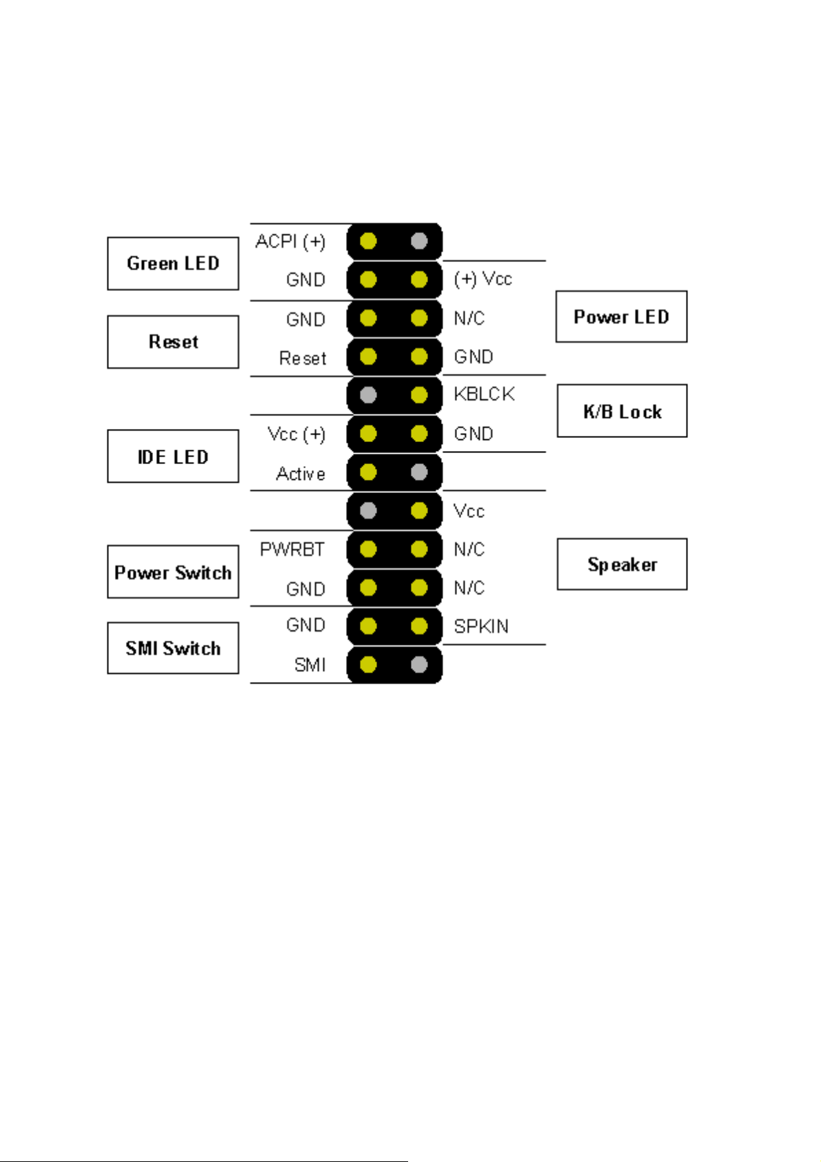
2.4 Switches & Indicators Pin Assignment
10
HE-840 User’s Manual
Page 14

2.5 LCD Connector Pin Assignment
Connector : LCD
Type : onboard 50-pin box header
Pin Signal Pin Signal
1 +12V 2 +12V
3 GND 4 GND
5 VCC (LCD) 6 ENAVDD
7 ENAVEE 8 GND
9 P0 10 P1
11 P2 12 P3
13 P4 14 P5
15 P6 16 P7
17 P8 18 P9
19 P10 20 P11
21 P12 22 P13
23 P14 24 P15
25 P16 26 P17
27 P18 28 P19
29 P20 30 P21
31 P22 32 P23
33 P24 34 P25
35 SHFCLK 36 FLM
37 M 38 LP
39 GND 40 ENABKL
41 P26 42 P27
43 P28 44 P29
45 P30 46 P31
47 P32 48 P33
49 P34 50 P35
HE-840 User’s Manual
11
Page 15

Chapter 3. BIOS Setup
The single board computer uses the Award BIOS for the system configuration.
The Award BIOS in the single board computer is a customized version of the
industrial standard BIOS for IBM PC AT-compatible computers. It supports
Intel x86 and compatible CPU architecture based processors and computers.
The BIOS provides critical low-level support for the system central processing,
memory and I/O sub-systems.
The BIOS setup program of the single board computer let the customers
modify the basic configuration setting. The settings are stored in a dedicated
battery-backed memory, NVRAM, retains the information when the power is
turned off. If the battery runs out of the power, then the settings of BIOS will
come back to the default setting.
The BIOS section of the manual is subject to change without notice and is
provided here for reference purpose only. The settings and configurations of
the BIOS are current at the time of print, and therefore they may not be
exactly the same as that displayed on your screen.
12
HE-840 User’s Manual
Page 16

Chapter 4. Driver installation
You can use the auto run menu of this CD Disc. The screen shows as you
BIOS ID then please choose your preferred mode of this installation program:
Detect and select your motherboard type automatically.
Select motherboard type on your own manually.
The CD Driver Disk for Single Board Computer’s Chipset Setup includes
drivers for IDE, VGA, and LAN interfaces.
HE-840 User’s Manual
13
 Loading...