

Page 1
ETB-ITX1
ETX Baseboard
User’s Manual
Edition 1.0
2006/5/30
Page 2

ETB-ITX1 User’s Manual
2
Copyright
Copyright 2006 all rights reserved. This document is copyrighted and all rights are
reserved. The information in this document is subject to change without prior notice to
make improvements to the products.
This document contains proprietary informat ion and protected by copyright. No part of
this document may be reproduced, copied, or translated in any form or any means
without prior written permission of the manufacturer.
All trademarks and/or registered trademarks contains in this document are property of
their respective owners.
Disclaimer
The company shall not be liable for any incidental or consequential dam ages resulting
from the performance or use of this product.
The company does not issue a warranty of any kind, express or implied, including
without limitation implied warranties of merchantability or fitness for a particular purpose.
The company has the right to revise the manual or include changes in the specifications
of the product described within it at any time without notice and without obligation to
notify any person of such revision or changes.
Trademark
All trademarks are the property of their respective holders.
Any questions please visit our website at TUhttp://www.commell.com.twUT
Page 3
ETB-ITX1 User’s Manual
3
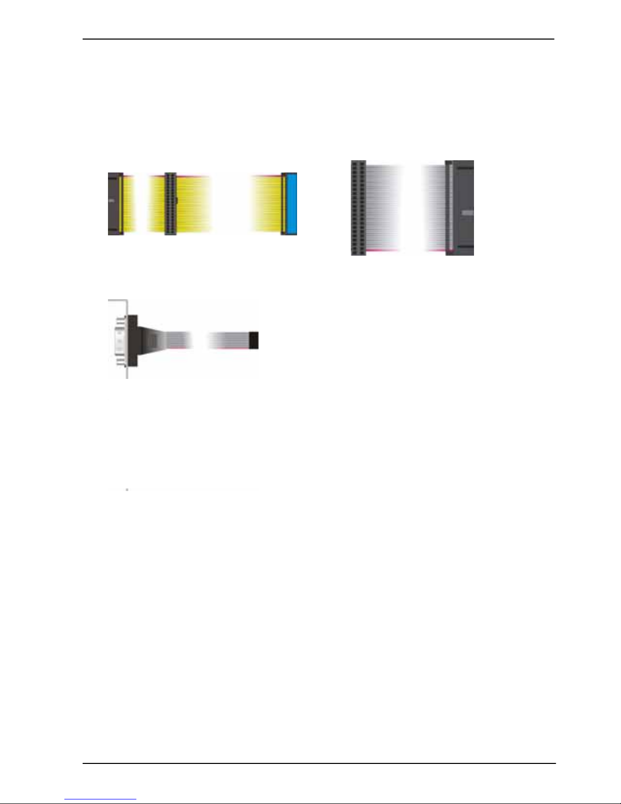
COM port Cable x 1
Packing List:
Please check the package content before you starting using the board.
Hardware:
ETB-ITX1 baseboard x 1
Cable Kit:
ATA100 IDE Cable x1
Printed Matters:
User’s Manual x 1
44-pin ATA33 IDE Cable x 1
Page 4

ETB-ITX1 User’s Manual
4
Index
Chapter 1 <Introduction>................................................................................7
1.1 <Product Overview>............................................................................7
1.2 <Product Specification>......................................................................8
1.3 <Mechanical Drawing>......................................................................10
1.4 <Block Diagram>...............................................................................11
Chapter 2 <Hardware Setup>........................................................................13
2.1 <Connector Location>.......................................................................13
2.2 <Jumper Location & Reference> ......................................................14
2.3 <Connector Reference>....................................................................15
2.3.1 <Internal Connectors>...........................................................15
2.3.2 <External Connectors>..........................................................15
2.4 <Enhanced IDE Interface>................................................................16
2.5 <Ethernet Interface> .........................................................................17
2.6 <Display Interface> ...........................................................................18
2.6.1 <Analog Display> ..................................................................18
2.6.2 <Digital Display>....................................................................19
2.7 <Audio Interface>..............................................................................22
2.8 <Serial Port Jumper Setting>…...……………………………23
2.9 <GPIO Interface>………………………………………………………...25
2.10 <Power Supply>..............................................................................26
2.10.1 <Power Input>.....................................................................26
2.11 <Switch and Indicator>....................................................................27
Appendix A <I/O Port Pin Assignment>.......................................................29
A.1 <IDE Port>........................................................................................29
A.2 <IrDA Port>.......................................................................................31
A.3 <Serial Port>.....................................................................................31
A.4 <VGA Port>.......................................................................................32
A.5 <LAN Port>.......................................................................................32
A.6< LPT Port >……………………………………………… ……………….33
Page 5

ETB-ITX1 User’s Manual
5
Appendix B <Flash BIOS>……………………………………………………….34
B.1 <Flash Tool>.....................................................................................34
B.2 <Flash BIOS Procedure> .................................................................34
Contact Information..........................................................................................35
Page 6

ETB-ITX1 User’s Manual
6
(This Page is Left for Blank)
Page 7

ETB-ITX1 User’s Manual Introduction
Product Overview
7
Chapter 1 <Introduction>
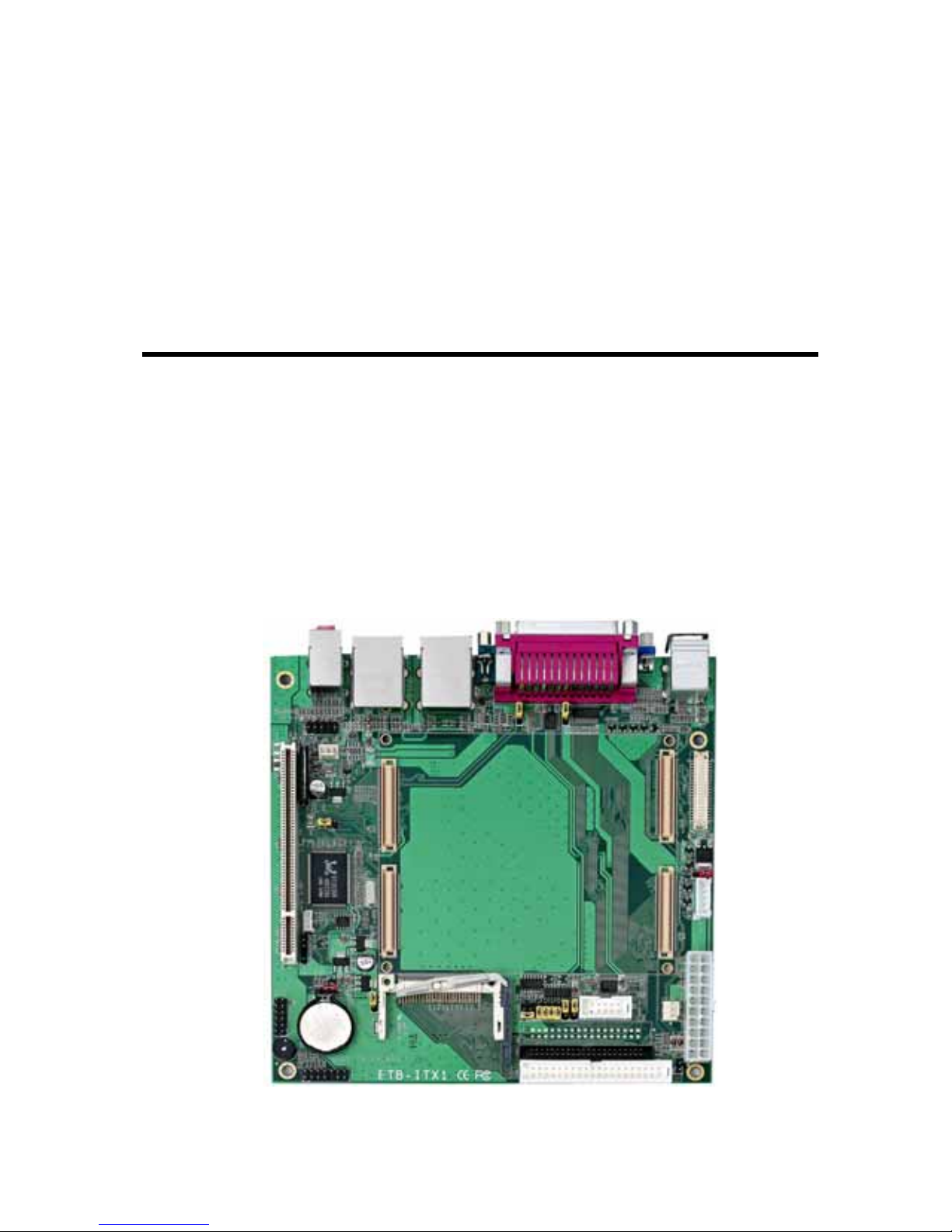
1.1 <Product Overview>
ETB-ITX1 is the ETX Module baseboard provide VGA, Audio, PCI slot , LVDS, Dual
LAN, CF, IDE, Serial Port and LPT Port.
All in One multimedia solution
The baseboard provides 18/24-bit dual chan nel LVDS connector and 2 channels Audio,
to meet the very requirement of the multimedia application.
Flexible Extension Interface
The baseboard provides one PCI slot supports up to 2 PCI devices.
Page 8

ETB-ITX1 User’s Manual Introduction
Product Specification
8
1.2 <Product Specification>
General Specification
Form Factor Mini-ITX Baseboard
Real Time Clock RTC with lithium battery
Enhanced IDE Provide UltraDMA100 IDE interface supports up to 4 ATAPI devices
One 40-pin and one 44-pin IDE
One Compact Flash Type II socket
Multi-I/O Port
Serial Port One external DB9 male connector on rear I/O panel and one internal
RS-232/422/485 serial port
USB Port Four external Hi-Speed USB 2.0 ports with 480Mbps of transfer rate
on rear I/O panel
Parallel Port One external DB25 female connector on rear I/O panel
IrDA Port One IrDA compliant Infrared interface supports SIR
K/B & Mouse External PS/2 keyboard and mouse ports on rear I/O panel
GPIO One 12-pin Digital I/O connector with 8-bit programmable I/O interface
Fan Two fan connectors
VGA Display Interface
Connector External DB15 female connector on rear I/O panel
Onboard 40-pin LVDS connector
Page 9

ETB-ITX1 User’s Manual Introduction
Product Specification
9
Ethernet Interface
Chipset Realtek RTL8100B
Type 10/100 Base-T
auto-switching Fast Ethernet
Full duplex, IEEE802.3U compliant
Connector Two External RJ45 connectors with LED on rear I/O panel
Audio Interface
Interface 2 channels sound output
Connector External Audio phone jack for Line-out, Line-in, MIC-in.
Onboard audio connector with pin header (built-in amplifier for speaker
out)
Expansive Interface
PCI One PCI slot for supports up to 2 PCI bus master PCI devices.
(32-bit, 33MHz)
Power supply: +3.3V, +5V
Power and Environment
Power
Requirement
Standard ATX Power connector
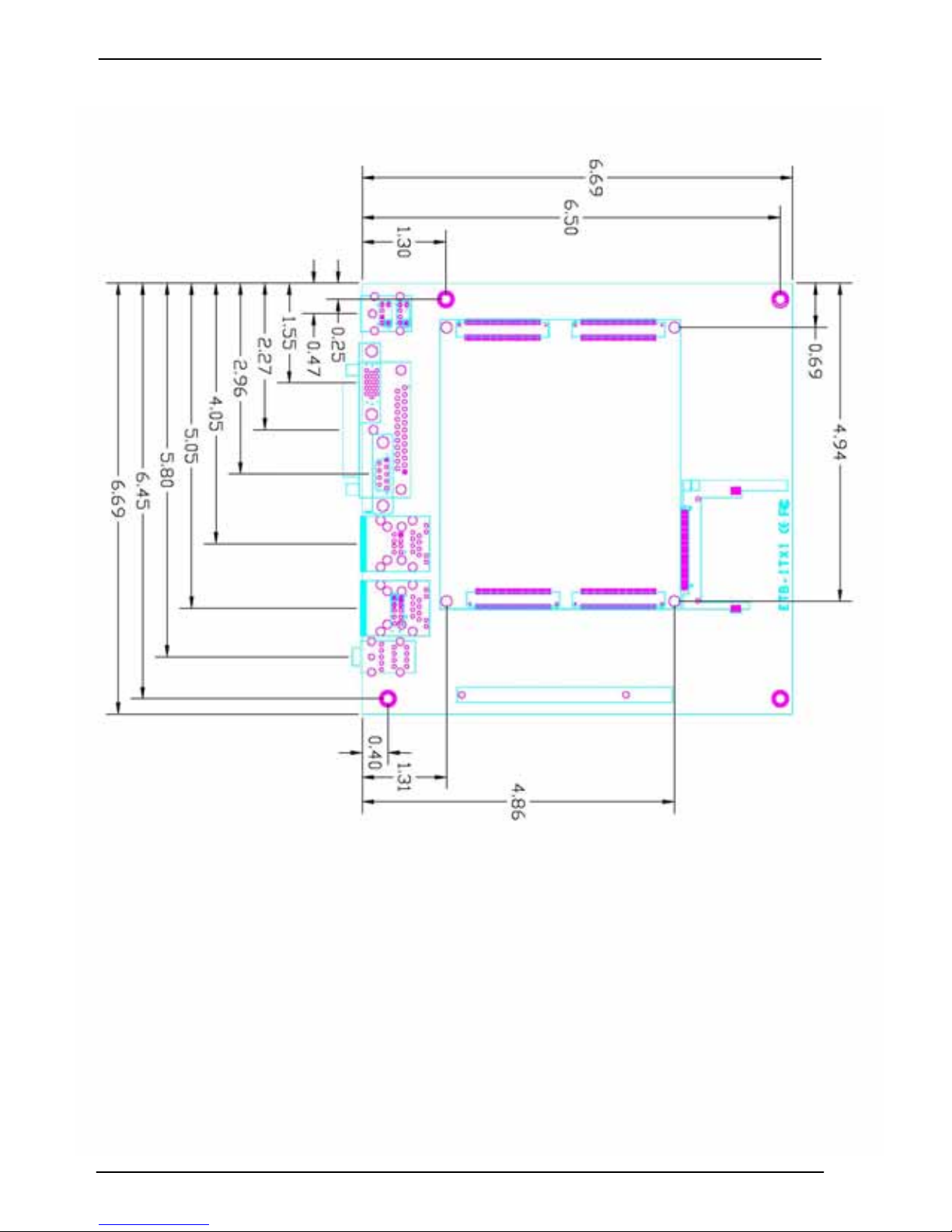
Dimension 170(L) x 170 (H) mm
Temperature Operating within 0 ~ 60P
o
P
C (32 ~ 140P
o
P
F)
Storage within -20 ~ 85P
o
P
C (-4 ~ 185P
o
P
F)
Ordering Code
ETB-ITX1 ETX Module baseboard
The specifications may be different as the actual production.
For further product information please visit the website at TUhttp://www.commell.com.tw
UT
Page 10
ETB-ITX1 User’s Manual Introduction
Mechanical Drawing
10
1.3 <Mechanical Drawing>
Page 11
ETB-ITX1 User’s Manual Introduction
Block Diagram
11
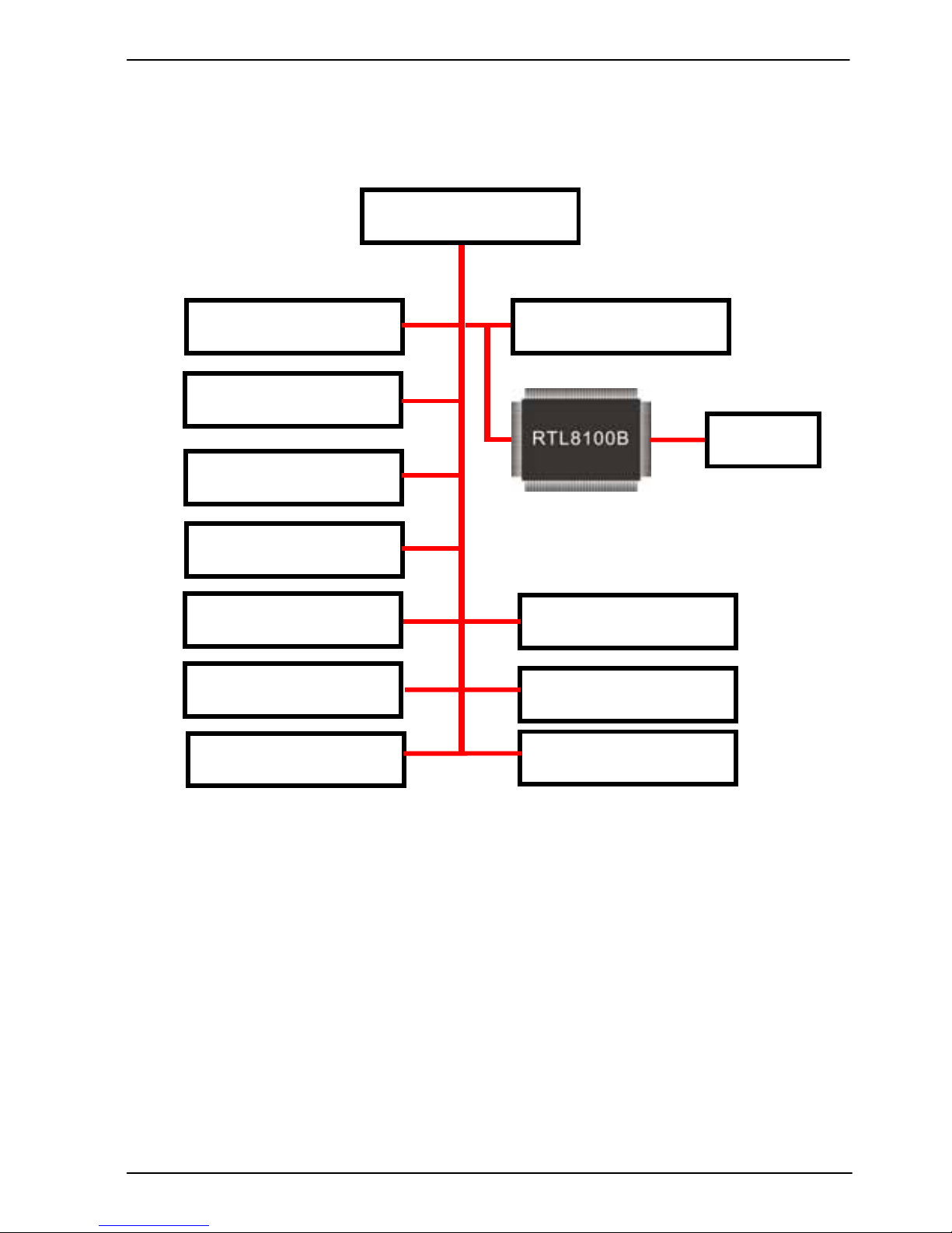
1.4 <Block Diagram>
LVDS
4 x USB2.0 ports
UltraDMA33/66/100 IDE
2 x Serial ports
8-bit GPIO
IrDA
ETX Module
CRT
1 x PCI Slot
LPT Port
KB & MS
10/100 RJ45
RJ45
Page 12

ETB-ITX1 User’s Manual
12
(This Page is Left for Blank
Page 13

ETB-ITX1 User’s Manual Hardware Setup
Connector Location
13
Chapter 2 <Hardware Setup>
2.1 <Connector Location>
ATX1
CN_INV
CF
JFRNT
CN_DIO
CN_AUDIO
CN_IR
PCI
CN_LVDS
IDE1/2
CN_WOL
SYSFAN2
SYSFAN1
CN_COM1
LPT
VGA COM
AUDIO
PS/2
USB1/2/3/4
LAN1/2
Page 14

ETB-ITX1 User’s Manual Hardware Setup
Jumper Location & Reference
14
2.2 <Jumper Location & Reference>
Jumper Function
JVLCD Panel Voltage Setting
JDOM IDE Pin-20 voltage setting
JC3/4 Setting CN_COM1 power provide
JCSEL1 Setting RS232/422/485
JCSEL2 Setting RS232/422/485
JCFSEL Setting CF Master/slave
JRTC CMOS Operating/Clear Setting
JLAN Enable/disable LAN
JVLCD
JDOM
JRTC
JLAN
JCSEL2
JCSEL1
JCFSEL
JC3/4
Page 15

ETB-ITX1 User’s Manual Hardware Setup
Connector Reference
15
2.3 <Connector Reference>
2.3.1 <Internal Connectors>
Connector Function Remark
IDE1 40-pin IDE connector Standard
IDE2 44-pin IDE connector Slim
CF Compact Flash Type II socket Standard
ATX1 20-pin ATX power input connector Standard
CN_AUDIO 5 x 2-pin audio connector Standard
CN_DIO 6 x 2-pin digital I/O connector Standard
CN_WOL 3-pin wake on LAN connector Standard
SYSFAN1/2 3-pin system cooler fan connector Standard
CN_LVDS 20 x 2-pin LVDS connector Standard
CN_INV 5-pin LCD inverter connector Standard
CN_IR 5-pin IrDA connector Standard
CN_COM1 5 x 2-pin COM2 connector Standard
JFRNT 14-pin front panel switch/indicator connector Standard
PCI Standard 32bit PCI slot Slim
2.3.2 <External Connectors>
Connector Function Remark
PS2 PS/2 keyboard connector Standard
LPT DB25 female connector Standard
VGA DB15 analog VGA connector Standard
COM DB9 Serial port connector Standard
USB_RJ451/2 Dual USB and RJ45 LAN connector Standard
AUDIO Audio phone jack Standard
Page 16

ETB-ITX1 User’s Manual Hardware Setup
Enhanced IDE Interface
16
2.4 <Enhanced IDE Interface>
The baseboard has two UltraDMA33/66/100 IDE interface to support up to 4 ATAPI
devices, with jumper JDOM for Disk on module.
The board also provides a Compact Flash Type II socket with jumper (JCFSEL)
selectable Slave/Master mode on secondary IDE channel.
Jumper: JCFSEL
Type: onboard 3-pin header
JCFSEL Mode
1-2 Master
2-3 Slave
Default setting
Jumper: JDOM
Type: onboard 2-pin header
JDOM Mode
1-2 Short
1-2 Open (default)
Default setting
JDOM
CF
JCFSEL
Page 17

ETB-ITX1 User’s Manual Hardware Setup
Ethernet Interface
17
2.5 <Ethernet Interface>
The baseboard provides two RJ45 connectors of 10/100Base-T, with IEEE802.3
compliance one for ETX module(LAN1). The other for integrates Realt ek RTL8100B
(LAN2)Ethernet controller.
LAN1 LAN2
Page 18

ETB-ITX1 User’s Manual Hardware Setup
Display Interface
18
2.6 <Display Interface>
The baseboard provides one DB15 connector on real external I/O port, and one 40-pin
LVDS interface with 5-pin LCD backlight inverter connector.
2.6.1 <Analog Display>
Please connect your CRT or LCD monitor with DB15 male connector to the onboard
DB15 female connector on rear I/O port.
VGA
Page 19

ETB-ITX1 User’s Manual Hardware Setup
Display Interface
19
2.6.2 <Digital Display>
The baseboard provides one 40-pin LVDS connector for 18/24-bit single/dual channel
panels, with one LCD backlight inverter connector and one jumper for panel voltage
setting.
CN_LVDS
1 2
39 40
1
5
CN_INV
1
3
JVLCD
Page 20

ETB-ITX1 User’s Manual Hardware Setup
Display Interface
20
Connector: CN_INV Connector: JVLCD
Type: 5-pin LVDS Power Header Type: 3-pin Power select Header
Connector model: JST B5B-XH-A
Pin Description Pin Description
1 +12V 1 VCC(5V)
2 GND 2 LCDVCC
3 GND 3 VCC3(3.3)
4 GND
5 ENABKL
Connector: CN_LVDS
Type: 40-pin connector
Connector model: HIROSE DF13-40DP-1.25V
Pin Signal Pin Signal
2 LCDVCC 1 LCDVCC
4 GND 3 GND
6 ATX0- 5 BTX0-
8 ATX0+ 7 BTX0+
10 GND 9 GND
12 ATX1- 11 BTX114 ATX1+ 13 BTX1+
16 GND 15 GND
18 ATX2- 17 BTX220 ATX2+ 19 BTX2+
22 GND 21 GND
24 ACLK- 23 BTX326 ACLK+ 25 BTX3+
28 GND 27 GND
30 ATX3- 29 BCLK32 ATX3+ 31 BCLK+
34 GND 33 GND
36 N/C 35 N/C
38 N/C 37 N/C
40 N/C 39 N/C
Page 21

ETB-ITX1 User’s Manual Hardware Setup
Display Interface
21
To setup the LCD, you need the component below:
1. A panel with LVDS interfaces.
2. An inverter for panel’s backlight power.
3. A LCD cable and an inverter cable.
For the cables, please follow the pin assignment of the conne ctor to make a c able, becaus e
every panel has its own pin assignment, so we do not pro vide a standard cable; ple ase find
a local cable manufacture to make cables.
LCD Installation Guide:
1. Preparing the EXB-ITX1, LCD panel and the backlight inverter.
2. Please check the datasheet of the panel to see the voltage of the panel, and set the
jumper JVLCD to +5V or +3.3V.
3. You would need a LVDS type cable.
4. To connect all of the devices well.
For sample illustrator only
Panel side
Board side
Page 22

ETB-ITX1 User’s Manual Hardware Setup
Audio Interface
22
2.7 <Audio Interface>
The baseboard provide internal Audio connector and Phone jack on rear I/O.
Connector: CN_AUDIO
Type: 10-pin (2 x 5) 2.54-pitch header
Pin Description Pin Description
1 Line – Right 2 Ground
3 Line – Left 4 MIC
5 N/C 6 Ground
7 N/C 8 Line Out – Left
9 Line Out – Right 10 Ground
CN_AUDIO
1
Rear I/O phone jacks
2
9
10
Page 23

ETB-ITX1 User’s Manual Hardware Setup
Serial Port Jumper Setting
23
2.8 <Serial Port Jumper Setting >
The board provides two RS232 serial ports, with jumper selectable +5V/+12V output
and RS422/485 for CN_COM1.
Jumper: JC3/4
Type: onboard 6-pin header
Pin Description Pin Description
1 +5V 2 +12V
3 CN_COM1 pin1 4 CN_COM1 pin9
5 DCD- 6 RI-
5 6
1 2
JC3/4
JCSEL2
JCSEL1
Page 24

ETB-ITX1 User’s Manual Hardware Setup
Serial Port Jumper Setting
24
JCSEL1 JCSEL2
RS-232
RS-485
RS-422
1
3
10
12
1
2
5
6
Page 25

ETB-ITX1 User’s Manual Hardware Setup
Serial Port Jumper Setting
25
2.9 <GPIO Interface>
The baseboard provide a programmable 8-bit digital I/O interface; you can use this
general purpose I/O port for system control like POS or KIOSK.
Connector: CN_DIO
Type: 12-pin (6 x 2) 2.54mm -pitch header
Pin Description Pin Description
1 Ground 2 Ground
3 GP10 4 GP14
5 GP11 6 GP15
7 GP12 8 GP16
9 GP13 10 GP17
11 VCC 12 +12V
CN_DIO
1
12
Page 26

ETB-ITX1 User’s Manual Hardware Setup
Power Supply
26
2.9 <Power Supply>
2.9.1 <Power Input>
The baseboard requires standard ATX Power input.
Connector: ATX1
Type: 20-pin ATX power connector
PIN assignment
11 3.3V 1 3.3V
12 -12V 2 3.3V
13 GND 3 GND
14 PS_ON 4 5V
15 GND 5 GND
16 GND 6 5V
17 GND 7 GND
18 -5V 8 PW_OK
19 5V 9 5V_SB
20 5V 10 12V
1 11
10
20
ATX1
Page 27

ETB-ITX1 User’s Manual Hardware Setup
Switch and Indicator
27
2.10 <Switch and Indicator>
The JFRNT provides front control panel of the board, such as po wer button, reset and
beeper, etc. Please check well before you connecting the cables on the chassis.
Connector: JFRNT
Type: onboard 14-pin (2 x 7) 2.54-pitch header
Function Signal PIN Signal Function
HDLED+ 1 2 PWRLED+
IDE LED
HDLED- 3 4 N/C
Reset+ 5 6 PWRLED-
Power
LED
Reset
Reset- 7 8 SPK+
N/C 9 10 N/C
PWRBT+ 11 12 N/C
Power
Button
PWRBT- 13 14 SPK-
Speaker
1
14
JFRNT
Page 28

ETB-ITX1 User’s Manual
IDE
28
(This Page is Left for Blank)
Page 29

ETB-ITX1 Manual I/O Port Pin Assignment
IDE Port
29
Appendix A <I/O Port Pin Assignment>
A.1 <IDE Port>
Connector: IDE1
Type: 40-pin (20 x 2) box header
Pin Description Pin Description
1 Reset 2 Ground
3 D7 4 D8
5 D6 6 D9
7 D5 8 D10
9 D4 10 D11
11 D3 12 D12
13 D2 14 D13
15 D1 16 D14
17 D0 18 D15
19 Ground 20 N/C
21 REQ 22 Ground
23 -IOW 24 Ground
25 -IOR 26 Ground
27 IORDY 28 Ground
29 DACK 30 Ground
31 IDEIRQ 32 IDE32
33 A1 34 P66DET
35 A0 36 A2
37 -CS1 38 -CS3
39 -HD LED1 40 Ground
1
2
39
40
Page 30

ETB-ITX1 User’s Manual
IDE
30
Connector: IDE2
Type: 44-pin (22 x 2) box header
Pin Description Pin Description
1 Reset 2 Ground
3 D7 4 D8
5 D6 6 D9
7 D5 8 D10
9 D4 10 D11
11 D3 12 D12
13 D2 14 D13
15 D1 16 D14
17 D0 18 D15
19 Ground 20 N/C
21 REQ 22 Ground
23 -IOW 24 Ground
25 -IOR 26 Ground
27 IORDY 28 Ground
29 DACK 30 Ground
31 IDEIRQ 32 IDE32
33 A1 34 P66DET
35 A0 36 A2
37 -CS1 38 -CS3
39 -HD LED1 40 Ground
41 +5V 42 +5V
43 Ground 44 Ground
2
1
44
43
Page 31

ETB-ITX1 Manual I/O Port Pin Assignment
IrDA Port
31
A.2 <IrDA Port>
Connector: CN_IR
Type: 5-pin header for SIR Ports
Pin Description
1 VCC
2 N/C
3 IRRX
4 Ground
5 IRTX
A.3 <Serial Port>
Connector: COM
Type: 9-pin D-sub male connector on rear I/O
Pin Description Pin Description
1 DCD 6 DSR
2 SIN 7 RTS
3 SO 8 CTS
4 DTR 9 RI
5 Ground
Connector: CN_COM1
Type: 5 x 2 box header
Pin Description Pin Description
1 DCD- /485- 2 SIN- /485+
3 SO- /422+ 4 DTR- /4225 Ground 6 DSR7 RTS- 8 CTS9 RI 10 N/C
1
2
3
4
5
6
7
8
9
1
9
10
2
1 5
Page 32

ETB-ITX1 User’s Manual
VGA Port
32
A.4 <VGA Port>
Connector: VGA
Type: 15-pin D-sub female connector on rear I/O
Pin Description Pin Description Pin Description
1 RED 6 Ground 11 N/C
2 GREEN 7 Ground 12 VCC
3 BLUE 8 Ground 13 HSYNC
4 N/C 9 N/C 14 VSYNC
5 Ground 10 Ground 15 5VCLK
A.5 <LAN Port>
Connector: RJ45
Type: RJ45 connector with LED on rear I/O
Pin 1 2 3 4 5
Description TRD0+ TRD0- TRD1+ TRD1- NC
Pin 6 7 8 9 10
Description NC TRD2+ TRD2- TRD3+ TRD3-
6
10
1
2
3
4
5
11
12
13
14
15
Page 33

ETB-ITX1 Manual I/O Port Pin Assignment
LPT Port
33
A.6 < LPT Port >
Connector : LPT
Type :26-Pin D-Sub female Connector on rear I/O
Pin Description Pin Description
1 -PSTB 2 PRO0
3 PRO1 4 PRO2
5 PRO3 6 PRO4
7 PRO5 8 PRO6
9 PRO7 10 ACK11 BUSY 12 PE
13 SLCT 14 AFD15 ERR- 16 INT17 SLIN- 18 Ground
19 Ground 20 I/O Ground
21 Ground 22 Ground
23 Ground 24 Ground
25 Ground 26 N/C
Page 34

ETB-ITX1 User’s Manual Flash BIOS
Flash Tool
34
Appendix B <Flash BIOS>
B.1 <Flash Tool>
The board is based on Award BIOS and can be updated easily by the BIOS auto
flash tool. You can download the tool online at the address below:
http://www.phoenix.com/en/home/
http://www.commell.com.tw/Support/Support_SBC.htm
File name of the tool is “awdflash.exe”, it’s the utility that can write the data into the
BIOS flash ship and update the BIOS.
B.2 <Flash BIOS Procedure>
1. Please make a bootable floppy disk.
2. Get the last .bin files you want to update and copy it into the disk.
3. Copy awardflash.exe to the disk.
4. Power on the system and flash the BIOS. (Example: C:/ awardflash XXX.bin)
5. Restart the system.
Any question about the BIOS re-flash please contact your distributors or visit the
web-site at below:
http://www.commell.com.tw/support/support.htm
UT
Page 35

ETB-ITX1 Manual Contract Information
Contracct Information
Contract Information
35
Contact Information
Any advice or comment about our products and service, or
anything we can help you please don’t hesitate to contact with us.
We will do our best to support you for your products, projects a
business.
Taiwan Commate Computer Inc.
Address
8F, No. 94, Sec. 1, Shin Tai Wu Rd., Shi Chih
Taipei Hsien, Taiwan
TEL +886-2-26963909
FAX +886-2-26963911
Website
TUhttp://www.commell.com.twUT
E-Mail
TUinfo@commell.com.twUT (General Information)
TUtech@commell.com.twUT (Technical Support)
Commell is our trademark of industrial PC division
 Loading...