

Page 1
1
CMS-370S
Fanless Barebone Capture system
Assembly Guide & User’s Manual
V1.0
2008/02/27
Page 2

2
Copyright
Copyright 2005, all rights reserved. This document is copyrighted and all rights are reserved. The information
in this document is subject to change without prior notice to make improvements to the products.
This document contains proprietary information and protected by copyright. No part of this document may be
reproduced, copied, or translated in any form or any means without prior written permission of the
manufacturer.
All trademarks and/or registered trademarks contains in this document are property of their respective
owners.
Disclaimer
The company shall not be liable for any incidental or consequential damages resulting from the performance
or use of this product.
The company does not issue a warranty of any kind, express or implied, including without limitation implied
warranties of merchantability or fitness for a particular purpose.
The company has the right to revise the manual or include changes in the specifications of the product
described within it at any time without notice and without obligation to notify any person of such revision or
changes.
Trademark
All trademarks are the property of their respective holders.
Any questions please visit our website at http://www.commell.com.tw
Page 3

3
Index
1. Packing List ……………………………………………………… 4
2. Outlook …………………………………………………………….. 5
3. Hardware installation ……………………………………….. 6
4. Driver Installation …………………………………………….. 8
5. Sample program ……………………………………………….. 12
Page 4

4
1. Packing List:
Please check the package content before you starting using the board.
Hardware:
◆ Fanless Case
X 1
◆ LE-370CM6 Motherboard
X 1
◆ MP-6802 Mini-PCI capture card
X 1
◆ SPD-080-12 , 12V/80W adapter
X 1
◆ OALLES-BKU1NB , DB9 1 COM cable
X 1
◆ OALBNCE4 , DB9 to BNC*4 cable
X 1
◆
OALPJ-U10 Audio cable
X 1
◆ OALPS2/MK Keyboard/Mouse cable
X 1
◆
OALUSB-10 USB cable
X 1
◆ Screw Package
X 1
◆ Driver and Utility CD
X 1
Page 5
5
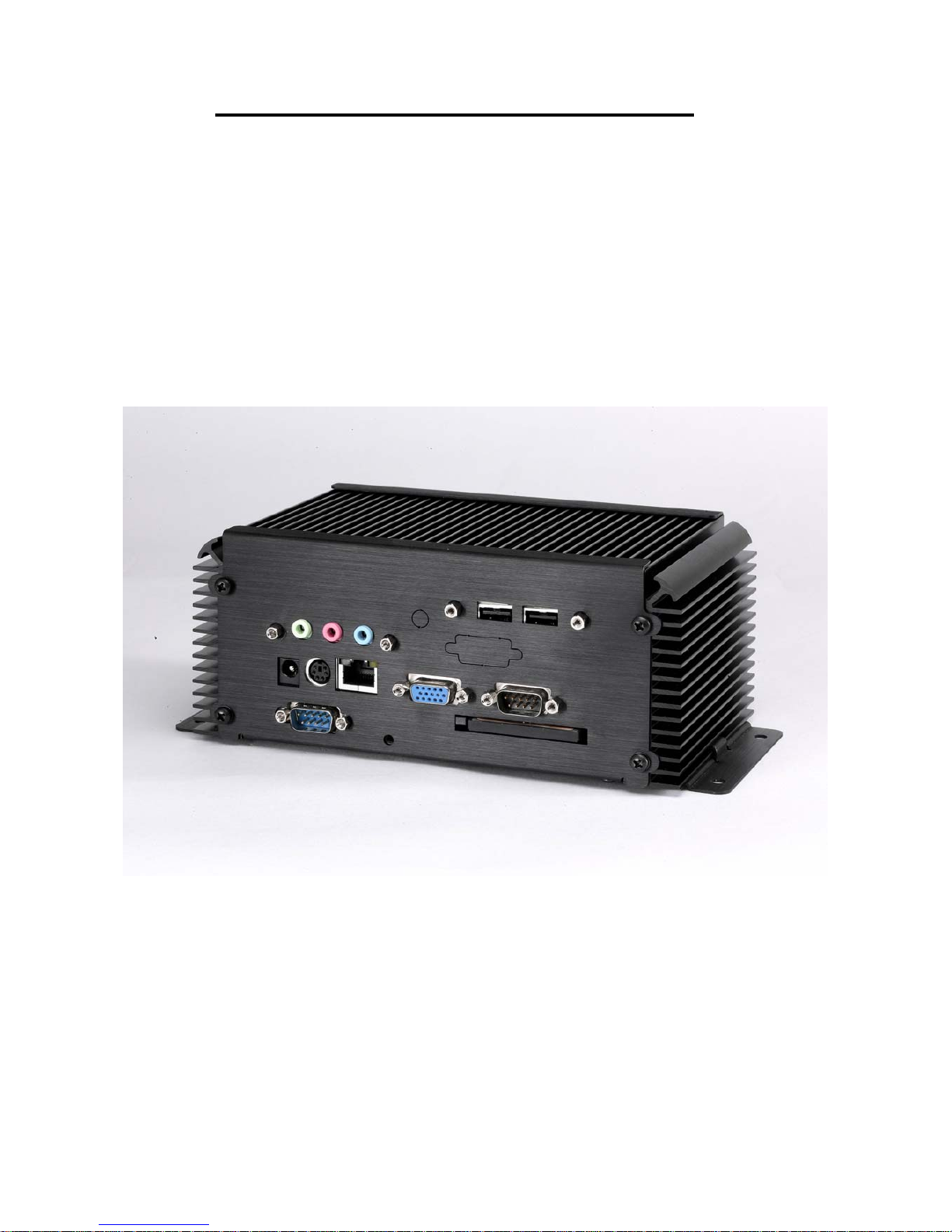
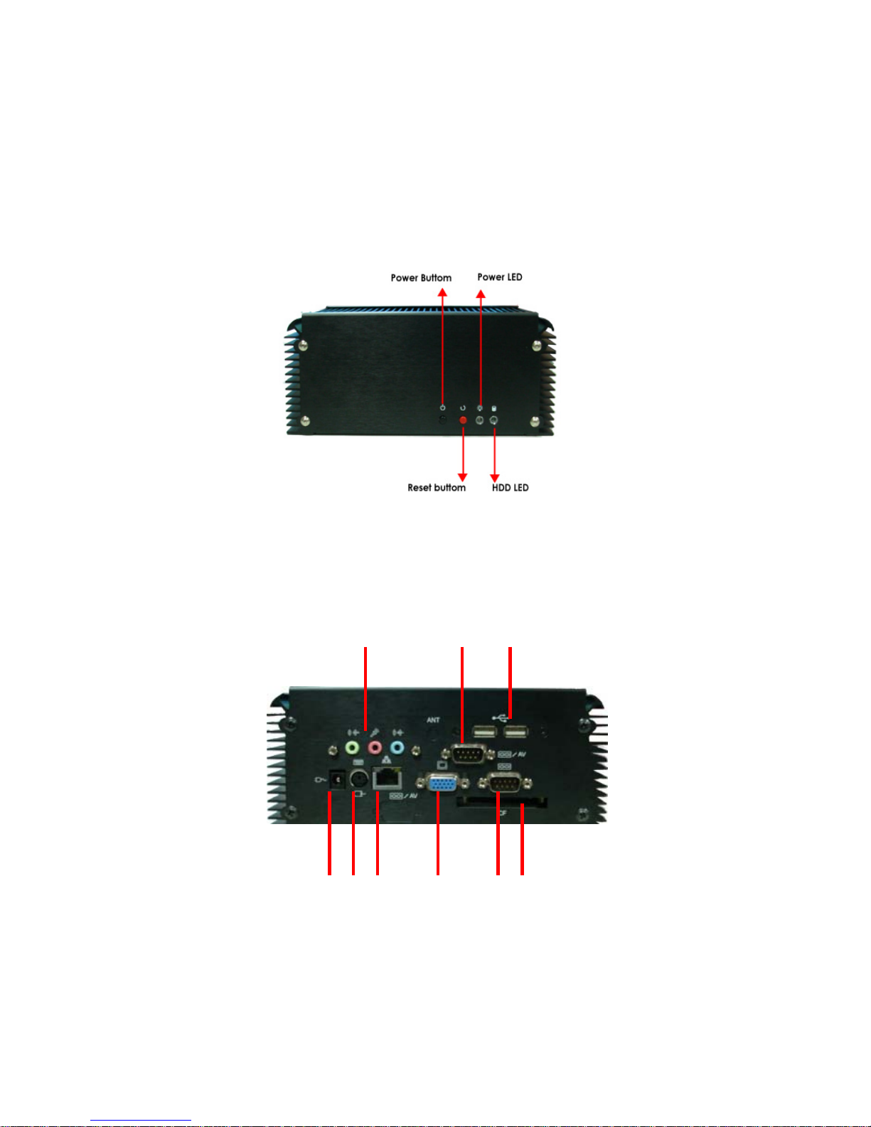
2. Outlook:
Front IO
Rear IO
Audio DB9 to 4 x BNC USB
COM CF socket VGA
LAN
PS/2
KB
(with Y cable support PS/2 KB & MS)
DC IN
Page 6

6
3. Hardware installation Guide:
3-1 Install Heatsink & Copper Pillar 3-2 Insert Memory & Mini-PCI card into MB
3-3 Lock Audio , USB and DB9 cable on the
Rear plate
3-4 Install HDD on the bottom plate
3-5 Connect Audio , USB , DB9 cable with MB 3-6 Screw MB into Copper Pillar
3-7 Lock the Rear plate 3-8 Connect HDD cable and Power / Reset
buttom
3-9 lock the bottom plate 3-10 Assemle Front plate and loak
3-11 Completed
Page 7

7
Note :
The JFRNT provides front control panel of the board, such as power button, reset and beeper, etc. Please check well
before you connecting the cables on the chassis.
Connector: JFRNT
Type: onboard 14-pin (2 x 7) 2.54-pitch header
Function Signal PIN Signal Function
VCC 1 2 VCC
IDE LED
Active 3 4 N/C
Reset 5 6 GND
Power
LED
Reset
GND 7 8 VCC
N/C 9 10 N/C
PWRBT 11 12 N/C
Power
Button
5VSB 13 14 SPKIN
Speaker
1
14
Page 8

8
4. Driver Installation:
4-1
When you completed the Hardware installation, the system will auto –detect And a message pops up as
following:
Please select “ No “.
4-2 Then, Insert the driver CD into your system’s CD-ROM to Set up MP-6802. Run Setup.exe
Please select “ Next “ to continue.
Page 9

9
4-3 Please read the following License Agreement. Press the Page Down key to see the rest of agreement
and click “ Yes “ to continue the installation.
4-4 Please fill in your User Name & Company Name. Then, click “ Next “.
Page 10

10
4-5 Please select a setup type in this page then click “ Next “.
4-6 Click “ Install “ when you see the following message.
Page 11

11
4-7 When the following message appears, click “ Finish “ to complete the installation and restart Windows or
your computer.
4-8 After installation, all the driver is automatically located at the following place:
C:\Program Files\Commate\TCCDCV\Driver and Inf
Page 12

12
5. Sample Program:
5-1 When you completed hardware & software installation, you can use COMMELL “TCCVDCApp” sample
program to test.
You can find TCCDVCApp.exe on desktop.
Please double –click “ TCCDVCApp.exep , It’ll pops up as following.
Then Please Push “ Preview “ on the left-upper Menu.
You ‘ll get the program interface as following.
Page 13

13
Explanation of Sample program function
Device ID:
It is mean Techwell Chipset. One MP-6802
have 1 chipset, so, you only can select 0
Channel ID:
Per chip can support 4 Video input, So, You
can select 0/1/2/3 for Video input.
But you’ll need to set “Channel No Setup”
first.
Channel No Setup:
Please set how many video-In channels per
Device. Per device is allow 4 channels.
Snapshot:
Catch the image on working channel.
Callback T est:
Catch the series image on working channel
Note:
Every channel is work separately, when you
want to change any setting, please stop all
channels which working.
Page 14

14
Device ID & Channel ID sample
Any advice or comment about our products and service, or anything we can help you
please don’t hesitate to contact with us. We will do our best to support you for your products,
projects a business.
Taiwan Commate Computer Inc.
Address
8F, No. 94, Sec. 1, Shin Tai Wu Rd., Shi Chih
Taipei Hsien, Taiwan
TEL +886-2-26963909
FAX +886-2-26963911
Website
TUhttp://www.commell.com.twUT
E-Mail
TUinfo@commell.com.twUT (General Information)
TUtech@commell.com.twUT (Technical Support)
Commell is a trademark of Taiwan Commate Computer Inc.
 Loading...