

Page 1

CMB-B72
Barebone system
Intel High Performance Platform
Installation Guide
Edition 1.01
2017/01/20
Page 2

CMB-B72 User’s Manual
-1-
Copyright
Copyright 2016, all rights reserved. This document is copyrighted and all rights are reserved.
The information in this document is subject to change without prior notice to make
improvements to the products.
This document contains proprietary information and protected by copyright. No part of this
document may be reproduced, copied, or translated in any form or any means without prior
written permission of the manufacturer.
All trademarks and/or registered trademarks contains in this document are property of their
respective owners.
Disclaimer
The company shall not be liable for any incidental or consequential damages resulting from
the performance or use of this product.
The company does not issue a warranty of any kind, express or implied, including without
limitation implied warranties of merchantability or fitness for a particular purpose.
The company has the right to revise the manual or include changes in the specifications of
the product described within it at any time without notice and without obligation to notify any
person of such revision or changes.
Trademark
All trademarks are the property of their respective holders.
Any questions please visit our website at TUhttp://www.commell.com.twUT
Page 3
CMB-B72 User’s Manual
-2-
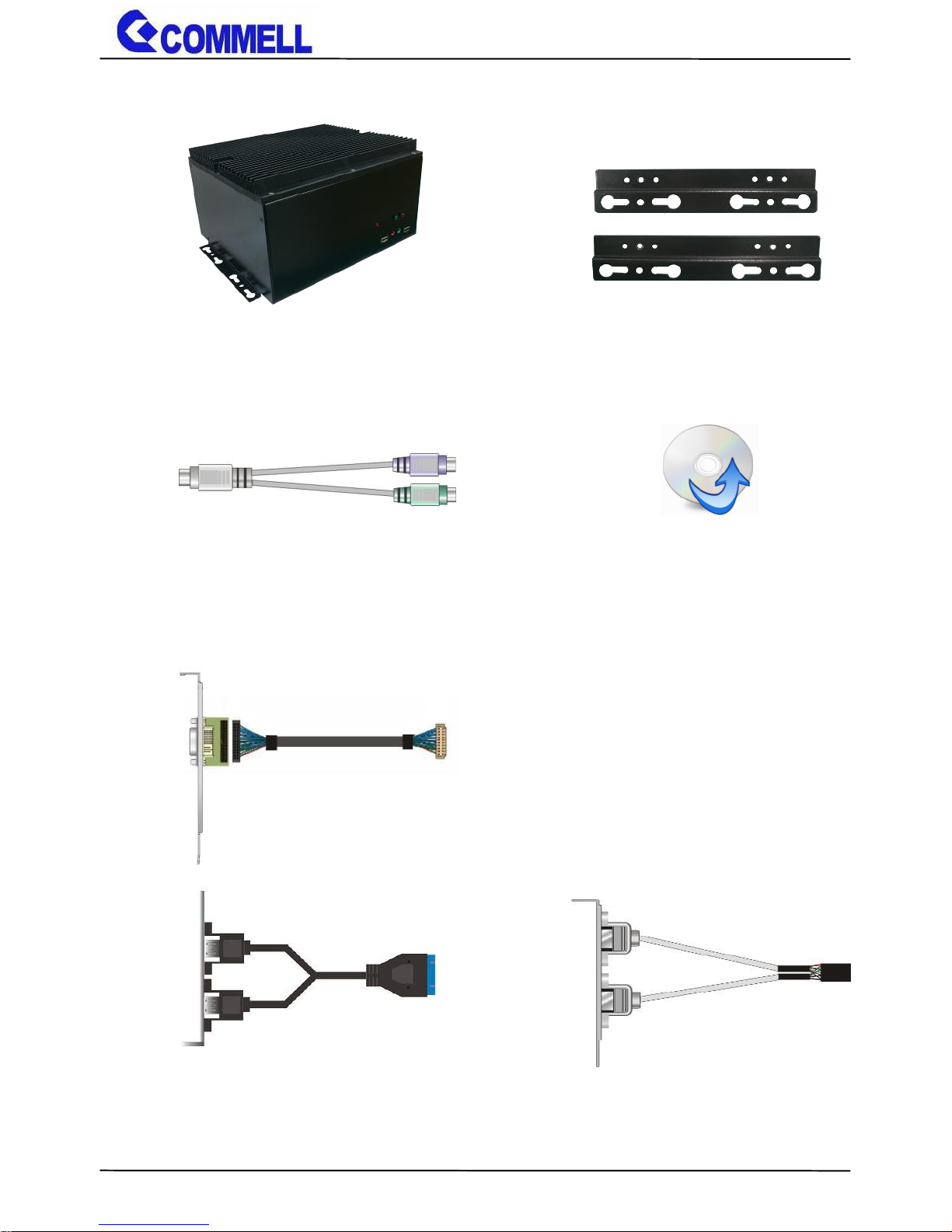
Packing List:
Optional:
CMB-B72 Chassis x 1
(Including Motherboard and Backplane)
CD Driver x 1
Desk/Wall mount x 1 (pair)
1 x PS/2 Keyboard & Mouse Cable
(OALPS2/MKN)/ (1040551)
1 x USB3.0 Cable
(OALUSB3D) / (1040631)
1 x USB2.0 Cable
(OALUSB27S)/ (1040261)
1 x Onboard DVI-D cable (For Secondary DVI)
(BADPDVI_A & OALDVI-DF13-35 )
Page 4

CMB-B72 User’s Manual
-3-
Index
Chapter 1 <Introduction>.................................................................. 4
1.1 <Product Overview> ............................................................ 4
1.2 <Product Specification> ...................................................... 5
Chapter 2 <Product Specification> ................................................... 6
2.1 <Motherboard Placement> .................................................. 6
2.1.1 <Internal connectors list> .......................................... 7
2.1.2 <External connectors list> ......................................... 7
2.2 <Jumper Location and Reference> ..................................... 8
2.2.1 <Jumper list> ............................................................ 8
2.2.2 <Clear CMOS and Power on type selection> ............ 9
2.3 <Motherboard I/O interface> ............................................... 9
2.3.1 <Serial ATA interface> ............................................... 9
2.3.2 <Ethernet interface>................................................ 10
2.3.3 <Display interface> ................................................. 10
2.3.4 <Serial Port interface> ............................................ 12
2.3.5 <USB interface> ...................................................... 14
2.3.7 <Expansion slot>..................................................... 16
2.3.8 <Front panel switch and indicator> ......................... 17
2.4 <Power supply> ................................................................ 18
2.4.1<DC-DC4 Power Convert Module> .......................... 18
2.5 <Expansion slot> ............................................................... 20
2.5.1<PCIMG1.3 Half-size Backplane> ........................... 20
2.6 <I/O Panel> ....................................................................... 23
2.6.1 <Front> ................................................................... 23
2.6.2 <Rear> .................................................................... 24
Chapter 3< Hardware Installation> ................................................. 25
3.1<Chassis Setup Procedure> .............................................. 25
3.1.1<Memory Setup> ..................................................... 25
3.1.2<HDD Setup> ........................................................... 27
3.1.2<Expansion Slot Setup> ........................................... 29
Appendix A <Install Desk/Wall mount> ........................................... 31
Page 5

CMB-B72 User’s Manual
-4-
Chapter 1 <Introduction>
1.1 <Product Overview>
CMB-B72 PICMG 1.3 half-size series fanless barebone system based on Intel® 6th
generation "Skylake-H" Core™ i7/i5/i3 processor with three expansion slots, is designed to
meet the expansion capability(provides three expansion slots with two different
combinations of PCI and PCIe slots: a. two PCI and one PCIe x16; b. one PCI, one PCIe x1
and one PCIe x16.), high performance, high-end media, broad I/O and fanless for a
flexibility and wide variety of transportation, military, industrial, medical and
telecommunication applications and more.
Intel Skylake-H Processor with Intel® QM170 Chipset PCH-H
The 6th Generation Intel® Core™ H-series processor family is new generation and
multi-core processor built on 14 nanometer process.
provide new HD Graphics 530 support triple displays at the same time, maximum supported
is up to 32GB of DDR4, better performance, flexibility and more enhanced security that is
suitable for a variety of intelligent systems the ideal choice.
All in One multimedia solution
CMB-B72 provides high performance onboard graphics, DisplayPort, DVI-D, VGA and
High Definition Audio, to meet the requirement of the multimedia application.
Skylake remove EHCI, all USB ports are xHCI
When you install Windows 7 with USB device(CDROM, Keyboard, Mouse...), Windows7
can not identify your usb device. You can use SATA CD-ROM and PS/2 to install Windows7.
Page 6

CMB-B72 User’s Manual
-5-
1.2 <Product Specification>
System
Processor
Intel® Skylake Core™ i7/ i5/ i3 H-series Processor FCBGA1440
package
Chipset
Intel® QM170
Memory
2 x DDR4 SO-DIMM 2133 MHz up to 32GB,
Support Non-ECC, unbuffered memory only
Watchdog Timer
Generates a system reset with internal timer for
1 min/s ~ 255 min/s
Real Time Clock
Chipset integrated RTC with onboard lithium battery
Expansion
1 x MiniPCIe (support mSATA),1 x Half Size MiniPCIe
2 x 2.5 inch SATA3 HDD/SSD Bays
1 x PCIe X16 slot, 2 x PCI slot
1 x PCIe X16 slot, 1 x PCIe X1 slot, 1 x PCI slot
Graphics
Chipset
Intel® 9th Gen integrated HD Graphics
Display Interface
1 x DP, 1 x DVI-D (optional for 2 x DVI-D), 1 x VGA
LAN
Chip
1 x Intel® I219-LM Gigabit PHY LAN (Support iAMT11.0)
1 x Intel® I210-AT Gigabit LAN
I/O
Front Panel
2 x USB2.0, 1 x Mic-in, 1 x Line-out,
1 x HDD LED, 1 x Power LED, 1 x Power Button
Rear Panel
1 x DisplayPort, 2 x LAN, 1 x PS/2, 1 x DVI ,1 x VGA, 3 x RS232,
1 x RS232/422/485, 2 x USB3.0, 1 x DC input
Mechanical & Environmental
Power Requirement
DC input 9~30V , 120W
Construction
Heat sink (Aluminum)
Chassis (Iron)
Mounting
Desk/Wall mounting
Dimension
230mm x 200mm x 130mm (L x W x H)
Weight
4 Kg
Temperature
Operating within 0°C~40°C (32°F~104°F)
Storage within -20°C~80°C (-4°F~176°F)
Relative Humidity
0%~90% @ 40°C, non-condensing
or
Page 7
CMB-B72 User’s Manual
-6-
Chapter 2 <Product Specification>
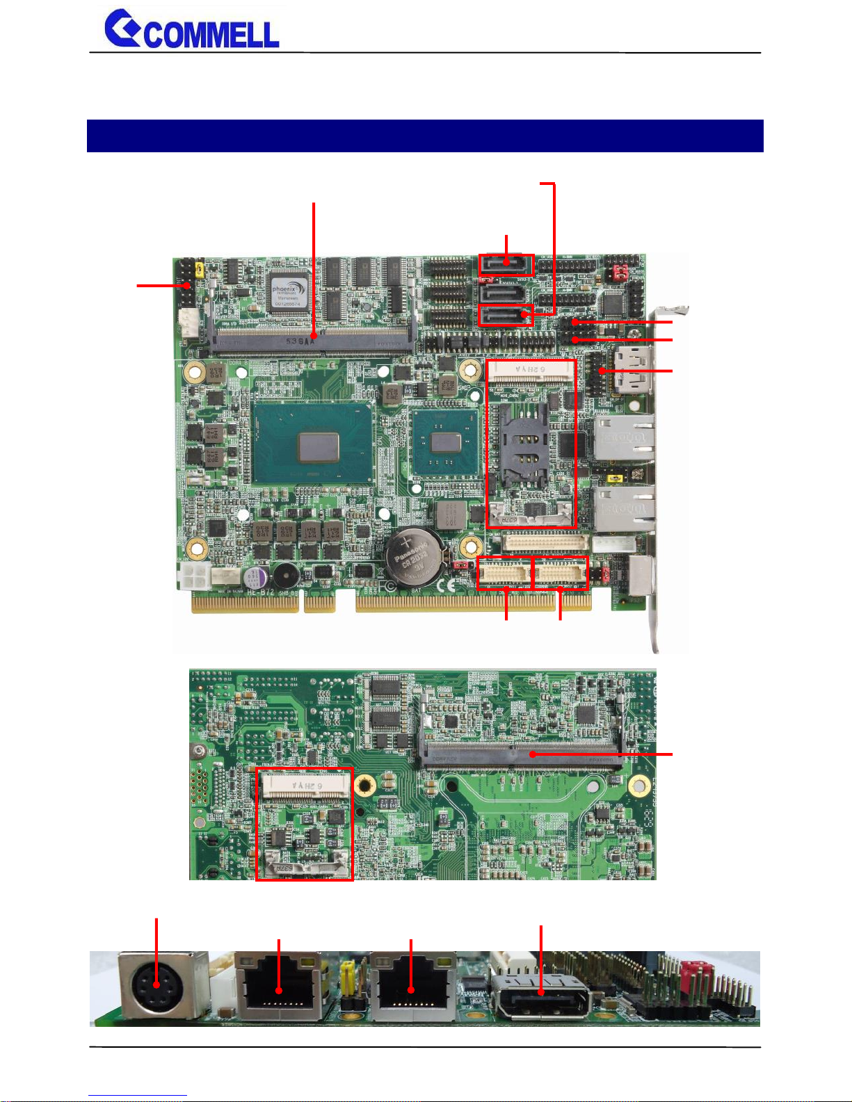
2.1 <Motherboard Placement>
SATA3-3
SATA3-1
JFRNT
I219-LM
I210-AT
PS/2
Display Port
DDR4_B
CN_USB2-2
CN_USB2-1
MINICARD2
DDR4_A
MINICARD1
(RJ45-2)
(RJ45-1)
CN_DVI1
CN_DVI2
CN_CRT
Page 8
CMB-B72 User’s Manual
-7-
2.1.1 <Internal connectors list>
Connector
Function
DDR4_A/B
260-pin DDR4 SO-DIMM slot
SATA3-1/3
7-pin Serial ATA3 connector
CN_USB 2-1 / 2-2
5 x 2-pin USB2.0 pin header
CN_CRT
16-pin VGA connector
CN_DVI1/2
10 x 2-pin DVI connector
JFRNT
14-pin front panel switch/indicator connector
MINI_CARD1
52-pin Half-Size MiniPCIe card slot
MINI_CARD2
52-pin MiniPCIe card slot
2.1.2 <External connectors list>
Connector
Function
DisplayPort
DisplayPort connector
RJ45-1/2
RJ45 connector
PS/2
PS/2 keyboard and mouse connector
Page 9
CMB-B72 User’s Manual
-8-
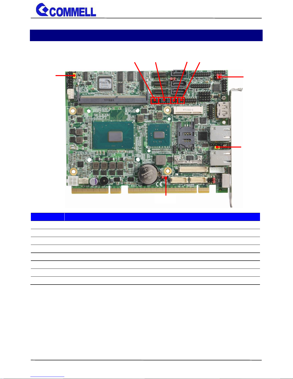
2.2 <Jumper Location and Reference>
2.2.1 <Jumper list>
Jumper
Function
JAT
Power mode select
JRTC
CMOS Normal/Clear Setting
JMSATA
MiniCard 2 mSATA Setting
JP1
COM1 Voltage Setting (For Pin 9)
JP2
COM2 Voltage Setting (For Pin 9)
JCSEL1
COM2 RS-232 RS422 RS485 Setting
JCSEL2
COM2 RS-232 RS422 RS485 Setting
JVUSB
USB Voltage Setting (for USB3.0 VCC setting)
JVUSB
JMSATA
JAT
JCSEL1 JCSEL2 JP1 JP2
JRTC
Page 10
CMB-B72 User’s Manual
-9-
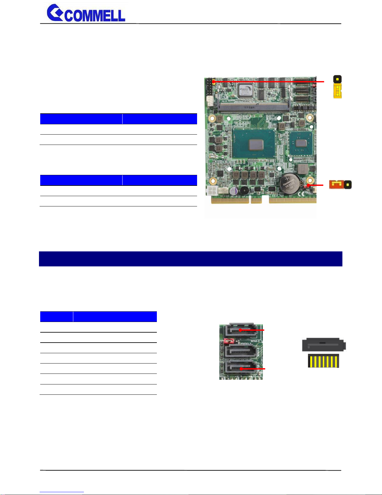
2.2.2 <Clear CMOS and Power on type selection>
The board’s data of CMOS can be setting in BIOS. If the board refuses to boot due to
inappropriate CMOS settings, here is how to process to clear (reset) the CMOS to its default
values.
JAT: AT/ATX mode select jumper
JRTC: Clear CMOS data jumper
Jumper settings
Function
1-2
Clear CMOS
2-3
Normal (Default)
Clear CMOS: Power off, Select jumper from PIN2-3 to PIN1-2, after approx. 10sec, then select the
jumper back to PIN2-3
2.3 <Motherboard I/O interface>
2.3.1 <Serial ATA interface>
SATA 1/3 : SATA3 7-pin connector
Jumper settings
Function
1-2
AT mode
2-3
ATX mode (Default)
Pin
Signal
1
GND
2
TX+
3
TX-
4
GND
5
RX-
6
RX+
7
GND
JRTC
3 1
JAT
1
3
7
1
SATA3-3
SATA3-1
Page 11

CMB-B72 User’s Manual
-10-
2.3.2 <Ethernet interface>
The board provides I219-LM PHY Gigabit Ethernet and I210-AT Gigabit Ethernet
on rear I/O. Intel I219-LM and I210 supports operation at 10/100/1000 Mb/s data
rates, with IEEE802.3 compliance and Wake-On-LAN supported.
2.3.3 <Display interface>
Based on the 6th Gen CPU with built-in HD Graphics 530, VGA and DVI-D up to
1920x1080@60Hz, DisplayPort up to 4096x2304@60Hz.
The built-in HD Graphics support triple display function with clone mode and
extended mode.
I219-LM I210-AT
2
1
20
19
CN_DVI1
2
1
20
19
CN_DVI2
1 2
15 16
CN_CRT
Page 12

CMB-B72 User’s Manual
-11-
CN_CRT: VGA 16-pin connector (Pitch 2.00 mm)
Pin
Signal
Pin
Signal
1
BR 2 BG
3
BB 4 NC
5
IOGND1
6
IOGND1
7
IOGND1
8
IOGND1
9
NC
10
IOGND1
11
NC
12
5VCDA
13
5HSYNC
14
5VSYNC
15
5VCLK
16
NC
CN_DVI: DVIonboard 20-pin connector
Pin
Signal
Pin
Signal
1
+5V 2 N/C
3
HPD 4 Ground
5
TMDSTX0N
6
TMDSTX0P
7
Ground
8
TMDSTX1N
9
TMDSTX1P
10
Ground
11
TMDSTX2N
12
TMDSTX2P
13
Ground
14
Ground
15
TMDSTXCP
16
Ground
17
DVI_DA
18
DVI_SL
19
N/C
20
N/C
Display Port
VGA
DVI-D
(Onboard CN_DVI2)
(Onboard CN_DVI1 for optional DVI cable)
Page 13

CMB-B72 User’s Manual
-12-
2.3.4 <Serial Port interface>
Use JCSEL1 and JCSEL2 to select communication mode
JCSEL1, JCSEL2: For configure COM2 communication mode
Function
JCSEL1
JCSEL2
RS232
(Default)
RS485
RS422
6 1 5 2 12 1 11
2
JCSEL1 JCSEL2 JP1 JP2
6 1 5 2 6 1 5
2
12 1 11
2
5
1
6
2
5 1 6
2
12
1
11
2
12
1
11
2
5
6
2
1
Page 14

CMB-B72 User’s Manual
-13-
JP1, JP2: COM1, COM2 pin-9 setting
Jumper settings
Function
1-2
5V
3-4
12V
5-6
RI (Default)
Effective patterns of connection: 1-2 / 3-4 / 5-6
Other may cause damage
Please inform us above jumper mode before order if necessary to change.
Pin
Signal
Pin
Signal
1
DCD/422TX-/485-
2
RXD/422TX+/485+
3
TXD/422RX+
4
DTR/422RX-
5
GND 6 DSR
7
RTS 8 CTS
9
RI
COM1
COM3
COM2
COM4
1 2 3 4 5
6 7 8 9
Page 15

CMB-B72 User’s Manual
-14-
2.3.5 <USB interface>
CN_USB 2-1/2-2: USB2.0 10-pin header (Pitch 2.54 mm)
Pin
Signal
1
5VSB
2
5VSB
3
DATA0-
4
DATA1-
5
DATA0+
6
DATA1+
7
GND
8
GND
9
GND
10
Key
CN_USB2-1 for optional cable
9 1
10 2
CN_USB2-1
9 1
10 2
CN_USB2-2
CN_USB2-2
Front USB2.0
1 5 2
6
JVUSB
1
10
20
11 1 10
11
20
CN_USB3-1
CN_USB3-2
Page 16

CMB-B72 User’s Manual
-15-
JVUSB: 6-pin Power select jumper (for setting USB3.0 VCC)
Pin
Description
1-3 & 2-4
5V_SB
3-5 & 4-6
5V
Default: 1-3 & 2-4
Effective patterns of connection: 1-3 & 2-4 or 3-5 & 4-6
CN_USB3-1/3-2: USB3.0 20-pin header (Pitch 2.00 mm)
Pin
Signal
Pin
Signal
1
NC
20
VCC (5V_SB/ 5V)
2
VCC (5V_SB/ 5V)
19
USB3.0_RX3-
3
USB3.0_RX4-
18
USB3.0_RX3+
4
USB3.0_RX4+
17
Ground
5
Ground
16
USB3.0_TX3-
6
USB3.0_TX4-
15
USB3.0_TX3+
7
USB3.0_TX4+
14
Ground
8
Ground
13
Data0-
9
Data1-
12
Data0+
10
Data1+
11
NC
CN_USB3-2 for optional cable
CN_USB3-1
CN_USB3-2
Rear USB3.0
Page 17

CMB-B72 User’s Manual
-16-
2.3.7 <Expansion slot>
MINI_CARD2 support mSATA by JMSATA
JMSATA: Setting MINI_CARD2 to support PCIe/mSATA
Jumper settings
Function
1-2
Support mSATA
2-3
Normal operation (Default)
Please inform us the MINI_CARD2 jumper mode before order if necessary.
JMSATA
1
3
MINI_CARD2
MINI_CARD1
Page 18

CMB-B72 User’s Manual
-17-
2.3.8 <Front panel switch and indicator>
JFRNT: Front panel switch and indicator 14-pin header (Pitch 2.54mm)
Pin
Signal
Pin
Signal
1
HDD_LED+
2
Power_LED+
3
HDD_LED-
4
NC
5
NC
6
Power_LED-
7
NC
8
NC
9
Key
10
NC
11
Power_ON+
12
NC
13
Power_ON-
14
NC
JFRNT
1 2
14
13
Power LED
Power Button
HDD LED
Page 19

CMB-B72 User’s Manual
-18-
2.4 <Power supply>
2.4.1<DC-DC4 Power Convert Module>
Power input support 9~30V(120W) wide voltage input.
DC_2H2: Terminal Block 2-pin power connector
Pin
Signal
Pin
Signal
1
GND
3
Power in
1. Power output
13
24
12
1
ATX
4 3 2
1
CN_12V
+ -
3 1
Page 20

CMB-B72 User’s Manual
-19-
CN_12V: 4-pin 12V connector
Pin
Signal
Pin
Signal
1
GND
2
GND
3
12V
4
12V
ATX: main power 24-pin connector
Pin
Signal
Pin
Signal
1
3.3V
13
3.3V
2
3.3V
14
-12V
3
GND
15
GND
4
5V
16
-PSON
5
GND
17
GND
6
5V
18
GND
7
GND
19
GND
8
Power_OK
20
NC
9
5VSB
21
5V
10
12V
22
5V
11
12V
23
5V
12
3.3V
24
GND
For more information refer to the User’s manual
Page 21

CMB-B72 User’s Manual
-20-
2.5 <Expansion slot>
2.5.1<PCIMG1.3 Half-size Backplane>
1. Specification
General Specification
Form Factor
PICMG1.3 Half size Backplane
Extended Interface
1 x PCIe x16 slot,1 x PCIe x1 slot,1 x PCI slot(CBPE-2x1P)
1 x PCIe x16 slot,,2 x PCI slot(CBPE-1x2P)
Power Requirement
Standard 24-pin ATX power supply
Dimension
175.07 x 96.39 mm
SHB Express
ATX
CN_12V
PCIe x16
PCIe x1
PCI
SHB Express
ATX
CN_12V
PCIe x16
PCI
PCI
or
Page 22

CMB-B72 User’s Manual
-21-
2. Power input
Connector: ATX
Connector Type:
Main power 24-pin connector
Pin
Signal
Pin
Signal
1
3.3V
13
3.3V
2
3.3V
14
-12V
3
GND
15
GND
4
5V
16
-PSON
5
GND
17
GND
6
5V
18
GND
7
GND
19
GND
8
Power_OK
20
NC
9
5VSB
21
5V
10
12V
22
5V
11
12V
23
5V
12
3.3V
24
GND
ATX
1
24
13
12
CN_12V
2 3 1
4
13 24
1 12
Page 23

CMB-B72 User’s Manual
-22-
Connector: CN_12V
Connector Type:
12V 4-pin connector
Pin
Signal
Pin
Signal
1
GND
2
GND
3
12V
4
12V
“CN_12V” for increase the input current.
For more information refer to the CBPE-1x2P or CBPE-2x1P User’s manual
1 3
2 4
Page 24

CMB-B72 User’s Manual
-23-
2.6 <I/O Panel>
2.6.1 <Front>
Mic-in
USB2.0
Power LED
Line-out
USB2.0
Power Button
HDD LED
Page 25

CMB-B72 User’s Manual
-24-
2.6.2 <Rear>
DC_IN
I210-AT
DisplayPort
COM1 COM2
COM3 COM4
VGA
USB3.0
DVI-D
PS/2
I219-LM
Expansion slots
For optional cable
Page 26

CMB-B72 User’s Manual
-25-
Chapter 3< Hardware Installation>
3.1<Chassis Setup Procedure>
3.1.1<Memory Setup>
(Two DDR4 SO-DIMM slot up to 32GB)
(a.) Screw off the chassis by the indication as the picture below.
Page 27

CMB-B72 User’s Manual
-26-
(b.) Take off the left side cover and find the DDR4_A/B location.
(c.) Insert the DDR4 SO-DIMM module into the socket at 45 degree.
DDR4_A
DDR4_B
Page 28

CMB-B72 User’s Manual
-27-
(d.) Press down the module with a click sound.
(e.) Put the cover back and screw on the chassis.
3.1.2<HDD Setup>
(a.) Screw off the right side cover.
Page 29

CMB-B72 User’s Manual
-28-
(b.) Put on the HDD into HDD holder then turn the HDD screws to tighten.
2.5" HDD
Page 30

CMB-B72 User’s Manual
-29-
(c.) Plug SATA & SATA power cable into HDD.
(d.) Put the cover back and screw on the chassis.
3.1.2<Expansion Slot Setup>
(a.) Screw off the left side cover.
(b.) Align the keyway of the card with the slot key, and then install the card
securely in the slot.
Page 31

CMB-B72 User’s Manual
-30-
(c.) Lock the bracket.
(d.) Put the cover back and screw on the chassis.
Page 32

CMB-B72 User’s Manual
-31-
Appendix A <Install Desk/Wall mount>
(a.) Screw on the rack mount as the picture below.
Page 33

CMB-B72 User’s Manual
-32-
Contact information
Any advice or comment about our products and service, or anything we can help
you please don’t hesitate to contact with us. We will do our best to support you for
your products, projects and business.
Taiwan Commate computer Inc.
Address
19F., NO.94, Sec. 1, Xintai 5th Rd., Xizhi Dist., New Taipei
City 22102, Taiwan.
TEL
+886-2-26963909
FAX
+886-2-26963911
Website
www.commell.com.tw
E-mail
info@commell.com.tw (General information)
tech@commell.com.tw (Technical Support)
Commell is a brand name of Taiwan Commate computer Inc.
 Loading...