

Page 1

Intrinsically safe barcode scanner
Operating Manual
iSCAN100
Page 2

2
Page 3

Contents
1 Introduction................................................................................................4
2 Safety Information and Notes....................................................................5
3 Installation .................................................................................................6
3.1 PS2 Installation. .........................................................................................6
3.2 RS232 Installation. .....................................................................................7
3.3 Optional Accessory Kits. ............................................................................9
3.3.1 Optional iSCAN100 Extender Junction Box – Part number
iSCAN100JB. ....................................................................................................9
Contains:..........................................................................................................10
4 Operation.................................................................................................11
4.1 How to use the iSCAN100 .......................................................................11
4.2 Audible Indicators ....................................................................................12
4.3 Visual Indicators.......................................................................................13
4.4 Failure Modes ..........................................................................................14
4.5 Programming Modes................................................................................15
4.6 Serial Programming .................................................................................16
4.7 Upgrading The Flash ROM Firmware . ....................................................19
5 Depth of Field and IR Activation ..............................................................20
6 Troubleshooting Guide ............................................................................22
7 Intended Purpose Usage.........................................................................26
8 Technical Data.........................................................................................28
9 Certification .............................................................................................30
10 Booklet Revision Notes ...........................................................................32
3
Page 4

1 Introduction
The iSCAN100 is the latest development in barcode scanning technology for
Zone 1 and Zone 2 hazardous areas. The unit offers a very high specification
but at an affordable price as it is based on the very latest ideas in Ex
protection technology.
The scanner is ergonomically designed in an IP55 pistol grip housing that is
comfortable to use for an operator, even when wearing gloves. The housing has
a rubber protective shield to protect it from dropping on to hard floors.
Supplied with a spiral cable the iSCAN100 can be connected to systems by a
PS2 keyboard wedge or an RS232 serial interface. Most popular barcode
symbologies are supported by the built-in decoder providing the PC or operator
terminal with ASCII data.
A friction free scanning mechanism is designed to be highly reliable and give a
long service life. Scanning 72 times per second at up to 33 cm away from the
barcode makes this unit very practical to use for demanding applications
Each type is rigorously checked and tested by Extronics to ensure conformity
to the ATEX standards and approvals.
.
4
Page 5
2 Safety Information and Notes
Keep this user manual safe and in the vicinity of the device. All persons who have to work
on or with the device should be advised on where the manual is stored.
Warning Installation to be by skilled electricians and instructed personnel in
accordance with national legislation, including the relevant standards
and, where applicable, in accordance with IEC 79.17 on Electrical
Apparatus for Explosive Atmospheres.
Warning! The iSCAN100 can be used in gas zones 2 & 1 BUT NOT 0!
Warning! The iSCAN100 must only be connected and powered from a suitably
approved intrinsically safe interface .
Important The technical data indicated on the iSCAN100 must be observed.
Important Changes in the design and modifications to the equipment are not
permitted.
Important The iSCAN100 shall be operated as intended and only in undamaged
and perfect condition.
. DANGER! RADIATION FROM LIGHT EMITTING DIODES DO NOT LOOK
INTO THE BEAM, DO NOT POINT THE BEAM AT PERSONS OR
AN I M ALS
Light power <1mW
Class 1 Laser product
5
Page 6

Mouse
Keyboard
Keyboard
Mouse
Mouse
Keyboard
RS232
RS485
Mouse
Keyboard
Keyboard
Mouse
Mouse
RS232
RS485
3 Installation
3.1 PS2 Installation
For the PS2 version while power is off plug the male PS2 connector on the
iSCAN100 cable into the female socket on the Extronics iSOLATE100 or similar
intrinsically safe interface.
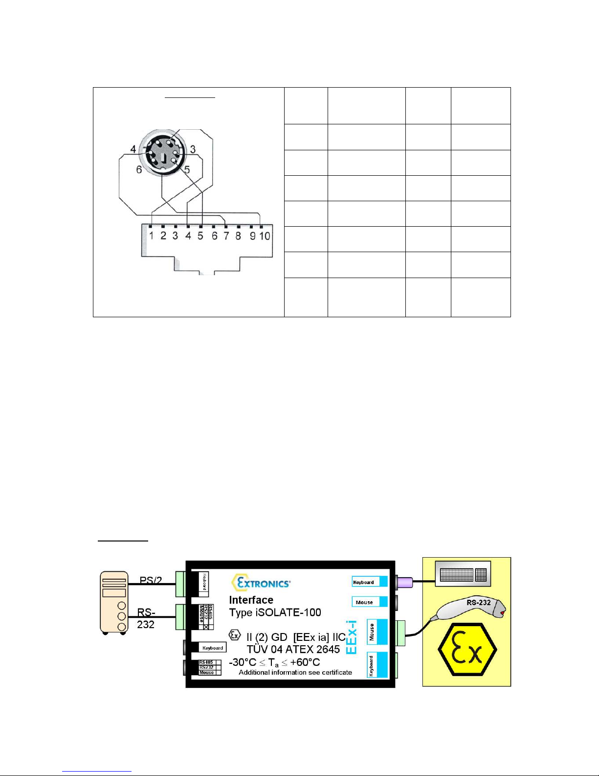
Examples and Connection details for the PS/2 can be found in Diagram 3.1 below
Examples iSCAN100 PS/2 scanner connections using the iSOLATE100 Ex01:
Example 1 Without Keyboard.
Diagram 3.1
The iSCAN100 PS/2 scanner can be connected on the hazardous side instead of
the keyboard. In this configuration the mouse may or may not be connected.
Keyboard
Interface
RS232
Mouse
RS485
Type iSOLATE100
II (2) GD [EEx ia] IIC
TÜV 04 ATEX 2645
-30°C ≤ Ta ≤ +60°C
Additional information see certificate
PS/2
EEx-i
Since a scanner does not answer to the PC's request the PC might switch off the
keyboard line after booting. In this case please cancel the keyboard test in the
BIOS settings of your PC or wire a keyboard in parallel to the scanner.
Example 2 With Keyboard.
Diagram 3.2
Keyboard
RS232
RS485
Interface
Mouse
Type iSOLATE100
II (2) GD [EEx ia] IIC
TÜV 04 ATEX 2645
-30°C ≤ Ta ≤ +60°C
Additional information see certificate
Keyboard
EEx-i
Furthermore you may connect a keyboard with the safe side of iSOLATE100 using
its built-in keyboard wedge. Please refer to version Ex02.
PS/2
6
Page 7
iSCAN100 PS2 Connection Details
Diagram 3.2
PS2
Nodes
Description Colour RJ45
Nodes
PS2 Plug (male) of scanner cable
1 Data
2 Not
Yellow 2
N/A N/A
Connected
3 Ground White 3
4 Supply Brown 4
5 Clock Green 1
6 Not
N/A N/A
connected
10-Pole RJ45 socket of the scanner
Shield Not
connected
N/A N/A
Note: If your iSCAN100 has a PS2 plug fitted when purchased cable colours may
vary from those indicated in this diagram
3.2 RS232 Installation
For the RS232 version while power is off wire the cable to the terminals on the
iSOLATE100 or similar intrinsically safe interface.
Examples and Connection details for the PS/2 can be found in Diagram 4.2 below
Version Ex03
Diagram 3.4
7
Page 8

The iSOLATE100 Ex03 mode allows one keyboard and or one RS-232 scanner
device in the EEx i area. The scanner must be connected to one of the mouse
terminals at the hazardous side, this is still the case even if there is no keyboard.
PS/2 and screw terminals for the hazardous area are wired in parallel.
iSCAN100 RS232 Cable Connection Details
Description Core Colour
TxD Green
Rxd Yellow
GND White
+5V Supply Brown
8
Page 9
3.3 Optional Accessory Kits
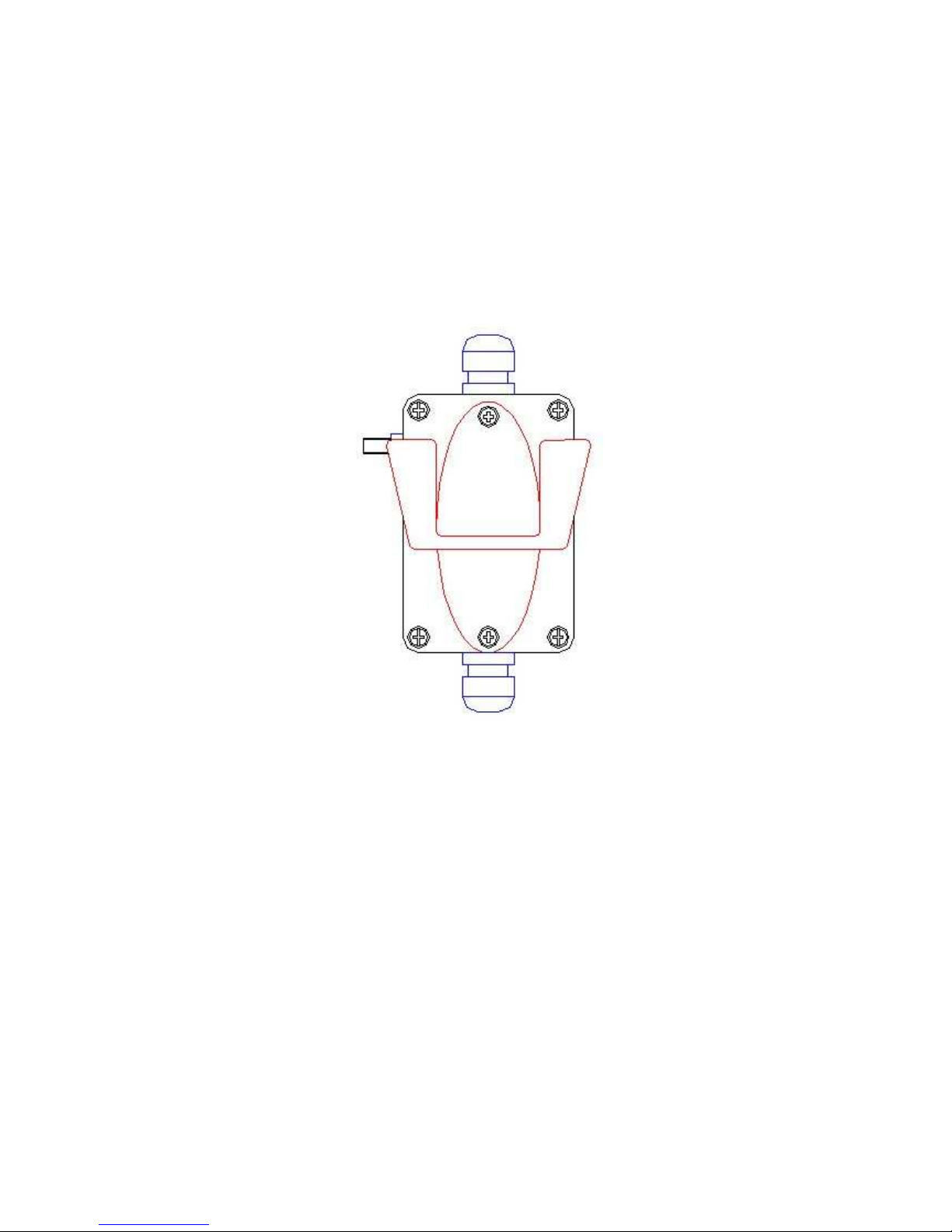
3.3.1 Optional iSCAN100 Extender Junction Box – Part number iSCAN100JB
The iSCAN100 Extender Junction Box combines a junction box and wall mounting
stand, allowing the ISCAN100 to be connected to the junction box in a hazardous
area, and up to 50 metres of cable
9
Page 10
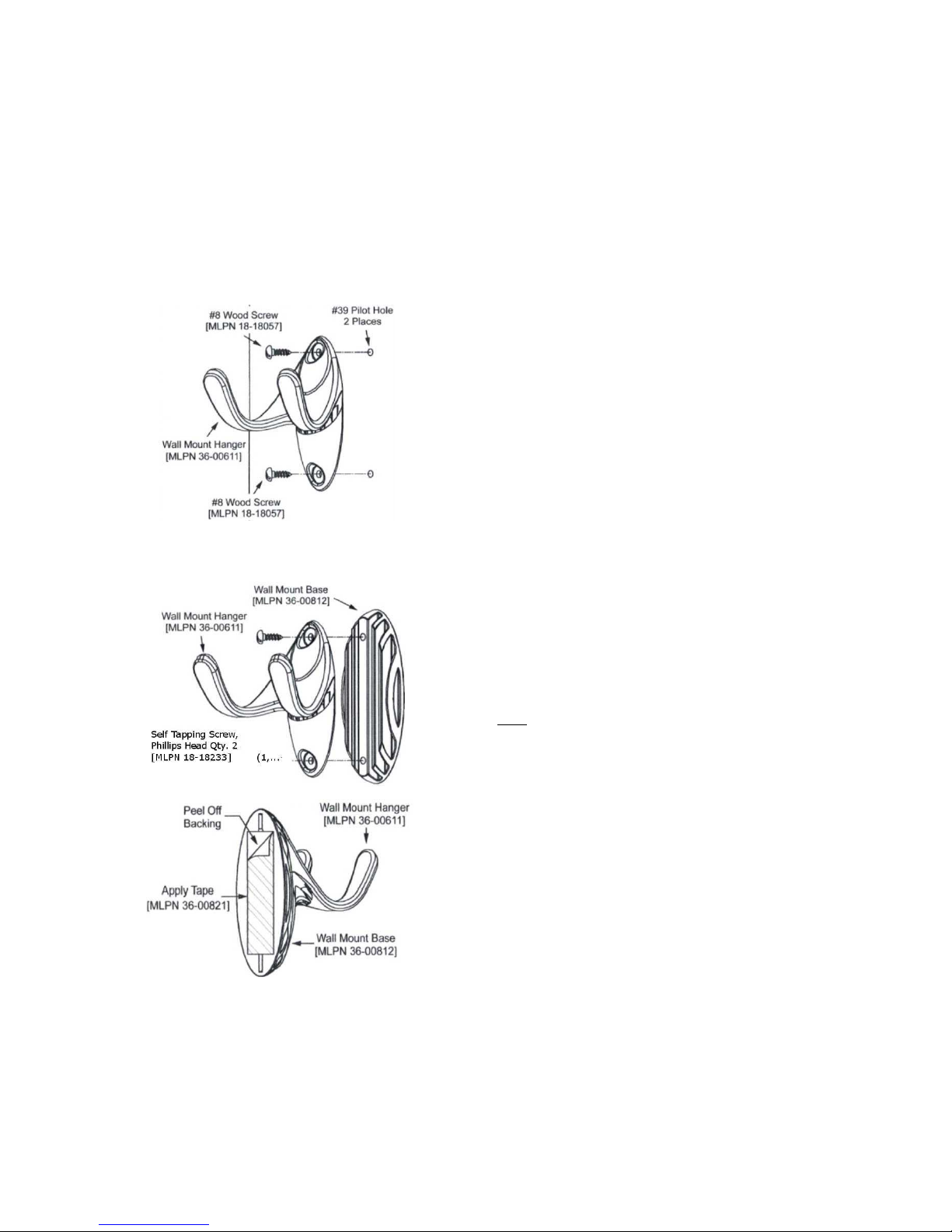
Optional Wall Mount Hanger Kit #46-46508
Contains:
a) Wall mount hanger (MLPN 36-00611) Qty 1
b) Wall mount base (MLPN 36-00812 Qty 1
c) Self tapping screw (MLPN 18-18233 Qty 2
d) Double sided tape Qty 1
e) #8 wood screw Qty 2
Wall Mount, Option 1:
Step 1:
Drill two #39 pilot holes 3.00" apart.
Step 2:
Attach the Wall Mount Hanger to the wall with the
two #8 wood screws provided.
Wall Mount, Option 2:
Step 1
Attach the Wall Mount Base to the Wall Mount
Hanger with the two 4.8 x 13 mm self-tapping
screws.
Step 2
Remove one side of the protective backing
from the double-sided adhesive tape
Step 3
Attach the tape to the back of the wall mount base.
Step 4
Remove the remaining backing from the tape and attach
to the wall.
10
Page 11

4 Operation
4.1 How to use the iSCAN100
Aim the Scanner at the barcode and follow the instructions below
• Auto trigger
activates the
laser
• Place the
laser line on
the bar code
• Press the
CodeGate
button to
transmit the
data
11
Page 12

4.2 Audible Indicators
When the iSCAN100 is in operation, it provides audible feedback. These sounds
indicate the status of the scanner. Eight settings are available for the tone of the
beep (normal, 6 alternate tones and no tone). To change the tone, refer to the
MetroSelect® Single-Line Programming Guide
Alternativleysee the help files contained in the
One Beep
When the scanner first receives power, the green LED will turn on, then the red
LED will flash and the scanner will beep once. (The red LED will remain on for
the duration of the beep.) The scanner is ready to scan.
When the scanner successfully reads a bar code, the red LED will flash and the
scanner beeps once (if programmed to do so). If the scanner does not beep once
and the green light does not flash, then the bar code has not been successfully
read.
included with the scanner.
MetroSet®2 help files.
Two Beeps — On Power Up
When there is a Flash ROM upgrade needed, the scanner will beep twice
followed by alternating flashing of the green and red LEDs.
Three Beeps - During Operation
When entering configuration mode, the red LED will flash while the scanner
simultaneously beeps three times. The red and green LEDs will continue to flash
while in this mode. Upon exiting configuration mode, the scanner will beep three
times, and the LEDs will stop flashing.
When configured, 3 beeps can also indicate a communications time-out
during normal scanning mode.
When using one-code-programming, the scanner will beep three times (the
current selected tone), followed by a short pause then by a high tone and a low
tone. This tells the user that the single configuration bar code has successfully
configured the scanner.
Raspberry Tone\Three Beeps - On Power Up
This is a failure indicator. Refer to "Failure Modes" on page 14.
12
Page 13
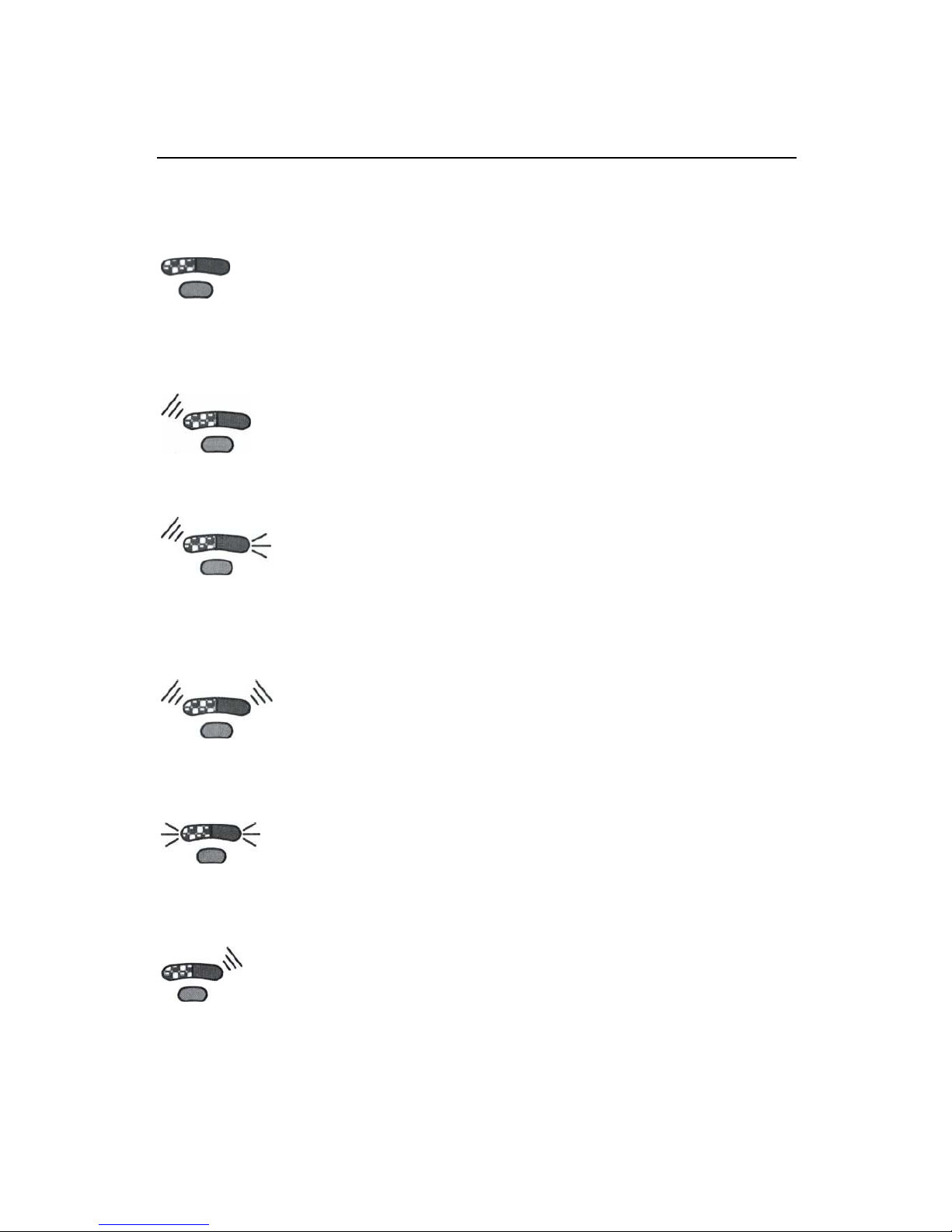
4.3 Visual Indicators
The iSCAN100 has three LED indicators (green, red and yellow) located on the
head of the scanner. The MS9520 has two LED indicators (green and red) located
on the head of the scanner. When the scanner is on, the flashing or stationary
activity of the LEDs indicates the status of the current scan and the scanner.
Green & red LED’s off
The LEDs will not be illuminated if the scanner is not receiving power from
the host or transformer. The scanner is stand-by mode, and CodeGate® is
enabled. Present a bar code to the scanner and the green LED will turn on
when the laser turns on.
Steady Green
When the laser is active, the green LED is illuminated. The green LED will
remain illuminated until the laser is deactivated. (Default Mode Only)
Steady Green and Single Red Flash
When the scanner successfully reads a bar code, the red LED will flash and the
scanner will beep once. If the red LED does not flash or the scanner does not
beep once, then the bar code has not been successfully read.
(Default Mode Only)
Steady Green and Steady Red
After a successful scan, the scanner transmits the data to the host device. Some
communication modes require that the host inform the scanner when data is ready
to be received. If the host is not ready to accept the information, the scanner's red
LED will remain on until the data can be transmitted.
Alternating Flashing of Green and Red
This indicates the scanner is program mode. A raspberry tone indicates that an
invalid bar code has been scanned while in this mode.
The scanner needs to have a Flash ROM upgrade if the alternating flashing of the
red and green LEDs occurs during start-up and is accompanied by three beeps.
Steady Red, Green off
This indicates the scanner may be waiting for communication from the host.
13
Page 14

4.4 Failure Modes
Flashing Green and one Raspberry Tone
This indicates the scanner has experienced a laser sub-system failure. Return
the unit for repair to an authorized service centre.
Flashing Red and Green with Two Raspberry Tones
This indicates the scanner has experienced a scanning mechanism failure.
Return the unit for repair to an authorized service centre.
Continuous Raspberry Tone with all LEDs off
If, upon power up, the scanner emits a continuous raspberry tone, then the
scanner has an experienced an electronic failure. Return the unit for repair to
an authorized service centre.
Three Beeps – on power up
If the scanner beeps 3 times on power up then the non-volatile memory
(NovRAM) that holds the scanner configuration has failed. If the scanner does
not respond after reprogramming, return the scanner for repair to an
authorized service center.
14
Page 15

4.5 Programming Modes
The ISCAN100 has 3 modes of configuration.
• Bar Codes
iSCAN100 can be configured by scanning the bar codes located in the
MetroSelect® Single-Line Programming Guide supplied with the
scanner. Please refer to this guide for instructions.
• MetroSet®2
This user-friendly Windows-based configuration program allows you to simply
`point-and-click' at the desired scanner options. This program can be
downloaded for FREE from the following URL:
www.europe.metrologic.com/europe/download/software/metroset2install.exe.
• Serial Programming
This mode of programming is ideal for OEM applications. This mode gives
the end-user the ability to send a series of commands using the serial port of
the host system. The commands are equivalent to the numerical values of
the bar codes located in the MetroSelect Single-Line Programming Guide
supplied with the scanner.
15
Page 16

4.6 Serial Programming
Each command sent to the scanner is the ASCII representation of each numeral in
the configuration bar code. The entire numeric string is framed with an ASCII [stx]
and an ASCII [etx].
EXAMPLE #1:
Command for Disabling Codabar Command = [stx]100104[etx]
String Sent to Scanner = 02h 31h 30h 30h 31h 30h 34h 03h
(All values are hexadecimal).
If the command sent to the scanner is valid, the scanner will respond with an [ack].
If the command sent to the scanner in invalid, the scanner will respond with a
[nak].
NOTE: If this occurs, the end-user must start over at the very beginning of the
configuration sequence. Simply re-transmitting the invalid command will not work,
you must start over.
During programming, the motor and laser turn off. YOU CANNOT SCAN A BAR
CODE WHILE IN SERIAL PROGRAM MODE.
There is a 20 second window between commands. If a 20 second time-out occurs,
the scanner will send a [flak] and you must start over.
To enter serial program mode, send the following command [stx]999999[etx].
To exit serial program mode, send the following command [stx]999999[etx], the
scanner will respond with an [ack] followed by 3 beeps.
This mode uses the current Baud Rate, Parity, Stop Bits and Data Bits settings
that are configured in the scanner. The default settings of the scanner are 9600,
Space, 2, 7 respectively. If a command is sent to the scanner to change any of
these settings, the change will NOT take effect until after serial program mode is
exited.
16
Page 17

EXAMPLE #2:
The following example will set the scanner to the factory default settings, Disable
Scanning of Code 128 bar codes, change the beeper tone, and add a "G" as a
programmable prefix.
FEATURE HOST
COMMAND
Enter Program Mode [stx]999999[etx]
ASCII REPRESENTATION SCANNER
RESPONSE
02h 39h 39h 39h 39h 39h 39h 03h [ack] or 06h
Load Defaults [stx]999998[etx]
Disable Code 128 [stx]100113[etx] 02h 31h 30h 30h 31h 31h 33h
Alternate Tone 1 [stx]318565[etx]
Prog. Prefix #1 [stx]903500[etx]
Code Byte 0 [stx]0[etx] 02h 30h 03h [ack] or 06h
Code Byte 7 [stx]7[etx] 02h 37h 03h [ack] or 06h
Code Byte 1 [stx]1[etx] 02h 31h 03h [ack] or 06h
Exit Program Mode [stx]999999[etx]
The scanner will beep three times!
02h 39h 39h 39h 39h 39h 38h 03h [ack] or 06h
[ack] or 06h
02h 33h 31h 38h 35h 36h 35h 03h [ack] or 06h
02h 39h 30h 33h 35h 30h 30h 03h [ack] or 06h
02h 39h 39h 39h 39h 39h 39h 03h [ack] or 06h
The commands sent to the scanner do not include the small superscripted `3' that
you see in front of each bar code string in the MetroSelect manual. THE '3'
SHOULD NOT BE SENT, IT IS A CODE TYPE DESIGNATION ONLY!
As you will note for commands requiring additional bar codes to be scanned (such
as prefixes, suffixes, time-outs, etc.), simply send the code bytes in the same order
that you would normally scan the bar codes.
17
Page 18

HOST
EXAMPLE #3:
The following example shows the events that occur when an invalid bar code is sent.
This sample will load the factory default settings and then set the baud rate to
19200.
FEATURE COMMAND ASCII REPRESENTATION RESPONSE
Enter Program Mode [stx]999999[etx] 02h 39h 39h 39h 39h 39h 39h 03h [ack] or 06h
Load Defaults [stx]99999:[etx] 02h 39h 39h 39h 39h 39h 3Ah 03h [nak] or 15h
Invalid command was sent, you must start over!
Enter Program Mode [stx]999999[etx] 02h 39h 39h 39h 39h 39h 39h 03h
Load Defaults [stx]999998[etx] 02h 39h 39h 39h 39h 39h 39h 03h [ack] or 06h
19200 Baud Rate [stx]415870[etx] 02h 34h 31h 35h 38h 37h 30h 03h [ack] or 06h
Exit Program Mode [stx]999999[etx] 02h 39h 39h 39h 39h 39h 39h 03h [ack] or 06h
The scanner will beep three times!
SCANNER
[ack] or 06h
This example illustrates two important points.
First, if an invalid command is sent from the host, the scanner responds with a [nak]
and the end-user must start over from the beginning.
Second, if a command is sent to change the Baud Rate, the new baud rate does
not take effect until after the end-user exits program mode.
ABBREVIATED ASCII TABLE
Character Hex Value Decimal Value
[SIX] 02h 2
[ETX] 03h 3
[ACK] 06h 6
[NAK] 15h 21
0 30h 48
1 31 h 49
2 32h 50
3 33h 51
4
5
6 36h 54
7 37h 55
8 38h 56
9 39h 57
34h 52
35h 53
18
Page 19

4.7 Upgrading The Flash ROM Firmware
The Meteor program is a functional component of Extronics new line of Flashbased scanners. This program allows the user of Extronics scanner to quickly
upgrade to a new or custom version of software. It requires the use of a personal
computer running under Windows 95 or greater and the use of a communication
port. The user merely connects the scanner to a communications port of the PC,
launches the Meteor program, and blasts off to new software upgrades.
Each MS9500, regardless of the version number or communication protocol, can
be upgraded. In other words, all RS232 (-41), keyboard wedge (-47), light pen (-
41), laser emulation (-00), OCIA (-9) and IBM 468X/469X (-11) units can be
upgraded. To upgrade all units, a power supply and PowerLink cable
54012) are required.
The upgrades and custom software versions will be supplied by Extronics in files
called Motorola S-record files. These files contain all the information needed to
upgrade the scanner. Simply add this file to the working directory or retrieve from
its current location.
The program guides the user with its simplistic one click approach. The user must
first select the file; once selected and verified, the file is ready to be used in the
upgrade. Press the button to upgrade the scanner, the unit will go into a "flash
mode" — both the green and red LEDs will be on. The user can follow the progress
of the upgrade by watching the screen for details. When the upgrade is complete,
the scanner will respond with its normal one beep on power up. If two beeps occur,
the scanner did not upgrade properly. (Contact an Extronics for additional details).
(MLPN
54-
19
Page 20

5 Depth of Field and IR Activation
Minimum Bar Code Element Width
Code Element
Width A B C D E F G H J
mm 0.13 0.15 0.19 0.25 0.33 0.53 -
mils
5.2 5.7 7.5 10 13 21
20
K
Page 21

21
Page 22

6 Troubleshooting Guide
A power supply may be needed.
VLD failure
Adjust same symbol time
All Interfaces
iSCAN100 Series Troubleshooting Guide
Symptoms Possible Causes Solution
No LEDs, beep
or laser
No LEDs, beep,
or laser
2 Beeps with
alternately
flashing LEDs
on Power up
3 Beeps on
power up
Continuous razz
tone on power
up
Razz tone and
green LED flash
at power up
No power is being
supplied to the
Scanner
No power is being
supplied to the
Check transformer, outlet and
power strip. Make sure the cable
is plugged into the scanner.
Some host systems cannot supply
enough current to power Voyager.
scanner from host
Possible ROM failure Flash ROM Upgrade Required
Non-volatile RAM
failure
Contact an Extronics
Representative, if the unit will not
hold the programmed
configuration.
RAM or ROM failure Contact an Extronics
Representative, if the unit will not
function.
Contact an Extronics
Representative
Razz tone, red
and green LEDs
flash at power
up
Unit scans,
Communicates
and beeps twice
The unit powers
up, but does not
scan/or beep
Scanning mechanism
failure
Same symbol time-out
set too short
Beeper disabled. No
tone selected
Contact an Extronics
Representative
-out for a
longer time.
Enable beeper. Select tone.
Page 23

Verify that the type of bar code
Verify that the bar code that is
locks
ACK/NAK, RTS/CTS, XON/XOFF
but
Verify that the scanner's data
Symptoms Possible Causes Solution
The unit powers
up, but does not
scan and/or
beep
The unit powers
up, but does not
scan and/or
beep
The unit scans a
bar code, but
up after the first
scan red LED
stays on
The unit scans,
the data
transmitted to
the host is
incorrect
Scanning a particular
symbology that is not
enabled
The scanner has
been programmed for
a character length
lock, or a minimum
length and bar code
being scanned does
not satisfy the
programmed criteria
The scanner is
configured to support
some form of host
handshaking but is not
receiving the signal
The scanner's data
format does not
match the host
system requirements
UPC/EAN, Code 39, interleaved 2
of 5, Code 93, Code 128 and
Codabar are enabled by default.
being read has been selected.
being scanned falls into the
criteria Typical of Non-UPC/EAN
codes) The scanner defaults to a
minimum of 3 character bar code.
If the scanner is setup to support
or
D/E, verify that the host cable and
host are supporting the handshaking
properly.
format matches that required by
the host. Most sure that the
scanner is connected to the
proper host port.
Scanner beeps
at some bar
codes and NOT
for others of the
same bar code
symbology
Scanner beeps
at some bar
codes and NOT
for others of the
same bar code
symbology
The print quality of
the bar code is
suspect
The aspect ratio of
the bar code is out of
tolerance
Check print mode. The type of
printer could be the problem.
Change print settings. i.e. change
to econo mode or high speed.
Check print mode. The type of
printer could be the problem.
Change print settings. i.e. change
to econo mode or high speed.
23
Page 24

AT, PS2 or XT is selected. Verify
Symptoms Possible Causes Solution
Scanner beeps
at some bar
codes and NOT
for others of the
same bar code
symbology
Scanner beeps
at some bar
codes and NOT
for others of the
same bar code
symbology
Scanner beeps
at some bar
codes and NOT
for others of the
same bar code
symbology
The unit scans
the bar code but
there is no data
The bar code may
have been printed
incorrectly
The scanner is not
configured correctly
for this type of bar
code
The minimum symbol
length setting does
not work with the bar
code
Configuration is not
correct
Check if it is a check
digit/character/or border problem.
Check if check digits are set
properly.
Check if the correct minimum
symbol length is set.
Make sure the scanner is
configured for the appropriate
mode.
The unit scans
but the data is
not correct
The unit is
transmitting
each character
twice
Configuration is
correct
Configuration is not
correct
Make sure that the proper PC type
correct country code and data
formatting are selected. Adjust
inter-character delay symptom.
Increase interscan code delay
setting. Adjust whether the FO
break is transmitted. It may be
necessary to try this in both
settings.
24
Page 25

Alpha
works except for
Add some inter
Symptoms Possible Causes Solution
characters show
as lower case
Everything
a couple of
characters
Power-up OK
and scans OK but
does not
communicate
properly to the
host
Power-up OK
and scans OK
but does not
communicate
properly to the
host
Computer is in Caps
Lock mode
These characters
may not be supported
by that country's key
look up table
Corn port at the host
is not working or
configured properly
Cable not connected
to the proper corn
port
Enable Caps Lock detect setting
of the scanner to detect whether
the PC is operating in Caps Lock.
Try operating the scanner in Alt
mode.
Check to make sure that the baud
rate and parity of the scanner and
the communication port match
and the program is looking for
"RS-232" data.
Check to make sure that the baud
rate and parity of the scanner and
the communication port match
and the program is looking for
"RS-232" data.
Power-up OK
and scans OK
but does not
communicate
properly to the
host
The host is
receiving data
but the data
does not look
correct
Characters are
being dropped
Cable not connected
to the proper corn
port
The scanner and host
may not be
configured for the
same interface
parameters
Inter-character delay
needs to be added to
the transmitted output
Check to make sure that the baud
rate and parity of the scanner and
the communication port match
and the program is looking for
"RS-232" data.
Check that the scanner and the
host are configured for the same
interface parameters
-character delay to
the transmitted output by using
the MetroSelect Single-Line
Programming Guide MLPN
00-02544.
25
Page 26

7 Intended Purpose Usage
Important Before setting the units to work, read the technical documentation
carefully.
Important The latest version of the technical documentation or the corresponding
technical supplements is valid in each case.
The iSCAN100 is built using modern components and is extremely reliable in
operation; however it must only be used for its intended purpose. Please note that
the intended purpose also includes compliance with the instructions issued by the
manufacturer for installation, setting up and service.
Any other use is regarded as conflicting with the intended purpose. The manufacturer
is not liable for any subsequent damage resulting from such inadmissible use. The
user bears the sole risk in such cases.
Transportation and Storage
All iSCAN100 devices must be so transported and stored that they are not subjected
to any excessive mechanical stresses.
Authorized Persons
Only persons trained for the purpose are authorized to handle the iSCAN100; they
must be familiar with the unit and must be aware of the regulation and provisions
required for explosion protection as well as the relevant accident prevention
regulations.
Cleaning and Maintenance
The iSCAN100 and all its components require periodic inspection. All work on the
iSCAN100 by personnel who are not expressly qualified for such activities will cause
the Ex approval and the guarantee to become void.
The scanner may be cleaned with a damp cloth or a brush. The laser window may
be cleaned from periodically with a very soft cloth. The scanner must not be
cleaned within the Ex area due to potential charging of the cleaning tool
The protective conducting layer must not be damaged. If there is visible damage of
significant areas of the layer the scanner must not be used inside of Ex areas until it has
been repaired by the manufacturer
26
Page 27

Safety Precautions
Important For the installation, maintenance and cleaning of the units, it is
absolutely necessary to observe the applicable regulations and provisions concerned
with explosion protection (EN 50014, EN 60079-14:2003) as well as the Accident
Prevention Regulations.
Cleaning and Maintenance Intervals
The cleaning intervals depend on the environment where the system is installed.
Aggressive substances and environments
The iSCAN100 is not designed to come into contact with aggressive substances or
environments, please be aware that additional protection may be required.
Exposure to external stresses
The iSCAN100 is not designed to be subjected to excessive stresses e.g. vibration,
heat, impact. Additional protection is required to protect against these external
stresses.
The iSCAN100 will require additional protection if it is installed in a location where it
may be subjected to damage
27
Page 28

8 Technical Data
Power Supply
Electrical Connection
Interface RS232 or PS2 keyboard wedge
Via ISOLATE100 and powered from the PS2 port on the PC,
or by the designated socket on your Challenger terminal. For
RS232 version please Contact an Extronics.
270 cm coiled lead
Barcode Compatibility
Weight
Scan System
Scanning Range
Material
Dimensions
Ambient Temperature
IP Rating
Certification Type
Certification Number
Auto discriminates all standard bar codes. For other
Symbologies please call Extronics. Automatic Trigger
149 g
Laser diode, 650 nm friction free mechanism
279mm max +/- 51mm
Plastic housing with protective rubber shield
198mm x 102mm x 40mm (h x w x d)
-20°C to +40°C
IP55
TUV 02 ATEX 1823
II 2GD EEx ib IIC T4
28
Page 29

MECHANICAL
Length: 198 mm (7.8")
Width: Handle - 45 mm (1.8"), Head - 78 mm (3.1") Depth: 40 mm (1.6")
Weight: 149 g (5.25 oz)
ELECTRICAL
Input Voltage: 5VDC ± 0.25V
Power
Operating = 0.825 W
Standby = 0.600 W
Current
Operating = 165 mA @ 5VDC
Standby = 120 mA @ 5VDC
DC Transformers: ? Class 2; 5.2V @ 650 mA
Laser Class
CDRH: Class II; EN60825-1:1994/A11:1996 Class 1 EMC: FCC Class B
ENVIRONMENTAL
Intended operating temperature range- 0 to 40°C (32 to 104°F)
Temperature: Storage = -40 to 60°C (-40 to 140°F)
Humidity - 5% to 95% relative humidity, non-condensing Light Levels: Up to 4842
Lux (450 footcandles)
Shock - Designed to withstand 1.5 m (5') drops
Contaminants - Sealed to resist airborne particulate contaminants
Ventilation - None required
OPERATIONAL
Light Source: Visible Laser Diode 650 nm +/- 10 nm Laser Power: Less than 1 mW
(peak)
Depth of Scan Field: 0 mm — 203 mm (0" — 8") for 0.330 mm (13 mil) bar code at
default setting
Scan Speed: 72 scan lines per second Scan Pattern: Single scan line Minimum Bar
Width: 0.127 mm (5.0 mil)
Infrared Activation: Long Range: 0 mm — 279 mm ± 51 mm (0" — 11" ± 2") Short
Range: 0 mm — 102 mm ±
25 mm (0" — 4" ± 1")
Print Contrast: 35% minimum reflectance difference
Number Characters Up to 80 data characters
Read: (Maximum number will vary based on symbology & density) Roll, Pitch,
Yaw: 42°, 68°, 52°
Beeper Operation: 7 tones or no beep
Indicators (LED) Green = laser on, ready to scan; Red = good
29
Page 30

9 Certification
EC Declaration of Conformity
We hereby confirm the conformity of the equipment listed below with the directives of the
Council of the European Community. The safety and installation instructions of the product
documentation must be observed.
Model:
Directive: EMC Directive 98/336/EC*
European standard: EN 55022: 1998, class B
Directive: Low Voltage Directive 73/23/EC*
European standard: EN60950*
Directive: 94/9/EC
European Standards: EN 50014: 02/2000*
iSCAN100
EN 55024: May 1999
EN 60825-1* (Laser)
EN 50020: 2002
EN 50028: 07/1988
EN 50281-1-1: 11/2003
* including amendments
30
Page 31
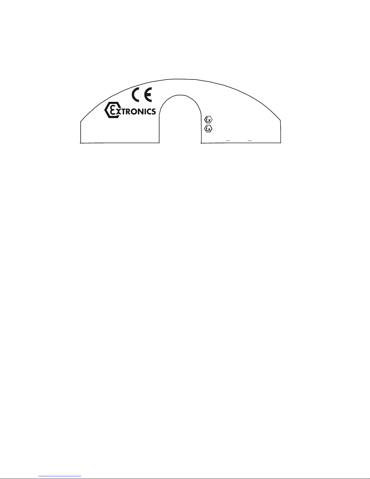
iScan 100
-30°C T +50°C
II 2 D T70°C
II 2 G EEx ib IIC T4
Serial no. : 269
Date: 26.03.2005
TÜV 04 ATEX 2644
RS-232, G + D
ATEX Label Format
additional electrical parameters see documentation!
GB-Congleton
1712
RS-232
< <
amb
31
Page 32

10 Booklet Revision Notes
First issue – Issue 1 – August 2007
32
 Loading...