

Page 1
Page 2
Please note: If you have received a paper copy of the instruction
guide, please contact CommBox Support for an electronic copy
of the guide. This will enable you to expand out the photos for
better recognition of Parts and Procedures.
Page 3
This Flat Panel Convertible Trolley has been designed as a generic
product and some of the fasteners, hol es and procedures may not
apply to your products individual needs. Mounting some of the items
to this product will require you to consult the manufactures instructions,
Do so accordingly!
During the build-up of the FPMC there are a number of areas that lifting of parts
etc can have adverse effects on personnel and parts if guidelines are not strictly
adhered to. Please read any Not es carefull y prior to completing each step.
During the engineering of this product ease of construction was our highest
priority. One of the steps taken was to use Cup Head Bolts, referred to as CHB.
The use of this fastening system enables construction with limited and basic
hand tools.
Read each step thoroughly prior to starting that step. If you have any questions
relating to the build-up of this product please contact your re-seller for
guidance.
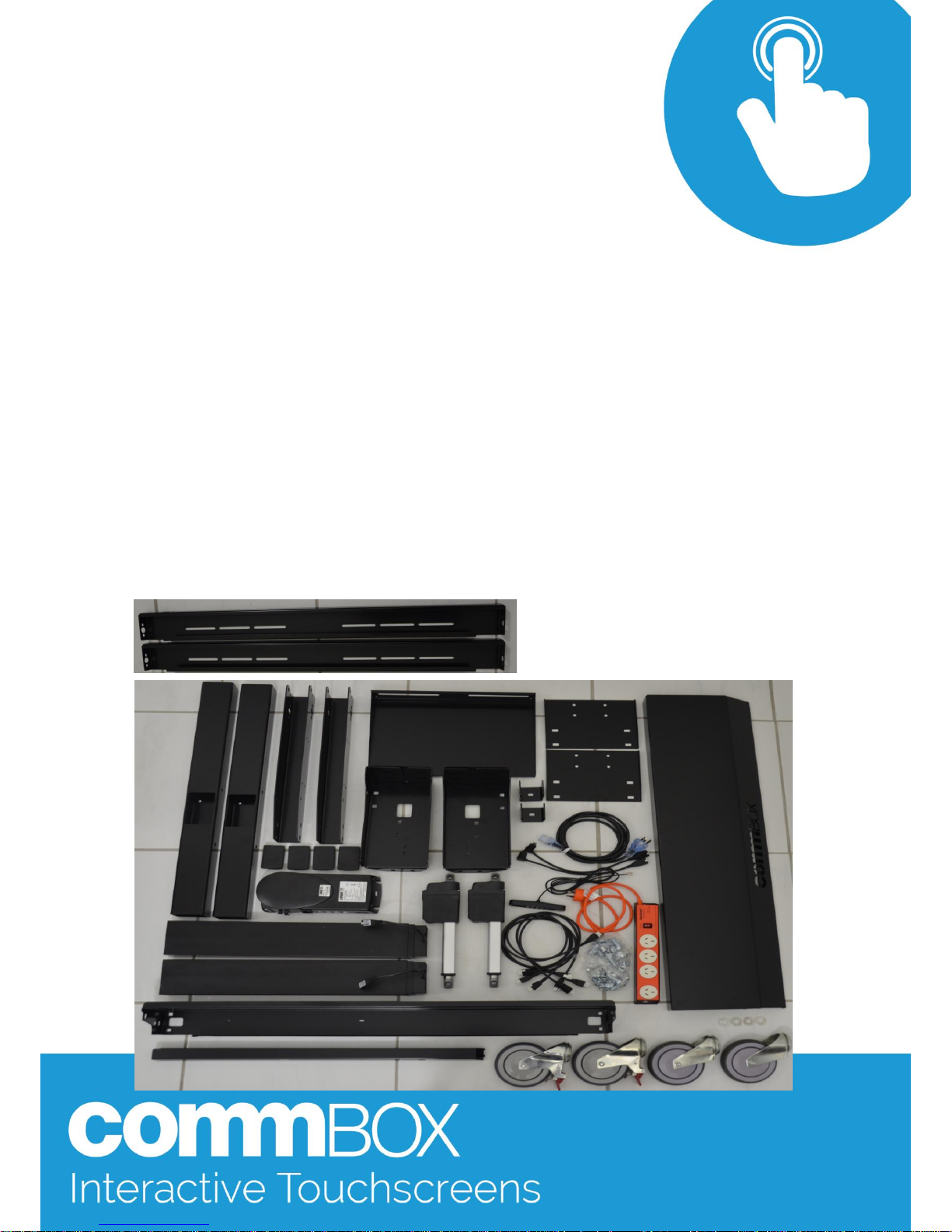
Parts Ident ification - All parts will be assigned a three digit number for ease of
identification. Ensure shipping box has arrived in serviceable condition. Open
box and remove all parts. Lay out for ease of identification. The breakdown of
the bolt pack contents is on the last page.
006
007
008
009
010
016
018
Page 4
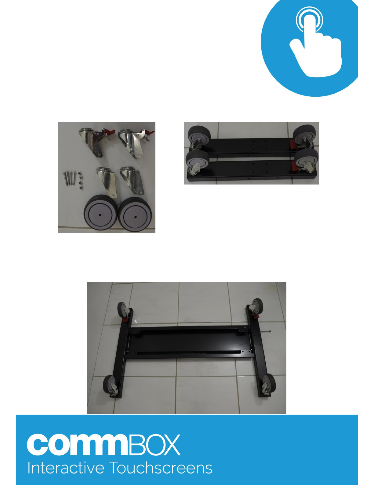
Step 1: Remove bolts from part 020 and using 4 12x30mm bolts and
12mm nyl ock nuts secure parts 020 to parts 001. Once castors are
secured, using a soft blow hammer, knock in the plastic end caps 008
into the ends of 001.
Note: the lockable castors go to the rear (short er end)
Step 2: Align parts 001 with 005 as shown. Using 4x 8x90mm bolts and 8mm nylock
nut s loosel y secure these parts.
Page 5
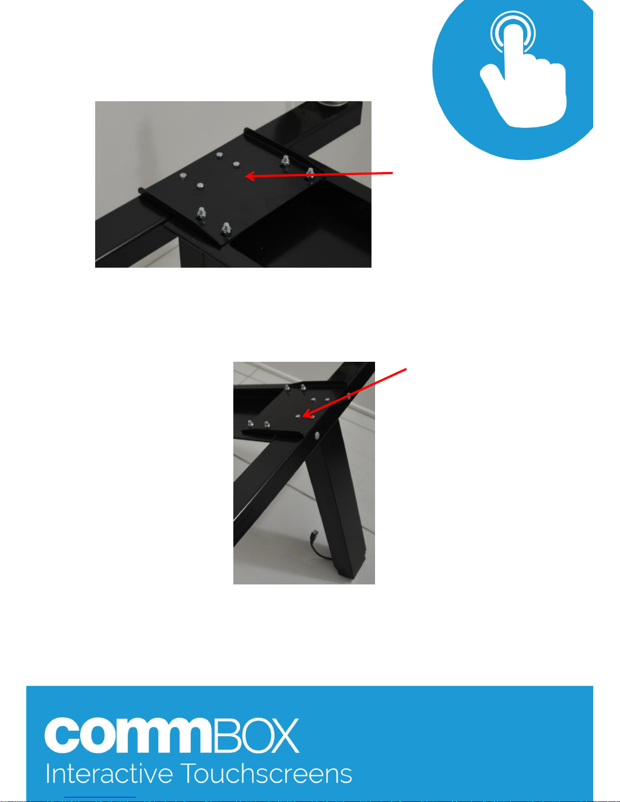
Step 3: Using 8 8x20mm CHB’s loosely secure parts 004 to 005
Step 4:
Minimum of two people required for this step
.
Aligning the cont rol cable of 013 to the inside, secure both col umns to the base
structure using 8x 6x25mm bolts.
4off 8x20mm CHB at each
end
4off 6x25mm Hex bolts
Page 6
Step 5: Once 01 3 are in position and tight, all remaining bolts can be tighten up.
There is a second mounting hole for the 8x20mm CHB from the side (higher than
shown here). The second 8x20mm CHB that secures the cable tray assembly is
shown below.
NOTE: The 8x20mm
CHB circled will
need to be fixed
through the hole
indicated by the
arrow, not as it is
shown
Step 6:
Page 7
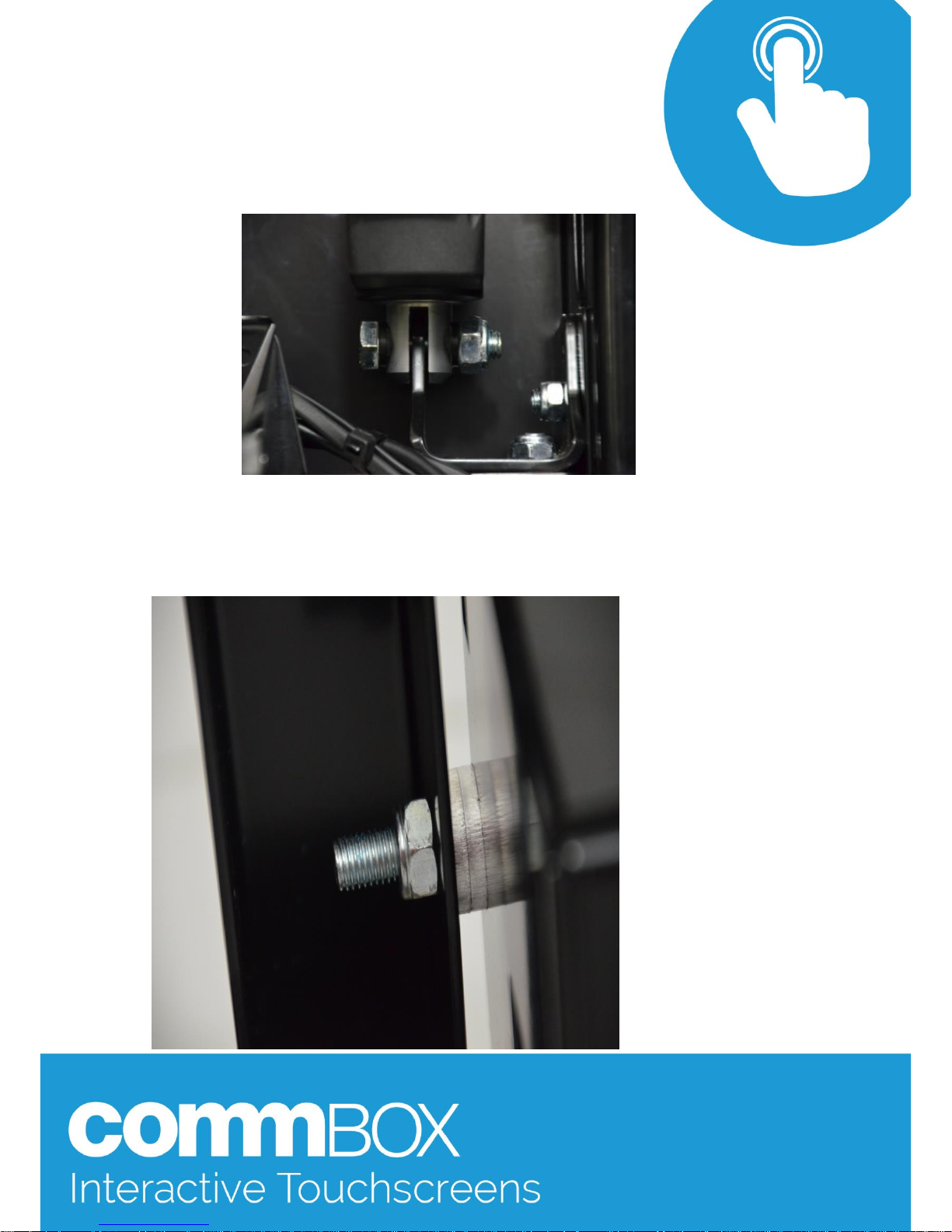
Step 7: Then push one 10x 40mm bolt in through the actuator and
part 007 as shown. Once all bol ts are in, secure the 8x20mm CHB’s
from Step 6. (do not over tight en the 10mm nut )
Step 8: Using parts 002, 018, one 10x 30mm CHB bolt & 10mm nyl ock nut per side
place two 018 washers bet ween parts 002 & 006. The bolt should be through the
upper hole on part 006, tighten the nut until firm.
Page 8
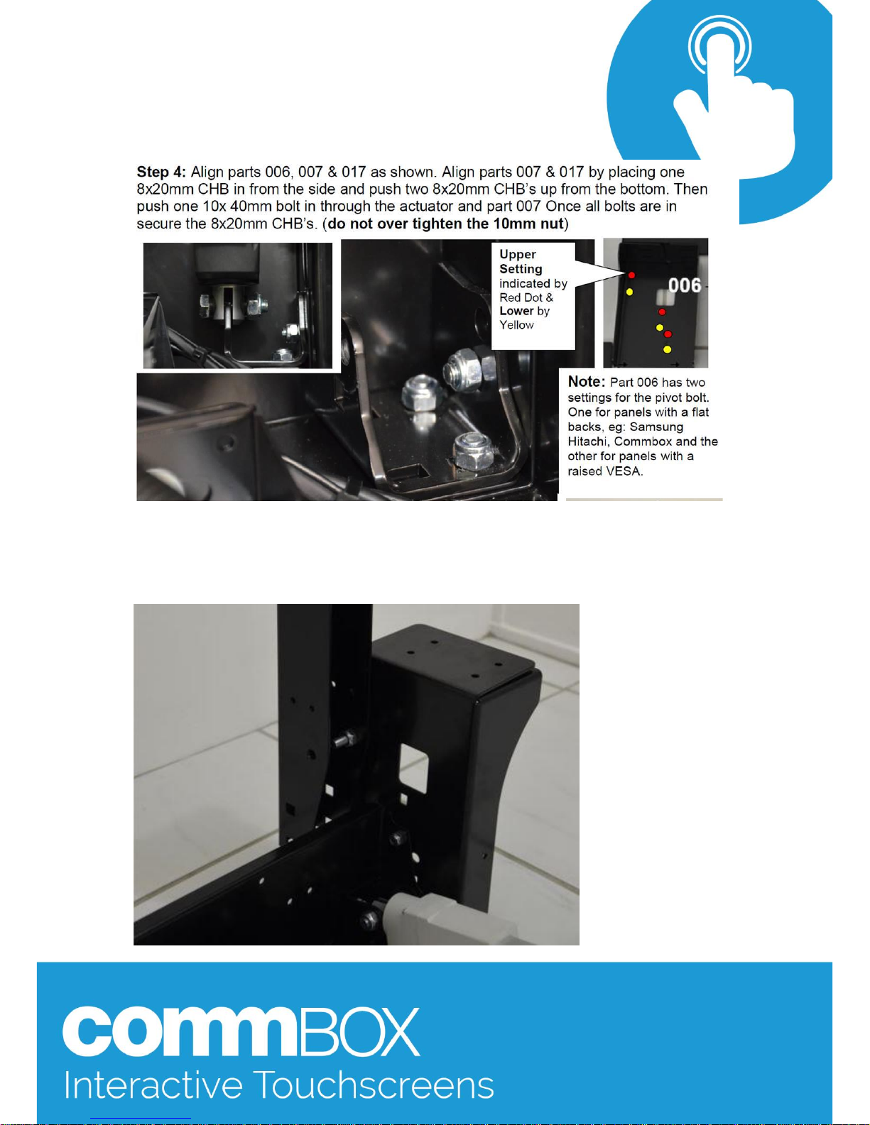
Step 9: Place the cable tray structure 006 onto the lift columns 013.
The fixing screws should be lined up as shown in the upper mounting position.
Page 9
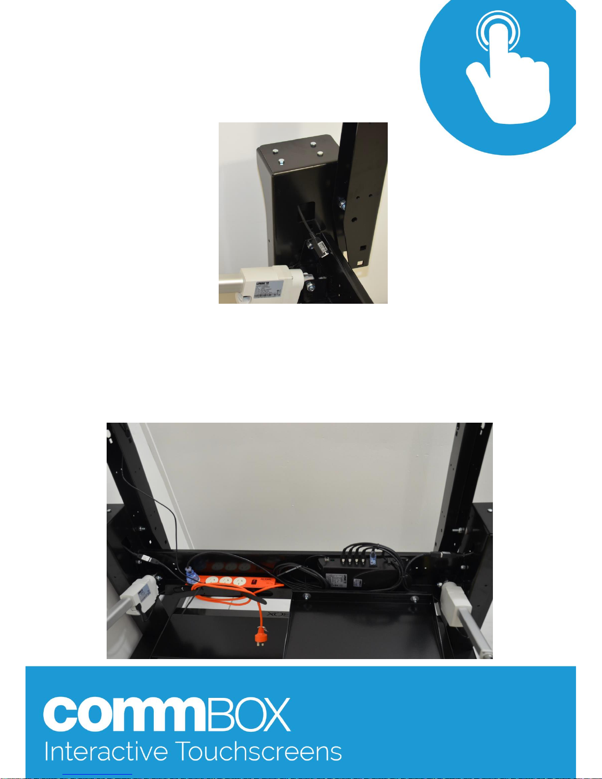
Ensure the columns cables are pushed through the large hol e in part s 006.
Step 9: Using 8 6x25mm bolts secure parts 006 to 013 (lift Columns) as shown above
Step 10: Using 4x1 2mm bolts and 4mm nylock nuts secure the control
box (part 010) to the cable tray 017.
Page 10
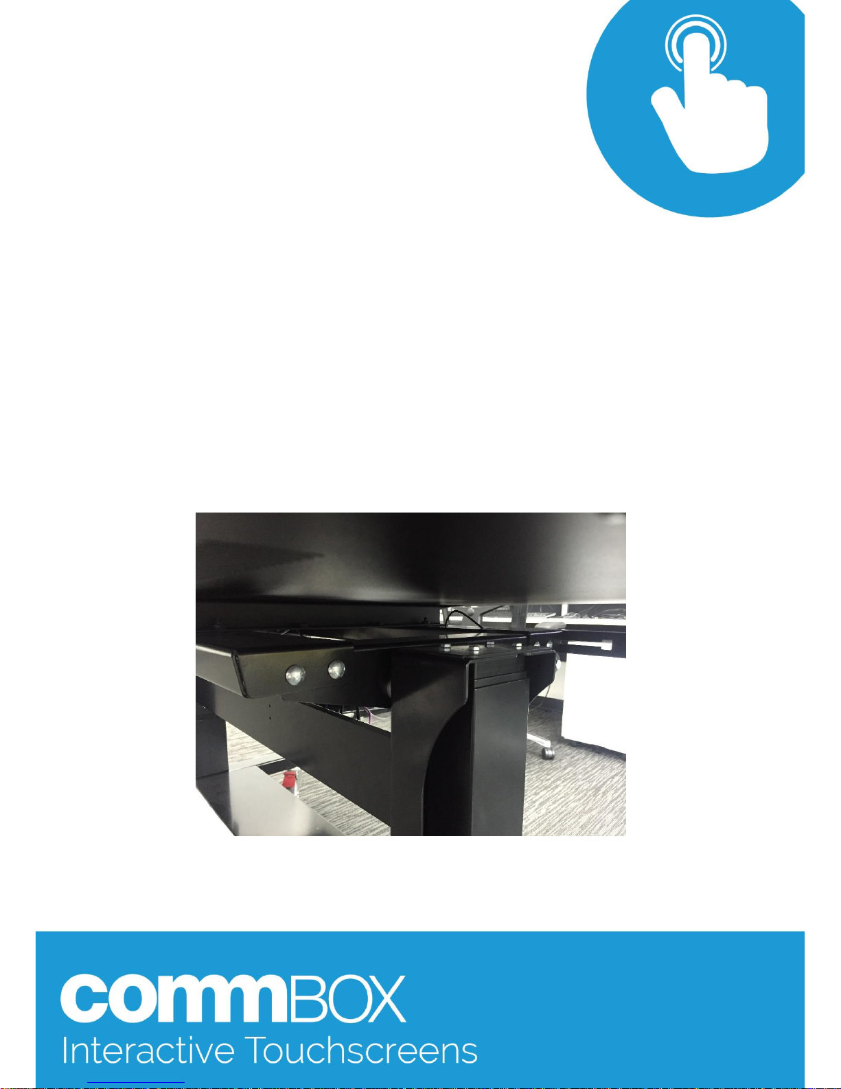
Step 11: Then secure part 015 (power board), using 4x8mm bolts and nylock nuts to
part 017.
Step 12: Secure part 003 (lap top tray) to part 017 using 2x 8x20mm CHB’s, 2x 8mm
washers and nylock nuts.
Step 13: Plug the actuator 013/ 011 extension leads into the actuator leads.01 3
actuators (column) plug into #1 & 2 on the control box. Actuators 011 (tilting) plug
into # 3 & 4.
NOTE: Please cable tie any leads after observing how much slack is required
during the operation of the trol ley. This will ensure not hin g is damaged during
normal operation.
Step 14: Bolt the 011 actuators to part 002 using 2off 10 x 65mm bol ts
and nylock nut s
NOTE: Do not over tighten these bolts. There wil l be some movement of the tilti ng
actuat or on this bol t during operation.
Page 11
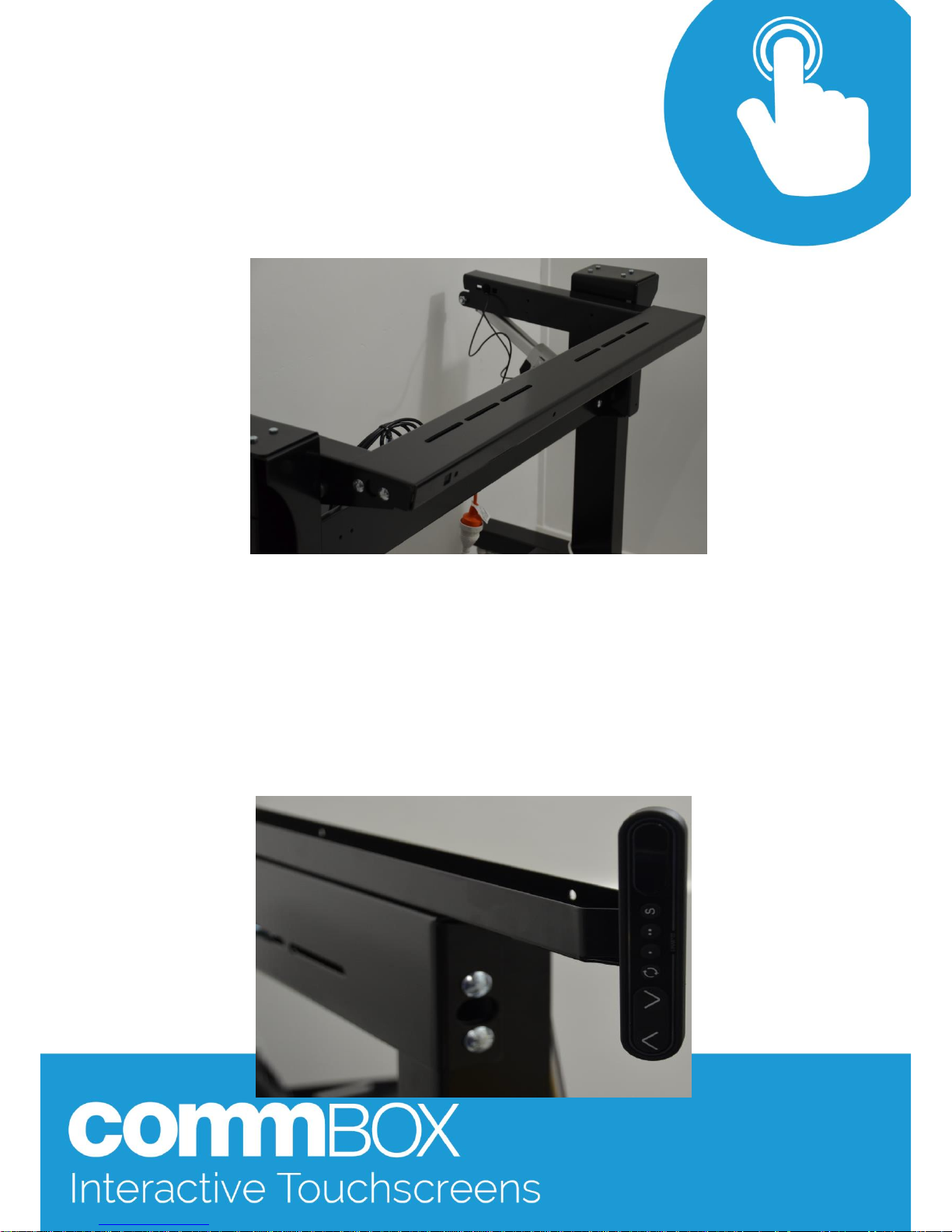
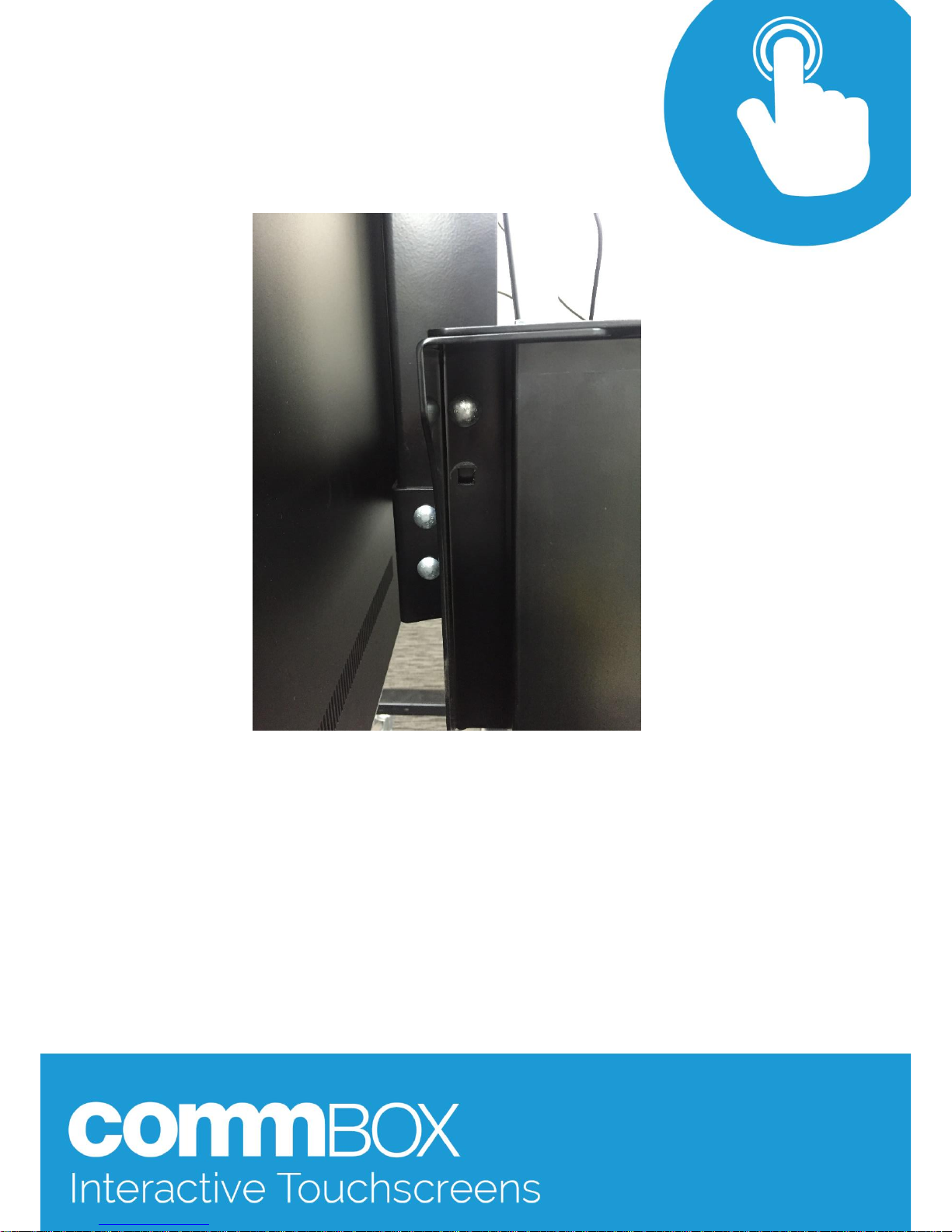
Step 15: Secure part 000 onto parts 002 using 4 8x20mm CHB’s (push bolts from the
outside towards the inside of the troll ey). This part must remain loose and movable.
To be secured during a later step.
NOTE: The 2 images above show the cradle mounted in the lower posit ion. The
cradle should be level wit h the vertical actuat ors
Step 16: Temporarily plug the Control Head into the powerboard.
Once it has been plugged in and all personnel, tools, cabling etc have
been secured and moved to a safe distance, maneuver the trolley down
using the LED cont rol head buttons. The rot ating arrows butt on changes
the control head from the Lift Columns to the Tilt Actuators.
Maneuver the Tilt Actuators to vertical prior to mounting the panel.
Page 12
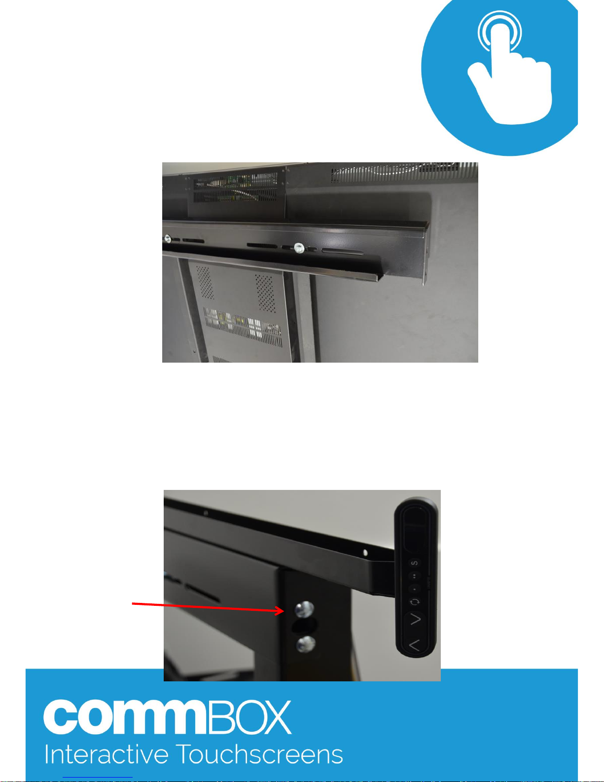
Step 16: Secure the remaining 000 bracket to the top row of the panel s VESA mount
using either the panel s supplied hardware or two of the 8x1 2/20mm bol ts and 8mm
washers.
Apply the foot brackets for the remainder of the assembly.
Step 17: Using a minimum of two people raise the panel and locate part 000
onto the cut-outs in parts 002.
Step 18: Using 4 8x20mm CHB’s secure the 000 bracket to parts 002.
Page 13

Step 19: Secure the remaining 2 8x12/ 20mm bolt s and 8mm washers into the
touchscreen’s lower VESA mounting hol es through the lower part 000.
Step 20: Tighten the 4 8x20mm CHB’s on the lower part 000
Step 21 : The actuators need to be init ialized to function correct ly.
Using the buttons shown above lower the touchscreen until it hits its lowest vertical
limit (indicated by a 1 on the LED screen on the control panel) . Continue to hold the
but ton down until the actuators move up slightl y.
Press the rotating arrow button and lower the touchscreen to the horizont al
position (indicated by a 2 on the LED cont rol panel). Continue to hold the button
down until the actuators move up slightly.
Once both steps are compl eted the trolley is ready to go.
Additional Notes
Transportation: When moving your tilt trolley around your campus, place the
touchscreen in the vert ical position and lower the touchscreen to within 1020mm of the castor legs (parts 001). Ensure al l leads are stowed safely and
out of the way of moving parts.
Safe Operation of the trolley: The Lift actuat ors have a built in safety feature
(Pizo) where any change in pressure between sides will automatical ly stop
and reverse the movement of the unit. This will also happen if the panel is
lowered onto the castor legs.
Error E01 : The E01 error will appear if the actuators get themselves out of
sync. If you get the E01 error fol low the initial ising procredure in step 20.
For any other errors please contact CommBox support on 02 9975 6001, or
alternatively you can log it through the website here.
 Loading...