

Page 1

• Thank you for purchasing COMMAX products.
• Please carefully read this User’s Guide (in particular, precautions for safety) before using a product and follow
instructions to use a product exactly.
• The company is not responsible for any safety accidents caused by abnormal operation of the product.
User Manual
WI -249LM / WI - 249LS
※ WI- 249LS
※ WI-249LM
• Thank you for purchasing COMMAX products.
• Please carefully read this User’s Guide (in particular, precautions for safety) before using a product and follow
instructions to use a product exactly.
• The company is not responsible for any safety accidents caused by abnormal operation of the product.
Page 2

1. Table of Contents
1. Table of Contents . . . . . . . . . . . . . . . . . . . . . . . . . . . . . . . . . . . . . . . . . . .1
2. Safety Warning & Caution . . . . . . . . . . . . . . . . . . . . . . . . . . . . . . . . . . . . .2
3. Parts and Description . . . . . . . . . . . . . . . . . . . . . . . . . . . . . . . . . . . . . . . .4
4. Product Concept . . . . . . . . . . . . . . . . . . . . . . . . . . . . . . . . . . . . . . . . . . .6
5. Main Device (WI-249LM) . . . . . . . . . . . . . . . . . . . . . . . . . . . . . . . . . . . . .6
6. Sub Device (WI-249LS) . . . . . . . . . . . . . . . . . . . . . . . . . . . . . . . . . . . . . .9
7. Specification and Features . . . . . . . . . . . . . . . . . . . . . . . . . . . . . . . . . . .12
1
Page 3

2. Safety Warning & Caution
Please follow the things described below in order to prevent any
danger or property damage.
P
rohibition.
I
Warning
Caution
t may cause a serious damage or
injury if violated.
I
t may cause a minor damage or
injury if violated.
No disassembly
N
M
Shows plugging out the power cord
without an exception
Shows the warning and caution for an electric shock.
Shows the warning and caution for a fire.
Warning
o touch
ust follow strictly.
Please don’t use several
products at the same time on
one power socket.
cause a fire due to an
It may
·
abnormal overheating.
Please don’
product in the place where
there is much oil, smoke or
humidity.
·
Power & Installation
t install the
It may cause an electric
shock or fire.
Please don’
t bend the power
cable excessively or it may
cause an electric shock.
fire when using a damaged
·
power cable.
Please don’t install the
product with the lightening
and thunder.
It may cause an electric
·
shock or fire.
Please don’
t handle the power
cable with a wet hand.
·
It may cause an electric
shock.
t use and connect
Please don’
this product with other
products with different rated
voltage
It may cause a disorder or
·
fire.
Please plug out the power
cable from the socket when
not using it for a long period
of time.
It may shorten the product
·
lifespan or cause a fire.
When installing the product
that generates heat, please
install the product away from
the wall (10cm) for the
ventilation.
·
It may cause a fire due to
the increased internal
temperature.
2
Page 4

P
lease don’tdisassemble,
repair or rebuild this product
arbitrarily (please contact the
service center if a repair is
n
eeded.
I
t may cause an electric
·
s
hock or fire.
Cleaning & UsePower & Installation
Warning
I
f an abnormal sound, burning
s
mell or smoke is coming out
o
f the product, please plug out
the power cable and contact a
service center.
It may cause an electric
·
shock or fire.
Caution
hock or fire.
t
insert any
P
lease don’
metallic or burnable materials
into the ventilation hole.
It may cause an electric
·
s
Please use only the designated
b
atteries for the products of
u
sing DC power.
I
t may cause an electric
·
shock or fire.
Please plug the power cable
firmly into the inner end
It may cause a fire.
·
Please be careful when using
an AC circuit breaker since
there is a possibility of an
electric shock.
When cleaning the product,
please rub it with a soft and
dry cloth after plugging out
the power cable. (Please don’
use any chemical products
such as wax, benzene, alcohol
or cleanser.)
Please hold the plug tightly
when unplugging the power
cable (a part of the copper
wire may be disconnected if
the grabbing is only made on
the cord when pulling out the
cable).
·
It may cause an electric
shock or fire
Please check the use voltage
and current for the DC-only
products and use the
appropriate rectifier.
·It may cause a fire.
Please don’
t drop the product
on the ground and don’
a shock .
t
·
It may cause a failure.
When connecting the power
cables after cutting the cable,
please install the product with
power off
·
It may cause an electric
shock or fire
Please avoid direct rays of the
sun or heating devices at a
time of installation.
It may cause a fire.
·
Please use the designated
connection cable within the
t apply
maximum calling distance
designated for the product
·
It may reduce the product
performance.
When installing the product,
please fix it firmly while using
the wall-mounting unit and
screws.
·It may cause an injury from
the falling object.
Please don’
product on an unstable place
or small support board.
It may cause an injury if it
·
falls down while in use.
t install the
Cleaning & Use
3
Page 5

3. Parts and Description
▶
▶
Main Device : WI-249LM
No.
1
2
3
4
5
Parts Name Parts Name
Microphone
Speaker
FND display
Paging button
Select button
No.
Power switch
6
Volume switch
7
DC adaptor input
8
9
Antenna
4
Page 6

▶
▶
Sub Device : WI-249LS
No.
1
2
3
4
Parts Name Parts Name
Microphone
Speaker
Paging button
Select button 8 Battery
No.
Power switch
5
Volume switch
6
DC Adaptor Input
7
8
Battery
5
Page 7

4. Product Concept
WI-249LM/S Devices are two-way wireless intercom system communicating via 2.4GHz frequency.
•
•
System Diagram
5. Main Device (WI-249LM)
•
•
Turning the power on
Connect 5.0V / 1A power adaptor to ⑧ DC adaptor input located on the side of WI-249LM.
Turn the ⑥
Display, a small dot LED is on to indicate the device is on.
•
•
Paring (Main / Sub devices)
The main device allocates a number to each sub device from number ‘00’ to ‘99’ when pairing. For
example, if you would like to allocate the number ‘03’ to a WI-249LS, use the ⑤
choose ‘03’ and press ⑦
When in pairing mode, two dot LEDs are blinking. When pairing is completed, ‘03’ disappears and a
double beep will sound. You can repeat the same method to pair all other sub devices with the main
device. Only the numbers between 00 and 99 are valid for allocation.
•
•
Paging Volume Adjustment
In standby mode, simply press the ⑦ Volume switch to adjust the paging volume. There are 3
levels (low-normal-high) of volume adjustments available and default is set as ‘normal’.
6
Power switch on located at the bottom of WI-249LM. At the right-lower side of FND
Select button to
Volume switch for 5 seconds to pair each other.
Page 8

Every time the volume switch is pressed, the volume level changes from normal → high → low →
normal → high in this order. If no input for 3 seconds, the device stores the last input value and
goes in to standby mode.
•
•
Call Volume Adjustment
While in talking mode, press the ⑦ Volume switch to adjust the call volume. There are 3 levels
(low-normal-high) of volume adjustments available and default is set as ‘normal’. Every time the
volume switch is pressed, the volume level changes from normal →
order. If no input for 3 seconds, the device stores the last input value and goes in to standby mode.
•
•
When Sub device (WI-249LS) Pages Main device (WI-249LM)
When a sub device (WI-249LS) pages the main device (WI-249LM), the seven-segment display on
the main device (WI-249LM) displays the ID number of the sub device (the number allocated to the
sub device from the pairing process). When paged, the display blinks repeatedly every 0.25
seconds.
•
•
When Main device (WI-249LM) Pages Sub device (WI-249LS)
Use the ⑤ Select button to choose a sub device you wish to page and press the ④ Paging button.
While paging, the display blinks repeatedly every 0.25 seconds. If the ④
without any sub device being selected, the sub device with the allocated number ‘00’ will be paged
(*** the main device WI-249LM can page any sub-devices only when the sub devices are
connected to DC power adaptor, not running on batteries).
•
•
To Hang Up the Call
Simply press the paging button once again to hang up the call. While in talking mode, the display
blinks repeatedly every 0.05 seconds.
high → low → normal → high in
Paging button is pressed
•
•
Time Limit for Paging Mode
Paging time is limited to 30 seconds. After 30 seconds, paging stops and the device goes in to
standby mode.
•
•
Time Limit for Talking Mode
Talking mode is limited to 3 minutes. After 3 minutes, the call is ended and the device goes in to
standby mode.
•
•
Pagine Tone
The paging tone is as follows :
Sol-Mi-Do Sol-Mi-Dol →
Sol-Mi-Dol →
•
•
Low Voltage Indication of Sub devices on the Main device display
If the sub devices (WI-249LS) are running on batteries and the batteries are low, the sub device will
send the low voltage information to the main device as paging the main device.
The FND display on the main device, after disconnecting with the sub device, displays the ID
Repeat until answered and/or stops paging after 30 seconds.
2 second pausel → Sol-Mi-Do Sol-Mi-Dol → 2 second pausel → Sol-Mi-Do
7
Page 9

number of the sub device in a blinking mode.
After replacing the batteries, you need to page the main device to register the new battery level
value and the main device must answer the call to register the new value.
•
•
Replacing a Sub device (WI-249LS)
If any of the paired sub devices is replaced, please try to use the same ID number of the removed
device to minimize the ID allocating processes.
•
•
Inverting the FND Display on Main device (WI-249LM)
Press ④ Paging button and ⑤ Select button simultaneously for 5 seconds to invert the displayed
number. This is useful when the main device is to be mounted on a wall or above the eye level
shelf.
•
•
Factory Default Setting (Initializing)
To initiate a factory default setting, first turn off the device using the ⑥ Power switch located at the
bottom of the device. Turn the power switch back on while pressing ④
button simultaneously. The display blinks repeatedly every 0.1 second to indicate the device is in
factory default setting mode. Press the ⑦
data including volume levels and pairing information is now deleted and set with factory default
setting.
•
•
Mute Mode
In standby mode, press ⑤ Select button for 5 seconds to deactivate the built-in microphone.
The device is now in mute mode. Repeat the same method to activate the microphone
•
•
SINGLE SPEED DIAL FUNCTION ON MAIN DEVICE (WI-249LM)
Without selecting any sub devices and directly pressing the paging button will page the sub device
with “00” ID number. If none of sub devices is being allocated with number “00”, the main device
does not page any devices.
Volume switch to initiate the factory default setting. All
Paging button and 5Select
8
Page 10

6. Sub Device (WI-249LS)
•
•
Turning the power on
There are two modes available to power on the sub devices.
AA Battery Mode
4 x AA size batteries are to be placed in WI-249LS and turn on the ⑤ Power switch.
5.0V / 1A Power Adaptor
When a DC power adaptor (5.0V / 1A) connected, the sub device recognizes it and automatically
goes in to a “constant power mode”, enabling the 2-way paging mode between main and sub
devices. Turn the power on by sliding the ⑤
•
•
Pairing (Main / Sub Devices)
A number between 00 and 99 must be allocated to each sub device WI-249LS. Turn the ⑤ Power
switch on and press ③
mode. The Red LED is blinking repeatedly every 0.5 seconds to indicate that the devices are in
pairing mode. A double beep sounds to indicate the pairing is completed. The pairing mode is
limited to 60 seconds.
•
•
Paging Volume & Call Volume Adjustment
Paging and Call volume of sub devices are adjusted simultaneously. The volume is to be adjusted
while in talking mode with the main device by pressing the ⑥
of the device. There are 3 levels (low-normal-high) of volume adjustments available and default is
set as ‘normal’. Every time the volume switch is pressed, the volume level changes from normal →
high → low → normal → high in this order. If no input for 3 seconds, the device stores the last input
value and goes back in to talking mode.
•
•
Time Limit for Paging Mode
Paging time is limited to 30 seconds. After 30 seconds, paging stops and the device goes in to
standby mode.
Paging button and ⑥ Volume button for 5 seconds to activate the paring
Power switch located at the bottom of the device.
Volume button located at the bottom
•
•
Time Limit for Talking Mode
Talking mode is limited to 3 minutes. After 3 minutes, the call is ended and the device goes in to
standby mode.
•
•
Paging Tone (WI-249LS)
The paging tone is as follows :
Sol-Mi-Do Sol-Mi-Do →
Sol-Mi-Do →
•
•
Line Busy Notice
If a sub device pages the main device while the main device is already in connection with another
sub device, a line busy tone sounds and the sub device goes back in to standby mode.
•
•
Factory Default Setting (Initializing)
To initiate a factory default setting, first turn off the device using the ⑤ Power switch located at the
bottom of the device. Turn the power switch back on while pressing ③
button simultaneously. The display blinks repeatedly every 0.1 second to indicate the device is in
Repeat until answered and/or stops paging after 30 seconds.
2 second pause → Sol-Mi-Do Sol-Mi-Do → 2 second pause → Sol-Mi-Do
Paging button and ④ Select
9
Page 11

factory default setting mode. Press the ⑥ Volume switch to initiate the factory default setting. All
data including volume levels and pairing ID number is now deleted and set with factory default
setting.
•
•
Red LED Indication When Paging
When paging, the Red LED blinks repeatedly every 0.25 seocnds.
•
•
Red LED Indication When Talking
When in talking mode, the Red LED blinks repeatedly every 0.05 seconds.
•
•
WI-249LS with Constant Power Supply (5.0V / 1A Power Adaptor)
When a DC power adaptor (5.0V / 1A) connected, the sub device recognizes it and automatically
goes in to a “constant power mode”, enabling the 2-way paging mode between main and sub
devices. If battery powered, the main device WI-249LM is not being able to page any sub devices
(Sub devices can page the main device), 1-way paging mode only.
•
•
Auto Call Accepting Mode
When sub devices are on a constant power mode (connected with 5V/1A power adaptor), press
4Select button for 5 seconds to activate the auto call accepting mode. If the main device pages the
sub device, the call is connected automatically without a paging sound and the time limit for talking
mode is now unlimited.
•
•
Factory Default Setting
To initiate a factory default setting, first turn off the device using the ⑤ Power switch located at the
bottom of the device. Turn the power switch back on while pressing Paging button and Select
button simultaneously. The display blinks repeatedly every 0.1 second to indicate the device is in
factory default setting mode. Press the Volume switch to initiate the factory default setting. All data
including volume levels and pairing ID number is now deleted and set with factory default setting.
•
•
Forced Voice Forwarding Function (PTT Mode)
WI-249LM/S devices are half duplex type which automatically determines the direction of audio
communication for effective sound quality by eliminating hauling and echo effects. If one side
creates a constant loud noise or talks loud constantly, the microphone on the other side is
deactivated at all times providing one sided communication. In this case, initiate a talk while
pressing the “Select button”. By releasing the Select button, the device is back to normal talking
mode.
•
•
Repeater
This is an optional mode for a sub device, WI-249LS.
After registering main and sub devices to a repeate, the communication is now enabled only
through the repeater. It means if the repeater is turned off, the registered devices cannot
communicate each other.
•
•
Repeater Setting
Connect 5V / 1A DC power adaptor to WI-249LS. By pressing the ④ Select button and ③ Paging
10
Page 12

button simultaneously for 5 seconds, you can turn the sub device into a repeater mode. The Red
LED blinks every 1 second to indicate a repeater mode. To turn the power off, use the ⑤
switch at the bottom of the device. Repeater mode is enabled only if a constant power is supplied
by a power adaptor (5V / 1A DC power adaptor).
•
•
Pairing (Main WI-249LM/Repeater)
Press the ⑥ Volume switch on a repeater for 5 seconds to go in to pairing mode. The Red LED
blinks every 0.5 seconds to indicate that the repeater is in pairing mode. A sound of a double beep
indicates the pairing is completed. The pairing mode lasts for 60 seconds.
•
•
Paring (Repeater/Sub WI-249LS)
Press the 3Paging switch on a repeater for 5 seconds to go in to pairing mode. The Red LED blinks
every 0.5 seconds to indicate that the repeater is in pairing mode. A sound of a double beep
indicates the pairing is completed. The pairing mode lasts for 60 seconds.
Repeat the same method if more than one sub devices are to be paired with the repeater.
•
•
Red LED Indication When Setting Up a Repeater.
Red LED blinks every 1 second if the sub device is in Repeater mode.
•
•
Red LED Indication When Main Pages Sub Device
Red LED blinks every 0.05 seconds if the Main device pages sub devices including ones not paired
with a repeater.
•
•
Red LED Indication When Sub Pages Main Device
Red LED blinks every 0.05 seconds if the Sub device pages main device.
Power
•
•
Factory Default Setting
To initiate a factory default setting, first turn off the device using the 5Power switch located at the
bottom of the device. Turn the power switch back on while pressing Paging button and Select
button simultaneously. The display blinks repeatedly every 0.1 second to indicate the device is in
factory default setting mode. Press the Volume switch to initiate the factory default setting. All data
is deleted and set with factory default setting.
11
Page 13
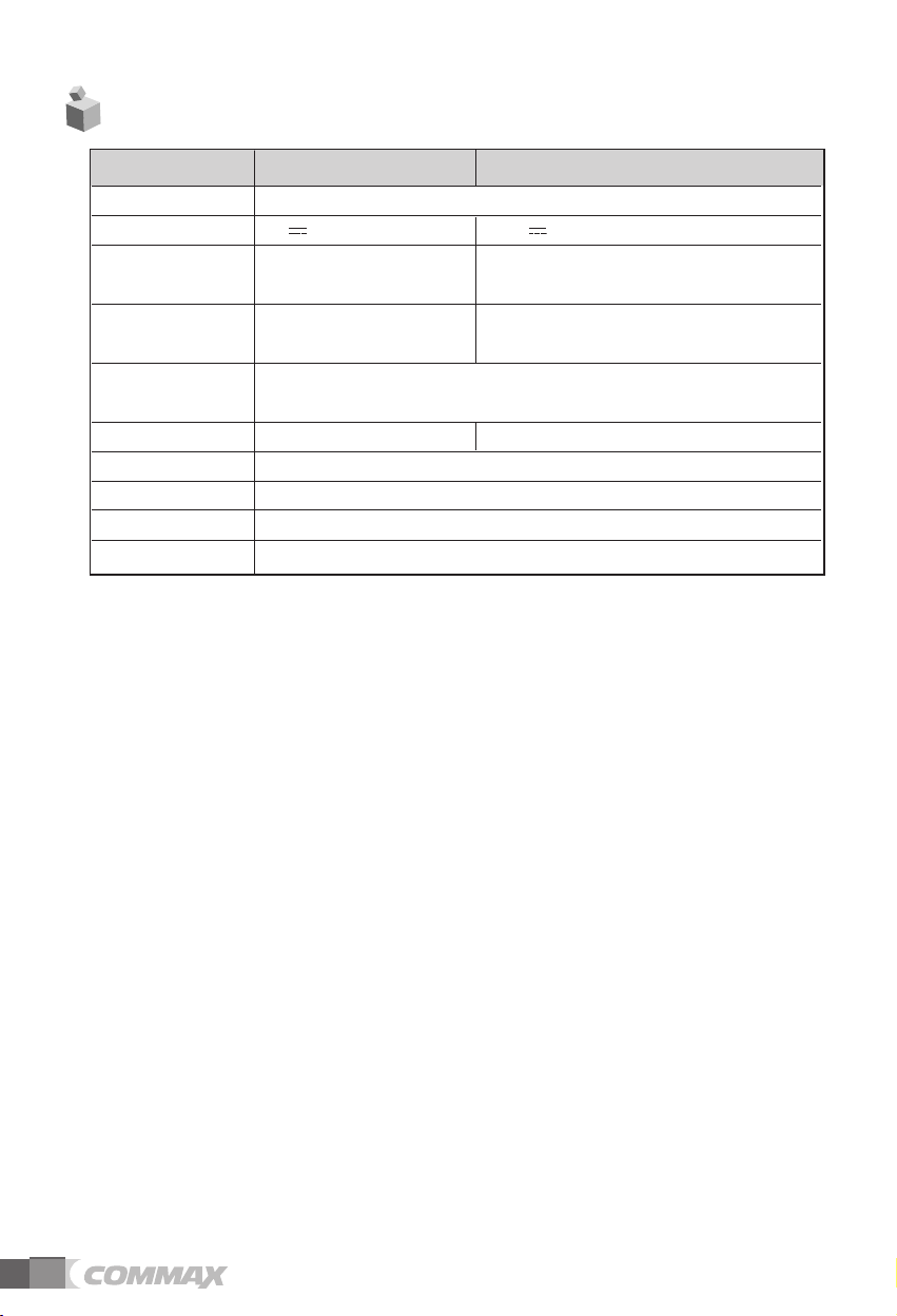
7. Specification and Features
Model WI-249LM WI-249LS
Call Method GFSK
Power Source 5V , 1A 5V , 1A or or AA Alkaline Battery 4EA
Standby
Consumption
Power
Communication
Communication
Method
Display FND LED
Ring tone Chime
Distance Open area : 200M, Indoor : 40~50M
Temperature 0 ~+40℃ (32℉ ~ 104℉)
Dimensions 140(W) X 72(H) X 88(D)
•
•
It is likely to be affected by surroundings. Call quality may be poor, if it is affected by Elevators,
high voltage, Radio Frequency Interference and iron doors.
0.8W 0.8W(Adaptor)
1.4W 1.2W
HANDS FREE (half duplex)
12
Page 14

513-11, Sangdaewon-dong, Jungwon-gu, Seongnam-si, Gyeonggi-do, Korea
Int’l Business Dept. Tel. : +82-31-7393-540~550 Fax. : +82-31-745-2133
Web site : www.commax.com
PM18249LMS10
Printed In Korea / 2014.04.104
 Loading...