

Page 1

<,,,
SECURITY.
DOOR PHON
..
SYST·EM
INSTRUCTION
FOR
USE
DP-2T
E
I
JJM-DP2T-001
Printed
in.
Korea ·
JUNG
~..:-
ANG
@
ELECTRONICS CO., LTD.
Page 2

• INTRODUCTION
• FEATURES
Congratulation
Please read these instructions carefully before installing
all
of
the directions to ensure proper installation.
This instruction manual explains
your new security system
• PARTS CHECKLIST
Room Station
Mounting Bracket
Mounting Screws
Magnetic Switchs
Door station
on
the purchase
of
your new Security Doorphone System!
in
simple steps how to install, use
in
homes, offices or businesses.
'1
1
8
1
1
~
I
"""'
Mounting Bracket
your;
system and follow
.•
and care for
'' ''
''''
Screws
ROOM STATION
3
7
1.
Handset
Lift to communicate with your visitor.
2. Theft Enunciator Device
Sounds Alarm if the invader comes in.
3.Hook
Choose operation or stand-by mode
by handset.
4. Security Lamp
See set security mode.
5. Security Button
Push to set security mode.
6. Door Release Button
Releases the door to let your visitors
in
·after checking them.
DOOR STATION
Speaker---,
Mounting
Bracket
10
5
7.
Call Sound Volume
Permits the adjustment
sound volume.
8. AC Power cord
Plugs the room station
outlet.
9.
Terminal A
connection to the electric door
opener.
1
0.
Terminal B
Connection to the door station.
11. Terminal C
connection to the magnetic switch.
of
in
to the AC
Figure 2
the call
EfiDJ
~
Magnetic Switch
Door Station
Figure 1
Call Button
Microphone
Screw-·-
•---
Junction
Terminal
Ill
•lai!Go
Figure 3
Page 3
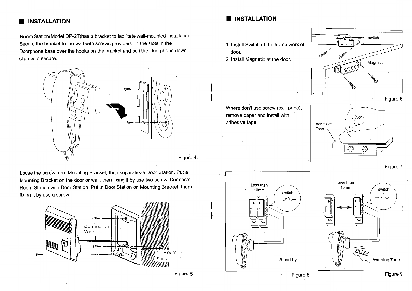
• INSTALLATI'ON
Room Station(Model DP-2T)has a bracket to facilitate wall-mounted installation .
in
. Secure the bracket to the wall with screws provided. Fit the slots
Doorphone base over the hooks on the bracket and pull the Doorphone down
slightly to secure.
e--
the
1
• INSTALLATION
1.
Install Switch at the frame work
door.
2.
Install Magnetic at the door.
of
/
c/
"",
"",
""•
Figure 4
Loose the screw from Mounting Bracket, then separates a Door Station. Put a
Mounting Bracket on the door or wall, then fixing it by use two screw. Connects
in
Room Station with Door Station. Put
fixing it by use a screw.
Door Station on Mounting Bracket, them
l
J
I
Where don't use screw
remove paper and install with
adhesive tape.
(ex:
Figure 6
pane),
Adhesive
Tape
@ @
Figure 7
over than
10mm
Figure 5
Stand by
Figure 8
~
~
Warning Tone
Figure 9
Page 4
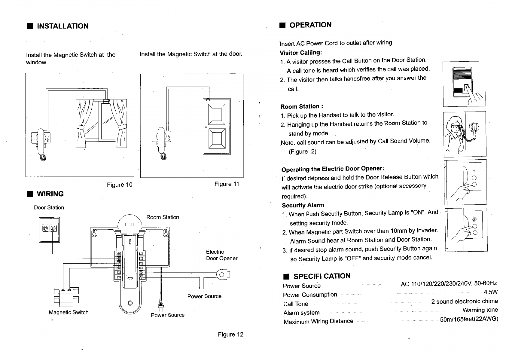
• INSTALLATION
Install the Magnetic Switch at the
window.
Figure 10
• WIRING
Door Station
~~
Install the Magnetic Switch at the door.
~
og
Figure
Electric
Door Opener
11
• OPERATION
Insert AC Power Cord to outlet after wiring.
Visitor Calling:
1.
A visitor presses the Call Button on the Door Station.
A call tone
2.
The visitor then talks handsfree after you answer the
call.
Room Station :
1.
Pick up the Handset to talk to the visitor.
2.
Hanging up the Handset returns the Room Station to
stand by mode.
Note. call sound can
(Figure
Operating the Electric Door Opener:
If desired depress and hold the
.
will activate the electric door strike (optional accessory
required).
Security Alarm
1.
When
setting security mode.
2.
When Magnetic part Switch over than 1
Alarm Sound hear at Room Station and Door Station.
3.
If desired stop alarm sound, push Security Button again
so Security Lamp
is
heard which verifies the call was placed.
be
adjusted by Call Sound Volume.
2)
Door
Release Button which
Push
Security Button, Security Lamp
is
"OFF" and security mode cancel.
Omm
is
"ON". And
by invader.
Magnetic Switch
Power Source
Power Source
Figure 12
• SPECIFI CATION
Power Source
Power Consumption
Call Tone
Alarm system
Maximum Wiring Distance
AC
11
0/120/220/230/240V, 50-60Hz
2 sound electronic chime
50m/165feet(22AWG)
4.5W
Warning tone
 Loading...