

Page 1
User Manual
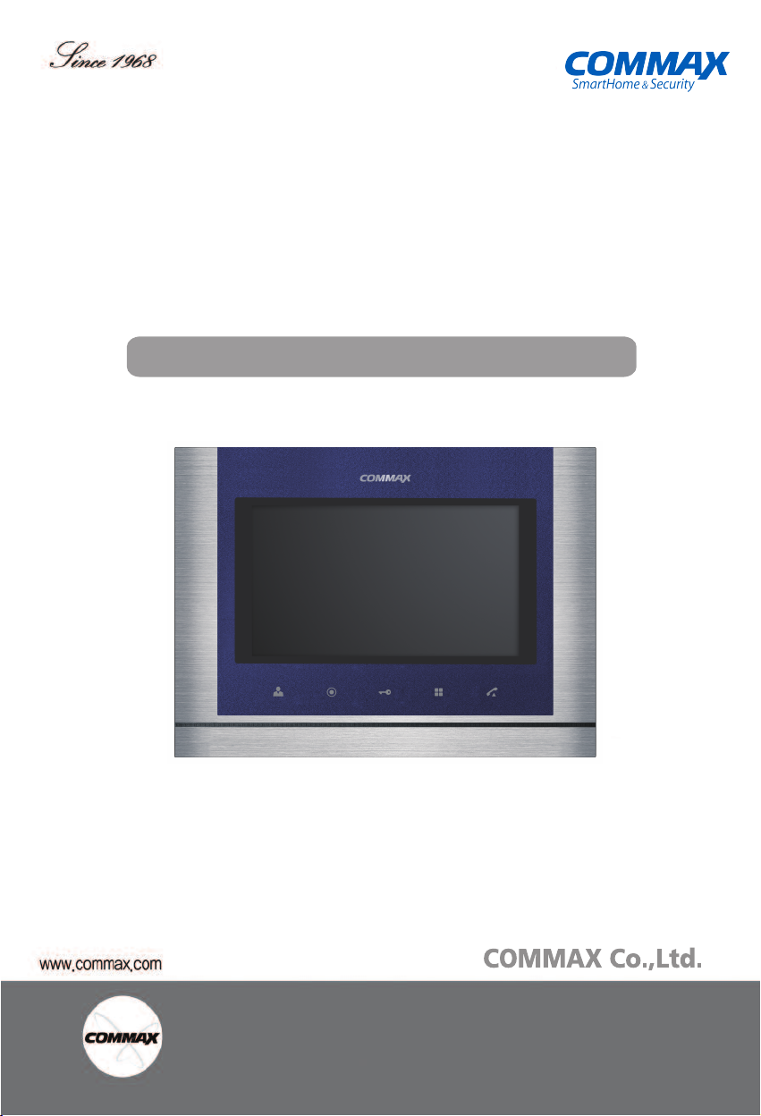
Color Video Door Phone CMV-70M / CMV-70MD
� Thank you for purchasing COMMAX products.
•Thank you for purchasing COMMAX products.
� Please carefully read this User’s Guide (in particular, precautions for safety) before using a product and follow
•Please carefully read this User’s Guide (in particular, precautions for safety) before using a product and follow
instructions to use a product exactly.
instructions to use a product exactly.
� The company is not responsible for any safety accidents caused by abnormal operation of the product.
•The company is not responsible for any safety accidents caused by abnormal operation of the product.
Page 2
T
able of Contents
1. Warnings and Cautions...........................................................................2
2. Part Names....................................... .............................
3. Package Contents .................................................................... ............3...
4. Installation................................................................................... ..........4.....
5. Wiring. ........................................... ..............................................
Operation .....................................................................................................
6.
... ........4...
7. Settings .................................................................................... .............9....
...............118. Specifications..........................................................................
3............................
5
1. W
arnings and caution
Please follow the things described below in order to prevent any
danger or property damage.
Prohibition.
Warning
Caution
Please don’t disassemble,
repair or rebuild this product
arbitrarily (please contact the
service center if a repair is
needed.
·It may cause an electric
shock or fire.
It may cause a serious damage or
injury if violated.
It may cause a minor damage or
injury if violated.
W
If an abnormal sound, burning
smell or smoke is coming out
of the product, please plug out
the power cable and contact a
service center.
·It may cause an electric
shock or fire.
No disassembly
No touch
Must follow strictly.
Shows plugging out the power cord
without an exception
Shows the warning and caution for an electric shock.
Shows the warning and caution for a fire.
arning
Please don’t insert any
metallic or burnable materials
into the ventilation hole.
·It may cause an electric
shock or fire.
Please use only the designated
batteries for the products of
using DC power.
·It may cause an electric
shock or fire.
Cleaning & Use
2
Page 3
Warning
Please don’t use several
products at the same time on
one power socket.
·It may cause a fire due to an
abnormal overheating.
Please don
’t install the
product in the place where
there is much oil, smoke or
humidity.
·It may cause an electric
shock or fire.
Power & Installation
Please don’t bend the power
cable excessively or it may
cause an electric shock.
·fire when using a damaged
power cable.
Please don’t install the
product with the lightening
and thunder.
·It may cause an electric
shock or fire.
Please don’t handle the power
cable with a wet hand.
·It may cause an electric
shock.
Please don’t use and connect
this product with other
products with different rated
voltage
·It may cause a disorder or
fire.
Please plug out the power
cable from the socket when
not using it for a long period
of time.
·It may shorten the product
lifespan or cause a fire.
When installing the product
that generates heat, please
install the product away from
the wall (10cm) for the
ventilation.
·It may cause a fire due to
the increased internal
temperature.
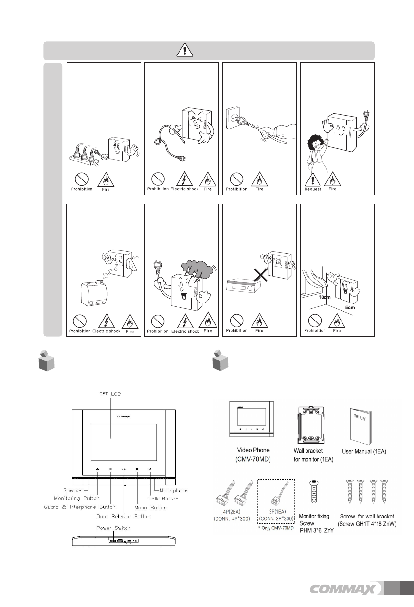
2. Part Names
3. Package Contents
3
Page 4
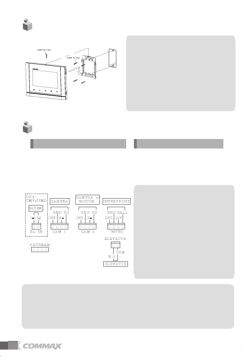
4. Installation
5.Wiring
▷
▷
Polarity of the camera connector
1. Red: Talk (Audio)
2. Blue: GND
3. Yellow: Power (+12V)
4. White: Video
Note
•
Avoid installing the product in
the area of direct sunlight.
•
The position of the unit's body should
fit the standard height range
(Recommended height range is
1450 ~ 1500mm.)
•
Avoid installing the product exposed to
gas exposure, magnetic force,
in humid temperatures, as it may
damage the condition and
performance of the product.
▷
▷
Polarity of interphone connector
1. Red: Talk (Audio)
2. Blue: GND
3. Yellow: Power (+14V)
4. White: Call signal
If you connect with MODUM system, you need
to connect with 'CAMERA2' ports and
floor distributor(Please refer to the manual of
floor distributor for wiring.)
Warning :
-
If you connect with a floor distributor(to connect
with lobby or guard station), you have
to connect with only 'CAMERA2' port.(If you
connect with 'CAMERA1' port and floor
distributor, it will not be operated normally.
- Do not use it with other devices when you use it
with floor distributor, other devices,
When the system power cut off in case of blackout,
each device can't be recognized to
each other because of communication problem.
In this case, re-boot the Video-phone.
※
Note
1. In case, if there is a high-voltage power line in the area of installation, use metal tube
coaxial cable for wiring
2. Beware of wrinkling of line coating and cable stick-outs as it may cause circuit shortage
and
operation
inconvenience.
3. When connecting a monitor with a camera, make sure power switch is turned off.
4
Page 5

. Operation
6
6-1
Functions for single & MODUM system
6-1-1
Use for single system
1) Communicate with visitor
(1) Communicate in Monitor
① As the paging button on a door camera is pressed, the paging tone rings at the
connected videophone and the visitor’s figure appears on the monitor.
②
Press 'Talk' button to talk to the visitor and “Door release” button to open the door.
(The door release function is enabled only when the screen is turned on and the
individual door camera has door release terminal)
③ If an other visitor calls fro m anoth er e ntrance during a c all, th e first ca ll i s
automatically ended and the connection to another entrance is made.
④
Press the 'Talk' button to finish the communication and convert to the standby
(2) Communicate with additional interphone
① As the paging button on a door camera is pressed, the paging tone rings at the
interphone and videophone at the same time.
② Pick up the hand-set to start talking with a visitor, and to release the door for
pressing Door release button.
(The door release function is enabled only when the screen is turned on and the
individual door camera has door release terminal).
mode.
2) Communication between the monitor and interphone
(1) Monitor ➔ Interphone
① Press the “Guard and interphone” button in the monitor, the paging tone rings at the
interphone.
② Pick up the handset to start communicating with interphone.
③
Press 'Talk' button to finish the communication and convert to standby mode.
(2) Interphone ➔ Monitor
①
Pick up the hand-set and press the 'Call' button, the paging tone rings at
②
Press 'Talk' button on the monitor to start communicating.
③ Hang off the hand-set to finish the communication and convert to standby mode.
3) Monitoring
① Press the “Monitoring button” in standby mode, you can check the image in order.
- Camera 1 → Camera 2 → OFF → Camera 1 → repeat
②
Press 'Talk' button during monitoring to call to the entrance.
the monitor.
5
Page 6

6-1-2
Use for MODUM system
- This function is only for MODUM system.
- If the MODUM system is connected, it is automatically recognized when it boot.
Please reboot the power after installation for stable operation.
Communicate with visitor
1)
(1) Paging from a common entrance
① When a visitor page from a common entrance, the paging tone rings and the visitor’s
figure appears on the monitor.
②
Press 'Talk' button to talk to the visitor and “Door release” button to open the door.
(The door release function is enabled only when the screen is turned on.)
③ If another visitors calls from an individual entrance, the paging tone rings and press
“Monitoring” button to receive a call from the individual entrance after finishing the
communication with a common entrance.
④
Press 'Talk' button to finish the call and convert to standby mode.
(2) Paging from an individual entrance
- Same as the Single system mode.(Except interphone related information)
- The paging tone rings when it is received a paging from a common entrance or guard
station while talking with the individual entrance. Press “Guard and interphone” button
to connect after finishing communication with the individual door unit.
2) Communication with a guard
(1) Receive a call
① The paging tone rings when receive a call from guard station.
②
Press 'Talk' button to communicate.
③ When it receive any paging from an individual door camera, the paging tone rings and
press “Monitoring” button to receive a call from the individual door camera after
finishing the communication with a guard station.
④
Press 'Talk' button to finish the communication and convert to standby mode.
(2) Make a call
- The following menu appears on the right-lower corner when “Guard and interphone” button is
pressed in standby mode.
- For paging “Porter”, press “Monitoring” button while the menu is displayed on the screen.
: The call is connected if PORTER receives it.
- For paging “Guar d ” , p r e s s
displayed on
Press 'Talk' button if you don’t
the screen.
“Guard and interphone” button
: The call is connected if the
make a call.
guard receives it.
while the menu is
-
6
Page 7

3) Monitoring (Individual entrance / Common entrance / CCTV)
- The following menu will be appeared on the right-lower corner when press the “Monitoring”
button in standby mode.
- Press “Monitoring” button to monitor the individual entrance when OSD menu displays on
screen.
- Press “Guard and interphone” button to monitor the common entrance when OSD menu
appears on screen.
: Press 'Talk' button to make a call while monitoring the individual and common entrance.
Press 'Talk' button to finish the menu.
- Press “Door release” button to monitor CCTV when OSD menu appears on screen.
: When the CCTV monitoring mode is selected, the additional select menu displays on
screen. Press 'Talk' button to finish it. (Refer to description below to select CCTV for
monitoring.)
- Additional CCTV selection menu
7
Page 8

(1) When 1 unit of CMD-104VU is installed,
: Ports number 1 to 4 will be shown on screen and press each port number that will be
displayed on the screen.
: Port number that is displayed on the screen depends on the setting of DIP S/W of
104VU.
CMD-
(2) When 2 units of CMD-104VU are installed
(If port number 1-2 is connected, only no. 1 and 2 will be displayed)
: The ▷ mark will be shown with port number and you can move on the next page. (Up to 8
ports, No. 1-8)
: According to ID setting of CMD-104VU, ID 1 of CMD-104VU will be connected with port
No. 1 ~ 4, ID 2 of CMD-104VU will be connected with port No.5 ~ 8.
NOTE
1. You can check the other CCTV screen pressing other numbers while you are monitoring.
(If you press the same button that you have already monitored, monitoring will be finished
and convert to standby mode.)
2. You can select up to 8 CCTV, and available quantities are automatically recognized and
displayed on screen.
8
Page 9

4) Page the elevator
- If the elevator is connected with monitor, you can use this function.
- In the standby mode, if you press the “Guard & Interphone” button, the additional menu will
be displayed at the lower-right corner of screen.
- For paging elevator, press the door release button while the menu is displayed.
- When you page the elevator, “EVL CALL” message will be displayed at the top of screen.
- After paging the elevator, the screen will be back to the standby mode.
- If you don’t page the elevator, press the 'Talk' button.
7. Settings
- Press “Menu” button in video call or monitoring mode then Setting OSD will be
shown on screen.
- After Menu screen appears, you can change setting with below 4 buttons
Menu start and finish :[ ] (Menu button -‘[ ] ’)
select and input : [ ] ( Interphone button-‘[ ] ’)
Move upward /move right : [ ] (Door release button –‘▲’ / ‘▶’)
Move downward /move left : [
] ( Monitoring button–‘▼’ / ‘
◀’ )
9
Page 10

- OSD will be changed as below when select any menu.
DOOR VIDEO SET (Control the display)
7-1
1) BRIGHTNESS : select 0~20, defaults 10
2) CONTRAST : select 0~20, defaults 10
3) COLOR : select 0~20, defaults 10
- Settings for Brightness / Contrast / Color
(1) Use “Move” key to go to the each section
(2) Press “Select” key to activate the section(Move to the select window)
(3) Use “Move” key to adjust the level from 0 to 20.
(4) After adjustment, press “Select” key to go back to menu.
4) RESET : Reset Brightness / Contrast / Color.
Press “Select” key and select YES. And then press “Select” key again to reset.
5) EXIT : Press “Select” key to go back to setting menu.
UTILITY(Set the volume and screen ratio)
7-2
1) CHIME-BELL VOLUME : Adjust the chime-bell volume when it receives the paging.
- Adjust from 0(MUTE) to 3(MAX).
2) SPEAKER VOLUME : Adjust the speaker volume while calling.
- Adjust from 1(MIN) to 3(MAX).
3)
SCREEN MODE: Setting image’s ratio on the screen.
※ Setting
- ZOOM : 4: 3 ratio’s image is enlarged to fill the screen. (defaults value)
- 4:3 : the actual ratio of the image from camera.
- WIDE : 16:9 ratio’s image is enlarged to fill the screen.
4) EXIT : Press “Select” key to go back to setting menu.
10
Page 11

7-3
INFORMATION (Check product name and version)
1) MODEL : It means model name
2) VERSION : It means product’s version.
3) SYSTEM : SINGLE (It works as CDV mode)
or HOME ID : When it works as system mode(MODUM). It marks building, room number.
4) VIDEO : It expresses that Current method of image(NTSC/PAL) and version.
5) SOURCE : It expresses that current image’s position
6) Touch : Display the touch key version.
EXIT
7-4
- Using the move buttons to “Exit” menu and finish the setting
8. Specifications
pe
W
irin
g ty
Power Source
Power Consumption
Communication method HANDS FREE type (Voice switch circuit)
Monitor 7″ TFT-DIGITAL LCD
Ringtone
Image transmitting time Monitoring : 30 ±5sec , Communication : 60 ±5sec
Max. Distance(UTP)
Operating Temperature
Reference : Design and functions of the product are a subject of constant
development as a pursuit of quality improvement
Camera 4-wire (Polarity, CAM2 will be convertible with
MODUM system) Inperphone 4-wire (Polarity)
CMV-70M : 100-240V,50/60Hz(FREE VOLTAGE)
CMV-70MD : 24 ,1A
Stand by : 4 W Max : 15 W
- Individual entrance: Electronic chime with 3 tones
(for 2 consecutive times)
- Guard : Melody chime
- Interphone : Electronic bell
28m(0.5mm) / 50m(0.65mm) / 70m(0.8mm)
0 ~ +40℃ (32°F ~ 104°F)
11
Page 12

513-11, Sangdaewon-dong, Jungwon-gu, Seongnam-si, Gyeonggi-do, Korea
Int’l Business Dept. Tel. : +82-31-7393-540~550 Fax. : +82-31-745-2133
Web site : www.commax.com
PM5470S00010
Printed In Korea / 2015.03.104
 Loading...