

Page 1

• Thank you for purchasing COMMAX products.
• Please carefully read this User’s Guide (in particular, precautions for safety) before using a product and follow
instructions to use a product exactly.
• The company is not responsible for any safety accidents caused by abnormal operation of the product.
INTERPHONE EXCHANGE CLS-10
User Manual
Page 2

1.Warnings and Precautions for Safety
....................................................
3
2. Features
........................................................................................
5
3. The Unit and Functions
.....................................................................
5
1) The Unit
.......................................................................................
5
2) Function
.....................................................................................
6
4. Operation
.......................................................................................
7
4.1 Call to slave telephone
...................................................................
7
4.2 Call from slave telephone
................................................................
7
4.3 Call between slave telephones
..........................................................
7
4.4 Emergency Calls
..........................................................................
7
5. Assembly
.......................................................................................
8
1) Assembly Drawing
...........................................................................
8
2) Assembly Method
...........................................................................
9
6. Wiring
..........................................................................................
10
7. Precautions
..................................................................................
10
8. Others
........................................................................................
11
9. Specifications and Features
.............................................................
11
1) Configuration
2) Specifications and Features
TABLE OF CONTENTS
Page 3

The following are the warnings and precautions to prevent dangers or property damage
due to incorrect use of the product. Please make sure to follow the instructions exactly.
Warning
Caution
Warning
Indicates general inhibitions.
Indicates assembly prohibited.
Indicates contact prohibited.
Indicates instructions to be observed.
Indicates that the power plug should be
removed from the receptacle.
Indicates warning or caution of electric
shock.
Indicates warning or caution of fire.
Any danger that may result in
serious injuries or death if
the user fails to observe the
instructions.
Any danger that may result in
minor injuries or damage or
if the user fails to observe the
instructions.
Do not use several
products at one receptacle
at the same time.
- This may be a reason of fire due to
abnormal heating.
Do not bend the power
cordexcessively nor
place heavy objects on it.
- Damage to the cord may cause fire
or electric shock.
Do not plug or unplug with
wet hands.
- This may be a reason of
electric shock.
Unplug from the outlet
when you are not using
the unit for long periods
of time.
- This may be a reason of fire or
may shorten the lifetime of your
product.
Do not install the product
at a place too oily, smoky
or humid.
- This may be a reason of electric
shock or fire.
Do not install the product
during lightening.
- This may be a reason of electric
shock or fire.
Do not connect with
products of other makers
of different rating voltage.
- This may be a reason of failure or
fire.
Install a heat-radiating
product at a
wellventilating place with
specified spacing (10cm)
from the wall.
- This may be a reason of fire due to
internal temperature rise.
Power Source and Installation
1. Warnings and Precautions for Safety
Page 4

Power Source and Installation
Cleaning and UsageCleaning and Usage
Do not disassemble, repair
or revise the product.
(Contact the service center
if you need it repaired.)
- This may be a reason of electric
shock or fire.
Exactly insert the power
plug to avoid movement.
-Unstable connection may be a
reason of fire.
Remove the power cord
by holding the power plug
(Pulling out the cord may
result in damage to the
core cable.)
-This may be a reason of electric
shock or fire.
Connection of
disconnected
power cord may cause
electric shock. Make sure
to install the product after
power off.
-This may be a reason of electric
shock or fire.
Fix the product firmly
when it is installed using
the specified wall mount
or screw.
- When it drops, it may hurt people.
AC switch may cause
electric shock. Install it
carefully if used.
Disconnect the power
cord and wipe the product
with soft and dry cloth (Do
not use chemicals such
as wax, benzene, thinner,
detergent, etc.)
Do not drop the product or
exert impact on it.
-This may cause a trouble.
Use the specified cable
within the maximum call
distance.
-It may degrade performance of
the product.
In case of a DC product,
check the voltage and
current and use a suitable
rectifier.
-This may be a reason of fire.
Do not install the product
at a place where heat is
radiated by heating
equipment or directly
exposed to sunlight.
-This may be a reason of fire.
Do not install the product
at an unstable place or on
a plate smaller than it.
If there is strange sound
or burning smell delivered
from the product,
immediately unplug and
contact the service center.
- This may be a reason of electric
shock or fire.
Do not insert metal objects
such as chopsticks, wire,
gimlet, etc. and flammables
like paper, matches, etc.
into the ventilating hole of
the product.
- This may be a reason of electric
shock or fire.
In case of a DC product,
do not use batteries of
rating other than the
specified.
- This may be a reason of electric
shock or fire.
Warning
Caution
Page 5

- The exchange is based on 10 circuits and can be extended up to 240 circuits
by adding circuits required for the user.
- The exchange is used being connected to telephones manufactured by the
company. It may also be connected to general telephones.
- You can use DC 24V/1A power supply when AC220V is not available.
-5-
2. Features
1) The Unit
3. The Unit and Functions
No Description No Description
1
2
3
4
5
6
7
8
9
10
11
12
Telephone manufactured by the
company(TP-K or TP-S)
Telephone connector jack
Household lamp
Power lamp
Calling button
Call connection key
Master calling lamp, name
card(Address indication)
Power cord
DC input port
FUSE
Power switch
Slave connection port
Page 6

-6-
2) Function
① Telephone set (TP-K): Telephone set is used when call is received
from a slave telephone or when the master telephone calls
a slave telephone (General phones may be used)
② Telephone connector jack: Used to connect an T P -K common
telephone set (General phones may be used)
③ Household lamp: Lighted in case of call between slave telephones
(incoming call)
④ Power lamp
⑤ Calling button: Use to call a slave telephone
⑥ Call connection key: Used for outgoing call (call between master
telephone and slave telephone) or incoming call. (between slave
telephones) Additionally, the center position is waiting mode.
⑦ Master calling lamp, name card: Indicates the slave telephone, which
calls the master telephone. Name card shows household IDs.
⑧ Power cord
⑨ DC input port: DC24V/1A may be used.
⑩ Fuse: Fuse
250V/1A 6.3#
⑪
Power switch
⑫ Slave connection port: Two lines are connected from the master to
every slave.
Page 7

-7-
4. Operation
4.1 Call to slave telephone
- Lift the telephone set, position the call connection key of the slave telephone
to be called to outgoing call and press the calling button. Melody is played
and the slave telephone is called (calling time: 15±5sec)
- Speak to the slave telephone when it answers.
- Position the call connection key to waiting mode after call is completed.
4.2 Call from slave telephone
- When call is received from a slave telephone, the affected master-calling
lamp is lighted and melody is played.
- Call is established when the call connection key is set to outgoing call after
lifting the telephone set.
- Position the call connection key to the waiting mode after call is completed.
4.3 Call between slave telephones
- A slave telephone calls the master telephone and requests connection with
another slave telephone.
- Position the call connection key for the slave telephone to incoming call
(Household lamp is lighted)
- Position the call connection key for the other slave telephone to outgoing call
and press the calling button. Melody is played and the slave telephone is
called.
- If the slave telephone answers and call is established, position the call
connection key to incoming call to connect with the first slave telephone and
put down the telephone set.
- The household lamps are lighted while the two slave telephones are
connected and go off when call is completed. At this time, position the call
connection keys for the two slave telephones to waiting mode.
4.4 Emergency Calls
- If warning tone is played when the telephone set is lifted to respond to call
from a slave telephone, it corresponds to an emergency such as burglar, fire,
gas leakage, etc.
Page 8

-8-
5. Assembly
3) Several layers assembled into several lines
4) Unit types: CLS-10T (R), CLS-10T (L), CLS-10W
1) Several layers assembled into one line 2) Several layer assembled into two lines
1) Assembly Drawing
Page 9

-9-
2) Assembly Method
1) Several layers assembled into one line
① Release the screw at the top of CLS-10 to open the upper cover.
② Connect the 6P connector coming from CLS-10 to CN 101 6P WAFER of
CLS-10T (L), place CLS-10T (L) on CLS-10 and fix them with screws.
③ Connect the 6P connector of CLS-10T (L) to CN 101 6P WAFER of
CLS-10T (R), place CLS-10T (R) on CLS-10T(L)
and fix them with screws.
④ For expansion, repeat Steps 2 and 3 to assemble CLS-10T (L) and CLS-
10T (R).
⑤ Close the cover when assembly of the last layer is completed.
2) Several layer assembled into two lines
① Release the screws at the top and bottom of CLS-10 to open the upper
and lower covers.
② Open the upper and lower covers of CLS-10W.
③ Position CLS-10 and CLS-10W side by side and fix the three points on
the surfaces facing each other with the clips included in the accessories.
④ Cut off the ventilating hole on the lateral surface of CLS-10T (R) to be
placed on CLS-10W of CLS-10 for expansion.
⑤ Insert the 6P connector to 6P WAFER (CN208) of CLS-10 (K) of CLS-
10 and connect it to CLS-10T (R) to be expanded using the ventilation
hole cut off.
⑥ Connect the 6P connector of CLS-10 to CN 101 WAFER of CLS-10T
(R), place CLS-10T (R) on CLS-10 W and fix them with screws.
⑦ For expansion, repeat Steps 2 and 3 of“(1) Several layers assembled into
one line”for the two lines.
⑧ When assembly of the last layer is completed, fix the surfaces facing each
other of the last layer with the clips included in the accessories and close
the upper and lower covers.
3) Several layers assembled into several lines
For expansion in several layers assembled into several lines, repeat (1)
Several layers assembled into a line and (2) Several layer assembled into
two lines.
Page 10
-10-
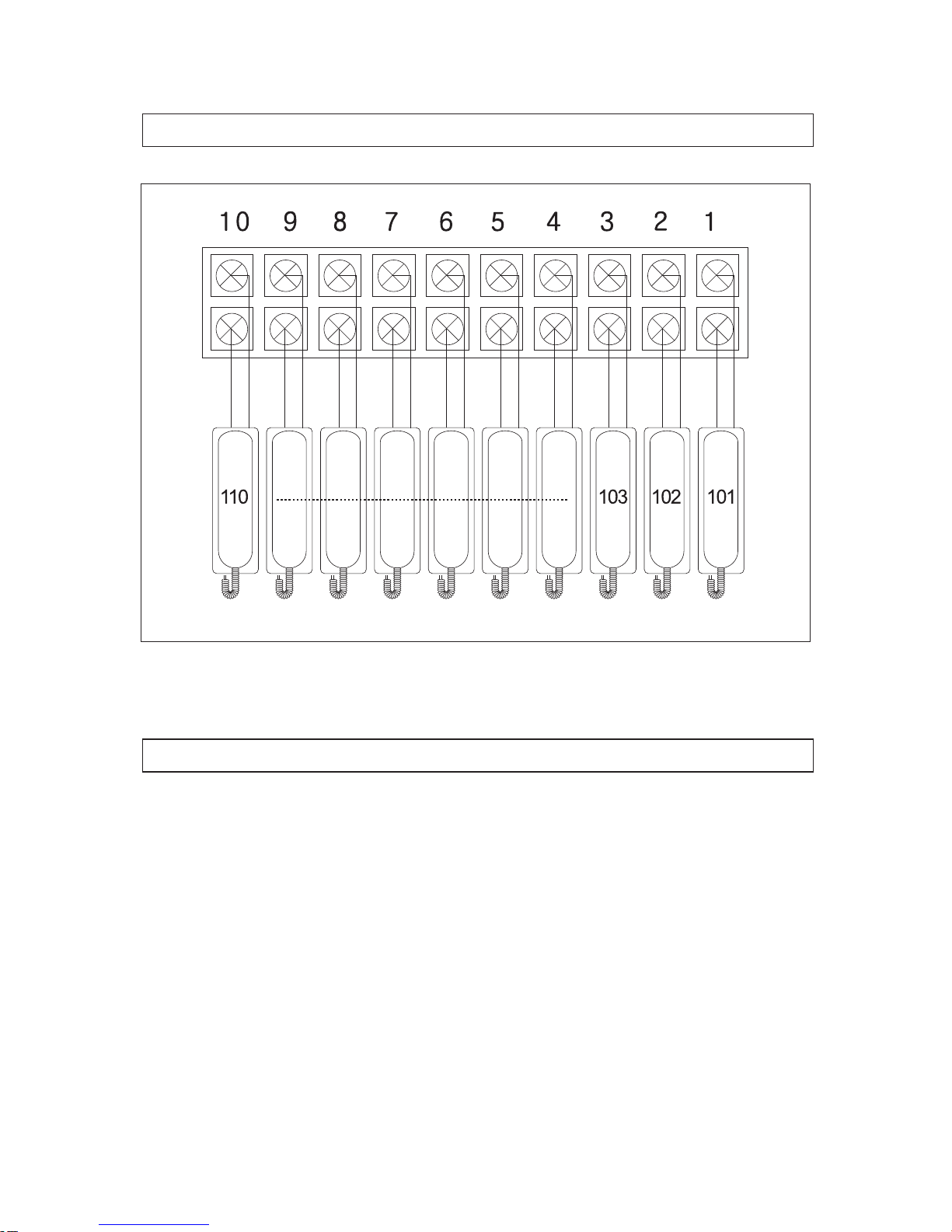
6. Wiring
7. Precautions
•Turn on the power switch of the product.
•When damage or defects are found in the product, immediately contact the
customer support team of the head office.
•Do not place flowerpot or water bottle on the product.
•Use circuit breakers suitable for internal wiring of the building (Both phases
have to be disconnected.). The circuit breakers should work immediately
when fire or other dangers are detected in the product.
•Perform installation or repairing of the product after power off.
•Pay attention not to let the call signal ring for a long time as it may adversely
affect the internal circuit of the interphone exchange.
Page 11

-11-
8. Others
9. Specifications and Features
1) Configuration
① CLS-10
② Expansion Units: CLS-10T(L)
CLS-10T(R)
CLS-10W
2) Specifications and Features
. Rated voltage: 200V~. 60Hz, DC24V 1A
. Used lines: Two lines a circuit
. Call distance: 2km (0.65 cable)
. Dimension (mm): 290(W) x 138(H) x 275(D)
■ Read this User’s Guide carefully before you report defects.
■ The following do not correspond to troubles. Check the product and contact
your local representative or the service team of the head office.
■ We will do our best for satisfactory service.
Page 12

-12-
MEMO
Page 13

-13-
MEMO
Page 14

513-11, Sangdaewon-dong, Jungwon-gu, Seongnam-si, Gyeonggi-do, Korea
Int’l Business Dept. Tel. : +82-31-7393-540~550 Fax. : +82-31-745-2133
Web site : www.commax.com
Printed In Korea / 2011.06.104
PM4010000010
 Loading...