

Page 1

REMOTE AUTO ALARM & REMOTE
STARTER SYSTEM
INSTALLATION MANUAL
This COMMANDO vehicle security is warranted to the original consumer
purchaser, to be free from defects in material and workmanship. The manufacturer
will repair or replace, at it's option, and free of charge during the first 12 months
of the warranty period, any part which prove defective in material or workmanship
under normal installation, use and service, provided the product is returned to our
factory, transportation charges prepaid. Products returned to our factory must be
accompanied by copy of purchase receipt. Warranty is limited to defective parts
and/or replacement parts only and excludes any incidental and consequential
damages connected therewith. The manufacturer, of this theft deterrent systems
makes no warranty against the theft of vehicle or its content. This warranty is not
to be construed as an insurance policy against loss.
After the first 12 months of the warranty period there will be a charge. ( required)
for repairing and/or replacing any defective parts.
WARRANTY ON INSTALLATION LABOR, REINSTALLATION AND REMOVAL CHARGES
ARE NOT THE RESPONSIBILITY OF THE MANUFACTURER.
OPTIONAL ACCESSORIES
Channel Expander
Glass Break Sensor
Interior Radar Sensor
Window Roll-Up Module
Trunk Release Solenoid
MADE IN USA
LIMITED WARRANTY
c 10-02
Vehicle Security
NOTE: ALL LCD 2 WAY REMOTE WARRANTY FOR 12 MONTHS
FROM DATE OF PURCHASE
FM-5005 COMBO
Alarm Features
One 5 Button Two Way LCD Display Withe Pager Remote
One 5 Button Code Hopping Remote Controls
Built-In Side-Light Relay Programmable (+/-)
Plug-in user programmable Coded Override Switch
Plug-in Dual-Zone Dual Adjust Piezo Sensor
Horn Output
Remote Door Locking/Unlocking with positive & negative outputs
Passenger Unlock Output
Two Auxiliary Channels with Selectable Output Types, ( Pulsed, Timed or Latched )
User-Selectable Auto-Arming
User-Selectable Auto-Rearming
Remote Panic with Smart Locking/Unlocking
User-Selectable AutoLock - Instant or RPM dependant
Remote Keyless Entry and Accessory Activation Even in Valet Mode
Remote-Controlled Courtesy Lighting
Pre-wired LED, Sensor, and Valet Switch Connectors
Auto Activation of Auxiliary 2 Output
Auto Disarm with Auxiliary 1 Activation (Trunk Release Output)
Smart Remote Trunk Release
Alarm Trigger Identification
Starter Features
True RPM Sensing for Real Time Cranking
RPM Learning Indication
Dual Mode reliable Smart Engine Run Sensing (Tackles Mode Only)
Gas or Diesel Mode with glow plug input
Cold Start Timer (Programmable)
Dedicated Starter Active Output for factory transponder bypass
Starter Disable Output for Anti Grind feature
Factory Disarm Output
Factory Rearm Output
Two Ignition Relay Outputs
Stop & Go Mode
Selectable Engine Run Time
COMMANDO
Page 2
SYSTEM CONTENTS
1
10
Each system contains the following components:
1- Brain Module
1- 5 Button Transmitter
1- One 5 Button Two Way LCD Display Withe Pager Remote
1- 6 Tone Siren
1- Impact Sensor Dual Zone W/ Harness
1- 20 pin wiring harness
1- (12 G.) Wire Harness W/2 Fuse Holders
1- 3 pin door lock harness
1- 4 pin wiring harness For Sensor
1- Red Status L.E.D.
1- Push Button Switch
1- Hood Pin Switch
Note: Read this instruction manual thoroughly. Important: This
unit is designed for a professional installation only. Any installation
performed by an unqualified installer, Will void the warranty.
INTRUSION ALERT
If a sensor input (door switch, shock sensor) has been violated while the system was armed,
upon disarming the alarm system, the siren will confirm with 3 disarming siren chirps and 3
light flashes indicating the alarm had been tripped. Turning the ignition to on position the
LED will flash 8 cycles indicating the trigger zone,
6 Hood/Trunk trigger
7 Reserved
8 Reserved
9 Reserved
10 +12 volt power interrupt error
LED Description
flashes
LED Description
flashes
AUTOMATIC FAULTY ZONE ELIMINATION
If while armed, a faulty zone is detected and the alarm is triggered, the siren will sound and the
lights will flash for 4 cycles of 45 seconds duration each. Total 4 minutes. After these 4
cycles, the alarm will automatically reset and bypass the defective zone. Upon disarming the
alarm system, 3 chirps and 3 light flashes will indicate that the alarm has been triggered.
SYSTEM DIAGNOSTIC
Sensor 2
Shock sensor
Optional sensor
Door trigger
Reserved
1
2
3
4
5
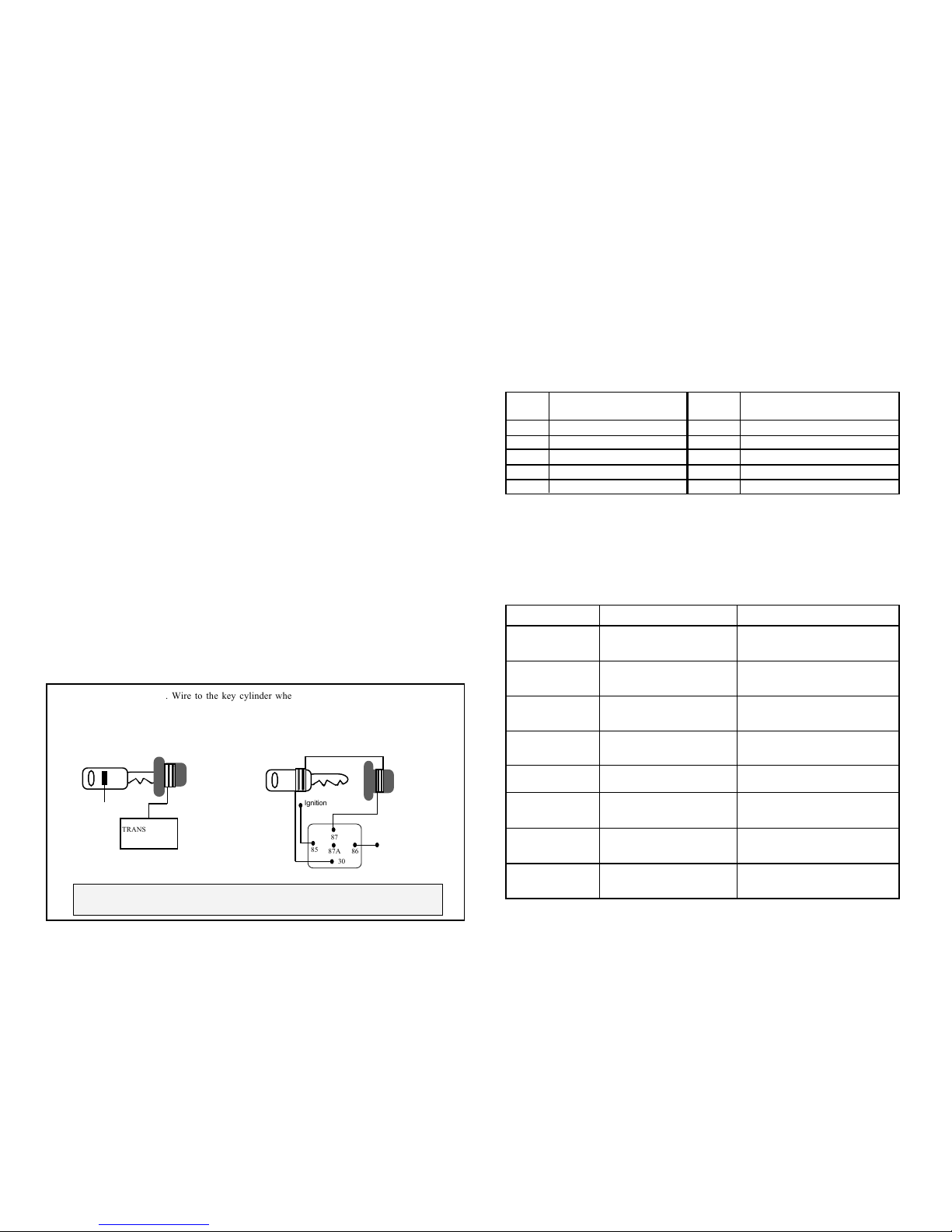
The GM PASSKEY 3 AND FORD P.A.T. Antitheft system works with a glass tube called a transponder
located in the ignition key that sends and receives data via a coil on the ignition switch. A module that
controls fuel distribution to the engine receives this information. If the module does not receive a
proper code or no code when starting, it will cut the fuel supply to the engine. Some manufacturers of
aftermarket security offer modules to bypass this security to allow you to add a remote starter. If you
do not have one of these modules available to you, can use the following method.
BPG-1 GM PASSKEY & VATS MODULE BPF-1 P.A.T.S. BYPASS MODULE
PASSKEY & P.A.T.S. BYPASS:(USE THE OPTIONAL)
PASSKEY & P.A.T.S. BYPASS
Ground out when
running (-)
Transponder
23
4
23
4
23
4
23
4
86
85
87
87A
30
Ignition
TRANSPONDER
MODULE
2
3
2
3
2
3
2
3
From pin 87 run a 22 (G). Wire to the key cylinder where you wrap the wire tightly 8 to 9
times around the cylinder, leave approx. 3 inches before wrapping it around one of the
vehicles keys then returning the end of the wire to pin 30. This will introduce the key into
the circuit only wen the remote starter is activated therefore maintaining the integrity of
the security
TROUBLE SHOOTING
Probable Cause
Problem
Unit will not operate
All power inputs are not connected
to 12V+
Remote start in Service mode
LED is ON solid
Turn ignition key to ON position, press
and hold service switch for 5 sec. LED
will go out
Ignition #1 (Yellow Wire)
is not getting power.
RS will not go into
Code Learning or
Programming Mode.
Connect the (Yellow) Wire to ignition.
See manual page 4 on COLD START.
Check Brake switch input (Green/White)
for (+) or Hood input (Wire/Black) for (-)
shorted to ground
Connect (Violet/White) wire to Factory
Alarm disarm wire.
Vehicle has a factory alarm sys..
Car Horn Honks and
Vehicle will not start.
RS in Automatic Cold
Start Activation Mode.
Vehicle starts without
pressing Remote
Transmitter.
Extend the (Black/gray) wire from the
main harness to a TACH wire.
Voltage sense is not working.
Use the TACH. sense.
Vehicle cranks and
begins to run, then
shuts off.
Vehicle has theft deterrent system
that prevents starting w/o key in
ignition.
See manual page 1 on Passlock PATS
theft deterrent systems.
Vehicle cranks and
begins to run, then
shuts off.
Keyless Entry operates
but engine will not start
Vehicle will not
remote start
Safety inputs are triggered
Main inputs heavy gauge red wires and
red fused wire on main harness must be
connected to 12+
Suggestions
Page 3

2
9
V
TRANSMITTER BUTTON OPERATION
IMPORTANT: The microprocessor alarm system has been designed so that upon arming,
Sensor 1 & 2 triggers will be delayed for 10 seconds. This is to give the electronics in the
vehicle, a chance to stabilize (Window roll-up, shock sensor, etc.).
ACTIVE ARMING MODE
Press transmitter button #1 momentarily to arm the alarm system. The alarm will arm and the
siren will chirp once, sidelights will blink, doors will lock automatically, optional starter disable
feature will be activated and the LED will turn on solid then begin flashing slowly after a 10
second delay.
DISARMING THE SYSTEM
Press transmitter button #2 momentarily to disarm the alarm system. The alarm will arm and
the siren will chirp twice, sidelights will flash twice LED will turn off Optional starter disable
feature will be deactivated Door locks will unlock automatically Dome light will be illuminated
for 30 seconds or until ignition key is turned to accessory “ON” position.
ARMING WITH TRANSMITTER (NO CHIRP)
Press transmitter button #5 momentarily. Then press button #1 the alarm will arm silently (no
siren chirps).
DISARMING WITH TRANSMITTER (NO CHIRP)
Press transmitter button #5 momentarily. Then press button #2 the alarm will disarm silently
(no siren chirps).
PASSIVE ARMING MODE
In passive arming mode, upon closing the last door there will be a 30 second arming delay. The
LED will be flashing rapidly and 5 seconds later parking light will flash two times indicating that
the system is in passive arming phase. After 30 seconds, the alarm will arm (Programmable).
ONE TIME PASSIVE ARMING DISABLE
Arm and disarm the alarm within 10 seconds, this will disable passive arming until you either
turn the ignition on, or arm the alarm and wait 10 seconds then disarm.
ARMING WITH DEFECTIVE ZONE ALERT
After arming the alarm (active or passive) .if a defective zone has been detected. The alarm will
confirm the detection of the defective zone by chirping the siren and flashing the lights 4
times. Also will identify the defective zone with LED. All defective zones will be bypassed until
they become good then the alarm will start monitoring them except both sensor once bypassed
they stay bypassed until you disarm and arm the unit.
PANIC MODE
For emergency situations, press and hold button #1, of the transmitter for 3 seconds. This will
activate the panic mode. The alarm siren will sound, armed output will be active, doors will
unlock and the parking lights will flash for 30 seconds (or until the transmitter button #2 is
pressed. (If ignition is on while panicking the doors will lock.
ALARM TRIGGERED
If a violation of the vehicle is taking place, the siren will sound, horn will flash, and the parking
lights will flash for 45 seconds. After this 45 seconds duration, the alarm will automatically
reset and resume protecting the vehicle. Sensor 1 sensor 2 triggers will sound the alarm 30
seconds.
PROGRAMMING THE UNIT
FEATURE PROGRAMMING MODE
1- Turn Ignition key ON
2- Within 10 seconds press VALET switch 5 times. The siren will chirp 3 times indicating you
are in feature programming mode.
3- Select the feature you want to change by pressing the valet switch the number of
times as the feature number. (Every time valet switch is pressed the siren will chirp once).
4- Select the desired option by pressing the transmitter’s buttons 1, 2 or 3.
Siren chirps will follow each button press, once for button 1, twice for button 2 and three
times for button 3.
PARKING LIGHT POLARITY SELECTION:
Remove the plastic cover of the control module and find jumpers W5 and W2 on the PCB.
Select Parking Light Polarity output by connecting the center tap to “+” or “-”of jumper W5.
Prog. Coded Override
Ignition Unlock - Off
Set Starter for Diesel
#1
#2
#3
#4
#5
#6
#7
#8
#9
#10
#11
#12
#13
#14
#15
#16
#17
#18
#19
#20
#21
#22
#23
#24
TX But. 1 Mode 1
TX But. 2 Mode 2
TX But. 3 Mode 3
PROGRAMMING TABLE
#s
Passive Arm Disable
Auto Rearm Disable
Chirps Enable
Ignition Lock Enable
Ignition Unlock All doors
Unlock Single Pulse
Lock/Unlock Pulse 1sec.
Lock on Passive Arm Disable
Door Trigger delay disable
Bad door zone report in 5 sec.
Activate Aux.2 upon arm-disable
Aux.1 pulsed
Aux. 2 pulsed
Disarm with Aux. 1 Disable
Starter in Valet Disable
Door lock Upon Starter
Door lock after Shutdown
Run Time 12 Min
Cold Start Every 2 hours
Smart Start Enable
Learn RPM threshold
Adding 2 way FM Module
Aux. Relay Out for Ignition-2
Aux 3- Horn Out
Passive Arm Enable
Auto Rearm Enable
Chirps Disable
Ignition Lock Disable
Ignition Unlock – Driver door
Unlock Double Pulse
Lock/Unlock Pulse 3sec
Lock on Passive Arm Enable
Door trigger delay Enable
Disable bad door zone report
Activate Aux.2 upon arm-Enable
Aux.1 Timed
Aux. 2 Timed
Disarm with Aux. 1 Enable
Starter in Valet Enable
No Door lock Upon Starter
No Door lock after Shutdown
Run Time 24 Min
Cold Start Every 1 hour
RPM Start Enable
Set starter for Gasoline Vehicle
Program 2-way FM remote
Aux. Relay Out for Accessory-2
Aux 3- Ignition Out
Aux. 1 Latched
Aux. 2 Latched
Aux. Relay Out for
Starter-2
RESET TO FACTORY DEFAULT SETTING:
ENTER PROGRAM MODE (SEE ABOVE)
PRESS AND HOLD CHANNEL 3 (OR BUTTON #3 ) FOR 5 SECONDS LIGHT WILL FLASH 3
TIMES .AND ALL PROGRAMMABLE FEATURES WILL GO BACK TO FACTORY DEFAULT
SETTINGS. ( WHICH IS ALL MODE 1 )
Column 1 - Factory Default
t
Page 4
8
3
ALARM SPECIAL FEATURES
WARN-AWAY
Dual zone shock sensor, zone one when triggered activates causes the alarm to chirp five times
indicating a Warn-away condition, second zone when active, triggers the Alarm.
VALET MODE
Valet mode entry. Disarm the alarm, turn the Ignition ON, and hold the push button valet switch
for 5 seconds until LED turns ON and parking light flash once. Door lock/ unlock, and all aux
outputs respond to transmitter activation (Keyless Entry).
Valet mode ext. Turn the Ignition ON; hold the push button valet switch for 5 seconds until
LED turns OFF and parking light flash twice.
EMERGENCY OVERRIDE
Disarm the alarm without transmitters. Turn Ignition ON, hold the push button switch down for
5 seconds, the siren will turn off and alarm will disarm.
If emergency coded override is programmed then turn ignition on, press the push button switch
the number of times that correspond to the pre programmed code, hold the push button switch
down for 5 seconds, the siren will turn off and alarm will disarm.
SENSOR DISABLE FEATURE
Disable the sensors for a single arm cycle, by pressing the 1st button to Arm and within 10
seconds pressing the 1st button again. The siren and parking light will flash five times,
that will eliminate sensor for that arm cycle. Rearming the alarm will re-enable the sensor.
ACCIDENTAL DISARM (AUTO REARMING)
If the alarm has been armed for at least 10 seconds and has been disarmed with the transmitter
by mistake. It will automatically rearm itself within 30 seconds. Opening the door or turning on
the ignition key will cancel rearming. This feature will be always active no matter if the alarm
is in active or passive mode.
To disable this feature, go to programming mode and turn this feature to OFF.
DOOR TRIGGER DELAY IN PASSIVE MODE
If enabled, when the alarm arm’s passively, upon opening the door siren will chirp for 10 seconds
then will trigger the alarm, unless you turn the ignition on within that 10 seconds. This will disarm
the system. This enables you to use the alarm without remote
SECURE AUXILIARY OUTPUTS
Each auxiliary output can be programmed so that it can be activated only when the system is
disarmed and the ignition switch is off.
This feature is particularly useful when the output is used for trunk release purpose. This prevents
the trunk to be released accidentally by pressing the trunk release button.
PERRSONALIZED OVERRIDE CODE
To select you personal security code to override the alarm. Go to access feature programming
mode location # 4, press button # 3 on the transmitter, select your personal security code by
pressing the valet switch to a desired number (1 to 15), then turn the ignition off.To disarm the
alarm when triggered, turn ignition on press the valet switch to the selected number times and
hold for 10 seconds on the last press until the alarm turns off.
PROGRAMING TRANSMITTERS
Turn the ignition key 3 times on/off; leave the ignition key in ON position, within 3 seconds
siren will chirp 3 times.
Press valet switch for 5 seconds the siren will chirp 5 times and LED comes on solid, then press
button # 1 on the remote transmitter one time. The siren will chirp once, press button #1 one
more time the siren will chirp twice this will confirm that the alarm has learned that
transmitter. If you want to teach another transmitter with a different code press button # 1 one
time on the second transmitter the siren will chirp once. Then press button #1 one more time
on the transmitter siren will chirp twice you can teach 4 different codes.
TRANSMITTER TEACHING FOR SECOND CAR OPERATION
Same as programming transmitter, but press the 5 the or function button 2 times then press button
# 1, siren will chirp once then repeat procedure one more time, siren will chirp twice indicating it
learned the transmitter
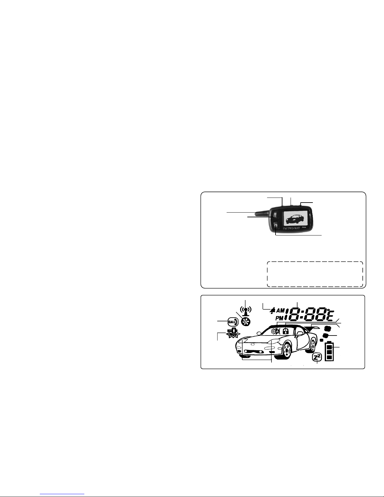
TWO WAY FM REMOTE OPERATION
Button #1
Door Lock / Unlock
Arm & Disarm
Press AND Hold for PANIC
Button #3
TRUNK OPEN
Button #2
REMOTE ENGINE
START
Antenna
LCD Display
Press Button 2 & 3 And Hold for
program CLOCK Then Button # 2 hour, Button # 3
mints. When set time press Button #1 to EXIT.
Repeat same Programming for
Alarm Clock and Start Clock
Button #1 = Arm & Disarm
Button #2 = Remote Engine Start
Button #3 = Trunk Open
Button #4 = 3rd Channel ( programmable)
Button #5 = Backlight & (Programming)
Button #2&3 = (PROGRAM) CLOCK/ALARM CLOCK/START CLOCK
Button #4 --3rd CHANNEL
*
Button #5 Backlight &
Programming
STATUS,CHIRP ENABLE &
DISABLE
REMOTE SOUND ENABLE
& DISABLE
LOCATION
1 - CLOCK
2 - ALARM CLOCK
3 - AUTO START CLOCK
TWO WAY FM PAGER PROGRAMMING
Installing the Two Way FM Pager requires teaching the Alarm system the FM pager interface
module ID code. It is accomplished in step 22 of the programming table.
Connect the interface module to the Alarm system, enter step 22 in the programming table,
press button #1, of the one-way transmitter.
Additional FM transmitter is also programmed in step 22 of the programming table.
The procedure is:
Enter step 22 in the programming table, press button #2, of the two-way transmitter.
DRIVER CALLING:
When alarm is in disarm mode, press VALET Push Button switch momentarily will Page the
remote with 4 Beeps to indicate a calling function from the Vehicle.
Lock/Unlock
Trunk release
Engine running
Valet mode
Parking lights
Shock sensor trigger
Driver
calling
Engine starting
Antenna tranmitting
Alarm clock mode
Clock hour,minute indication
Accessorie Currently Available: • • • • • Channel Expander • • • • •
battery status
Siren alert
Page 5
7
REMOTE START FEATURES
TRANSMITTER FUNCTIONS
4
ENGINE RPM PROGRAMMING
Select Engine Start RPM detection - step 20 in the programming table.
With engine running select step 21 in the programming table, note that the LED is
blinking, indicating that the RPM signal is detected properly, press button 1 on your
remote control to record the idle RPM.
ENGINE RUN DETECTION
There are two modes of engine run detection
RPM – Engine run sensing is accomplished by supplying an RPM signal to the unit and
teaching the “vehicle engine idle RPM”. Engine stalled condition is defined as zero
engine RPM.
Smart Sense – Engine run is determined by measuring the battery voltage and engine noise.
Engine stalled condition is defined if both the battery voltage and engine noise have been
fallen bellow a per-determined threshold.
ENGINE START DETECTION
Engine start is detected only when using the RPM mode, in this mode RPM timing is compared
to pre programmed idle RPM, engine start is defined as 50% of idle RPM. If engine RPM did
not reach that level within 10 seconds, engine cranking will be terminated.
If Smart Sense is selected engine start is controlled by timing only.
DIESEL/GASOLINE MODE
Gasoline mode - Ignition is turned On 5 seconds before start.
Diesel Mode - Ignition is turned On 10 seconds before start or until the Glow plug is turned
Off whichever comes first.
COLD START
Cold Start is programmable to every 2 or 1 hour intervals.
Enable Cold Start – with Ignition Off simultaneously press the brake pedal Valet switch and
button 1 on your remote - Parking lights will flash twice confirming that the feature has been
enabled.
* This feature will be canceled if the alarm has been armed and disarmed or
ignition has been turned On.
STOP & GO MODE
With engine running press remote start button on your transmitter, sidelights will flash twice
indicating STOP & GO mode enabled, turn off the Ignition switch, the engine will continue
running.
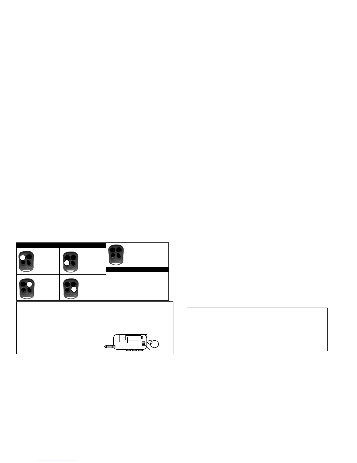
TRANSMITTER FUNCTIONS WITH DEFAULT SETTINGS
Button # 1 upper left button (arm with chirps and press 3 seconds for panic)
Button # 2 upper right button (disarm with chirps and press one more time for passenger unlock)
Button # 3 lower left button (press for 2 seconds for trunk release, aux 1)
Button # 4 lower right button (press for remote start)
Button # 5 Side right button (function button)
Transmitter functions with function button pressed once (with default settings)
Button # 1 upper left button (arm without chirps)
Button # 2 upper right button (disarm without chirps and press one more time for passenger unlock)
Button # 3 lower left button (press for aux 2)
Button # 4 lower right button (not used)
Transmitter functions with function button pressed two times (with default settings)
Button # 1 upper left button (arm with chirps, second car operation)
Button # 2 upper right button (disarm with chirps and press one more time for passenger unlock,
second car operation)
Button # 3 lower left button (trunk release, second car operation)
Button # 4 lower right button (remote start, second car operation)
Transmitter functions with function button pressed three times (with default settings)
Button # 1 upper left button (not used)
Button # 2 upper right button (not used)
Button # 3 lower left button (sensor adjust & test mode)
Button # 4 lower right button (not used)
BUTTON #1
LOCK
ARM
BUTTON #2
UNLOCK
DISARM
BUTTON #3
Hold 3 Sec.
For TRUNK
BUTTON #4
REMOTE
START
BUTTON #5 (function)
E
Press Momentary Will
Shift to Next Bank.
Remote Operation In Bank #1
#5 +1= Silent Arm
#5 +2= Silent Disarm
#5 +3= 4 Th. Channel
#5 +4= Shock sensor disable
3
4
1
2
Remote Operation In Bank #2
LOW BATTERY INDICATOR :
The Pager will indicate when it is time to replace the battery by lighting the
BATTERY symbol. This indication is not for the pager. But rater the remote transmitter. Audible
paging "beeps" will become none audible before battery replacement is necessary for the remote
transmitter.
REPLACING THE BATTERY :
Remove battery cover. And Remove old battery.
Replace with 1.5V AAA Battery
Two Way Remote
2
4
1
3
Notes
+
BATTERY
Back of the Remote
cover lock
Page 6
REMOTE ALARM & STARTER WIRING
65
NOTE
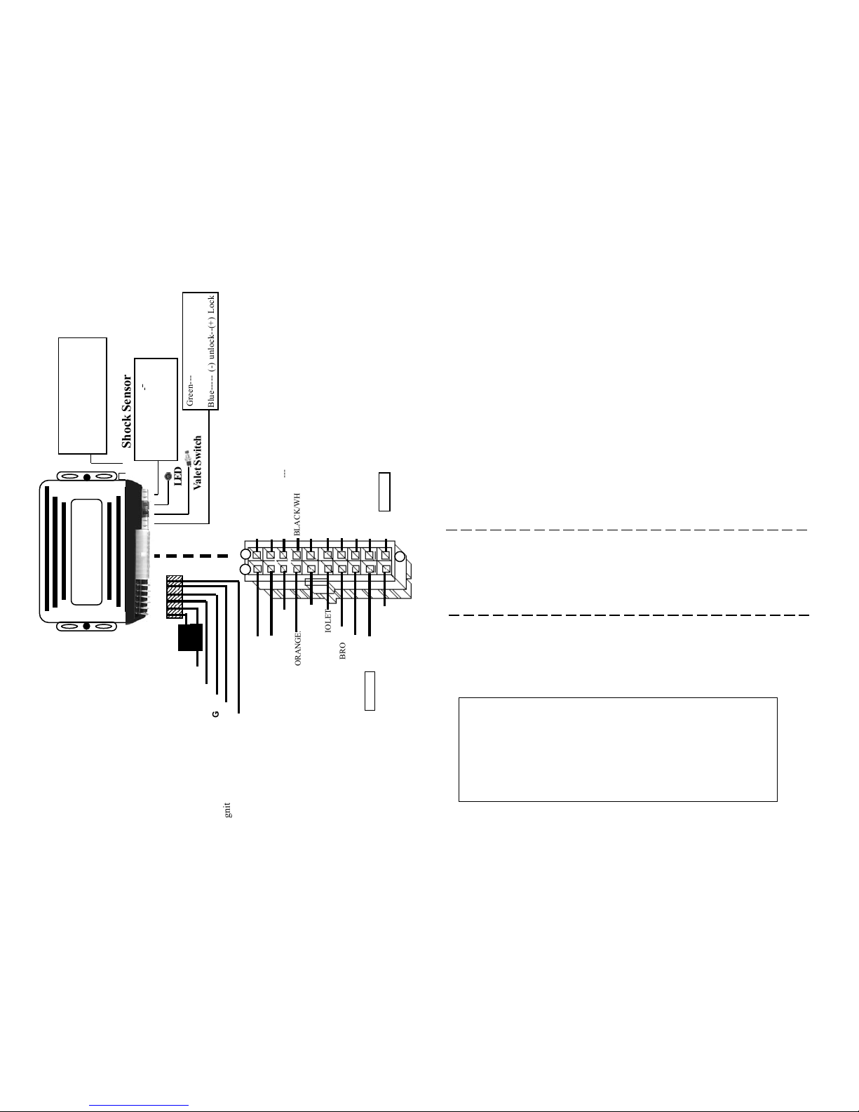
1-GREEN/WHITE:---2-BLACK/GRAY----3-RED/WHITE:------4-BLACK/WHITE:--5-YELLOW:--------6-BLUE/YELLOW:-7-BLUE/WHITE:----8-BLUE/ORANGE:--9-BLACK:----------10-RED:-------------11-VIOLET:---------12-GREEN:----------13-WHITE/BLACK:14-ORANGE:-------15-VIOLET/WHITE:
16-WHITE/VIOLET:17-BROWN:--------18-GRAY: -----------19-WHITE:----------20-BROWN/WHITE:-
Connect to the Brake light switch (+) when Brake is pressed.
RPM Input Wire Tachometer.
Aux 2 Output (-) (Trunk)
Dome Light Output (-)
Connect to Ignition switch wire which is powered by 12V.+ even on cranking.
Glow plug Input (+)
Passenger Unlock Output (-)
Ground Output when Running
Connect to a Good Ground.
Connect to Battery constant 12V.+ power
( WITH FUSE HOLDER)
Door pin (+) Trigger.
Door pin (-) Trigger.
Hood or Trunk Input (-) Trigger.
Connect to a 30 Amp. Relay for Starter Disable Output (-)
Factory Alarm Disarm (-)
Factory Alarm Arm (-)
Connect to the red wire of Siren (+) Output.
Aux 1 Output (-)
Connect to the (+) side of parking lights
( WITH FUSE HOLDER )
Aux 3 Output (-)
RED: -----------RED: -----------BROWN:-------ORANGE:------YELLOW:------VIOLET: --------
Connect to Battery constant 12V. (+) ( POWER WITH FUSE HOLDER )
Connect to Battery constant 12V. (+) ( POWER WITH FUSE HOLDER)
Connect to Ignition switch #2 (Aux Relay if needed).
Connect to Ignition switch ACC. Circuit (Air Cond./Heater).
Connect to Ignition switch wire which is powered by 12V.+ even on cranking.
Connect to Starter wire witch is powered ONLY on cranking position.
4- PIN WHITE CONNECTOR:--------3- PIN WHITE CONNECTOR:--------2- PIN RED CONNECTOR:-----------2- PIN BLUE CONNECTOR:----------
3- PIN WHITE SIDE CONNECTOR:---
Plug in Shock Sensor.
Plug in Door Lock Unlock Wire.
Plug in LED and mount in a desirable location.
Plug in PROGRAM/VALET Switch.
Plug in TWO WAY FM MODULE.
COMMANDO
FM-5005 COMBO
12345
1
234
5
1
234
5
1
234
5
1
234
5
1
234
5
1
234
5
1
234
5
1
234
5
1
234
5
1
234
5
1
234
5
12345
Shock Sensor
LED
Valet Switch
Blue----- (-) unlock--(+) Lock
Green--- (-) lock--(+) Unlock
Red---(+) 12v.out
t
t
RED: --
Battery 12V. (+)--
Battery 12V. (+)--
RED: ---------
BROWN:----
ORANGE:---
YELLOW:---
Ignition #2-----
ACC circuit---
Ignition #1 12V.+ --
Starter wire--
VIOLET: ----
Side Lights (+)----------------
1
20
GREEN/WHITE:----
BLACK/GRAY-------
WHITE/RED:--------
BLACK/WHITE:----
YELLOW:------------
BLUE/YELLOW:---
BLUE/WHITE:------
BLUE/ORANGE:---
BLACK:--------------
RED:------------------
VIOLET:
GREEN:
WHITE/BLACK:
VIOLET/WHITE:-----
WHITE/VIOLET
ORANGE:
BROWN:
GRay:
WHITE:
BROWN/WHITE:
11
10
Fuse 20amp
Brake light switch (+)
RPM Input Wire Tachometer.
Aux 2 Output (-) (Trunk)
Dome Light Output (-)
Ignition switch power 12V.+
Glow plug Input (+)
Passenger Unlock Output (-)
Ground Output when Runing
Battery Ground
Battery 12V.+ power
Aux 3 Output (-)------------
Door pin (+) Trigger-------
Door pin (-) Trigger--------
Hood Input (-) Trigger----
Starter Disable Output (-)-
Factory Alarm Disarm (-)--
Factory Alarm Arm (-) ----
Siren Output (+)- ------------
Aux 1 Output (-) ---------------
White----Warn-away
Blue-----Sensor Trigger
Red-----+12v.
Black----Ground
AUTOMATIC TRANSMISSION ONLY
DO NOT INSTALL ON MANUAL TRANSMISSION
"" Manufacturer is not responsible for any injury or damage
to cars with manual transmission ""
FUSES
Fuse 15amp
FM MODULE PLUG
Network Cable To Upgrade
For Two-Way FM Pager
System ( Optional )
 Loading...