

Page 1
VLP-M-KIT
INSTALLATION INSTRUCTIONS
The Command Access VLP-M-KIT is a eld-installable motorized latch-pullback baserail kit for the Von
Duprin 33/35 & 98/99 series devices.
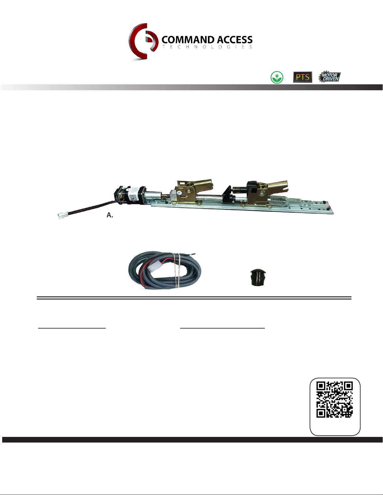
A.
Kit Includes
A.
1 - VLP-M-KIT Baserail Kit
B.
1 - 6’ Lead
C.
1 - Dogging Hole Cap
U.S. Customer Support
1-888-622-2377
B.
C.
Tools Required
• Cordless Drill
• 5/16 Nut driver (recommended) or Flat head
screwdriver
• #2 Phillips head screwdriver
Visit our website for more details
www.CommandAccess.com
Additional
Information
1
Canada Customer Support
1-855-823-3002
02/16 Doc # 20272_E
Page 2

Technical Information
Specications
• Input Voltage: 24VDC +/- 10%
• Average Latch Retracon Current: 1 Amp
• Average Holding Current: 170 mA
PTS Video
Click or Scan
• Wire gauge: Minimum 20 gauge
Setting PtS
**Important Info**
Make sure to set PTS before nishing installaon!
Step 1-Press the device push pad to the desired seng. (this can be fully
depressed or less than fully depressed).
Step 2- While depressing the push pad, apply power. (i.e. presenng the
credenal to the reader).
Step 3- Connue to keep pad depressed, the device will beep 6 mes. Aer the
MM4 Switches
beeps have stopped, release the pad and now the adjustment is complete.
If not to your liking repeat the three steps. That’s all there is to it.
trouBleShooting & DiagnoSticS
BeePS exPlanation Solution
2 Beeps
3 Beeps
4 Beeps
5 Beeps
6 Beeps
7 Beeps
Over Voltage
Under Voltage
Failed Sensor
Forced Release
Push pad is depressed. Device is
re-adjusng
Over-travel or mechanical
obstrucon
> 28V unit will shut down. Check voltage & adjust to 24 V.
< 22V unit will shut down. Check voltage & adjust to 24 V.
Verify all 3 sensor wires are installed correctly. Replace sensor if
problem persists by contacng CAT tech support.
Device will automacally re-engage within 5 seconds.
Check to make sure the push pad is not stuck or catching on
anything.
If mechanical obstrucon, remove & push pad down unl
beeping stops to reset. If no obstrucon, the pad may have
been pushed in too far during PTS calibraon. Recalibrate
with the pad slightly out. If problem persists, verify the
magnet is within 1/4” of the sensor at the end of travel.
2
U.S. Customer Support
1-888-622-2377
Visit our website for more details
www.CommandAccess.com
Canada Customer Support
1-855-823-3002
Page 3

• Remove head cover.
3
• Remove mounting bracket.
4
1
Head cover
2
• Remove (2) screws attaching bracket
to baserail with 5/16 nut driver or
at head screw driver.
Screws
Bracket
• Remove case for device.
Case
• Remove push pad by pulling pad
guides up then moving push pad
forward & then upward.
Push pad
• Detach the head assembly form the
base rail by removing both screws on
the backside of the baserail.
Screws
3
Page 4

• Remove the “C” clip and pin attaching
the latch to the baserail.
• Swap your mechanical baserail for the
electried baserail.
• Re-install the pin into the rst hole
• Re-install both screws attaching the
new baserail back to head assembly.
• Re-install “C” clip attaching the latch
to the new baserail.
• Next plug in MM4 module to power &
test motor functions before nishing
reassembly.
Screws
4
Page 5

• Replace push pad by placing over
activating arms & pushing down then
back towards end of device.
Push pad
• Slide baseplate back into case being
careful of motor wires.
Case
• Replace bracket & attach (2) screws with 5/16
nut drive or at head screw driver.
Bracket
Screws
• Replace head cover & (4) head
cover screws if present.
3
4
1
Head cover
2
• Replace mounting bracket.
Bracket
• Depress push pad & set PTS adjustment.
Setting PtS
Step 1-Press the device push pad to the desired seng. (this can be fully
depressed or less than fully depressed).
Step 2- While depressing the push pad, apply power. (i.e. presenng the
credenal to the reader).
Step 3- Connue to keep pad depressed, the device will beep 6 mes. Aer the
beeps have stopped, release the pad and now the adjustment is complete.
If not to your liking repeat the three steps. That’s all there is to it.
5
 Loading...