

Page 1
Installation Instructions
Bridge
Rectifier
Bridge
Rectifier
Mortise
Lock
Pocket
Mortise
Lock
Pocket
Mortise
Lock
Pocket
3/8 Wire Raceway
ETH Hinge Pocket
Bridge
Rectifier
Bridge
Rectifier
Plug
Mortise
Lock
Pocket
Mortise
Lock
Pocket
Mortise
Lock
Pocket
3/8 Wire Raceway
ETH Hinge Pocket
Bridge
Rectifier
Wire Transfer Hinge
Bridge
Rectifier
Plug
3/8 Wire Raceway
Mortise
Lock
Pocket
Mortise
Lock
Pocket
Mortise
Lock
Pocket
Bridge
Rectifier
Mortise
Lock
Pocket
ML35D & ML35W
Best Lock modied by Command Access Technologies
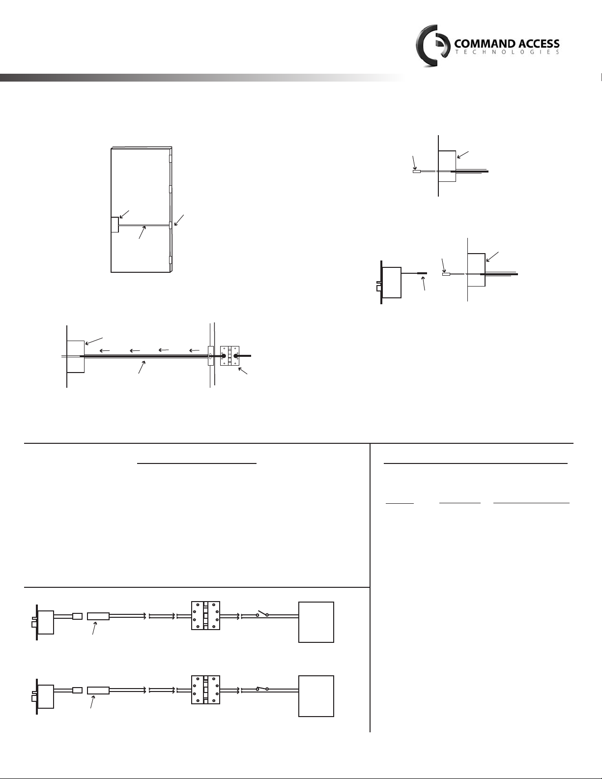
STEP 1: The door must be machined with a 3/8” wire raceway,
mortise lock pocket & prepped for a energy transfer
hinge. Make sure the mortise pocket is free of debris.
Mortise
Lock
Pocket
3/8 Wire Raceway
: Run the wires from the ETH hinge through the 3/8”
STEP 2
raceway starting at the ETH hinge & exiting into the
mortise pocket.
STEP 3
: Screw the ETH hinge to the door. At this time DO NOT
Mortise
Lock
Pocket
3/8 Wire Raceway
ETH Hinge Pocket
Wire Transfer Hinge
connect the hinge wires on the jamb side to the wires
coming from the power supply.
STEP 4: Connect the wires exiting the mortise pocket to the
Bridge Rectier (included).
Mortise
Lock
Bridge
Rectifier
STEP 5
: Connect the Bridge Rectier to the plug exiting the
Pocket
mortise chassis.
Mortise
Lock
Pocket
Bridge
Rectifier
Plug
: Carefully slip the connected mortise lock chassis into the
STEP 6
mortise pocket paying close attention not to pinch any
wires.
: Mount the chassis per manufacturer’s instructions.
STEP 7
: Connect the wires from the power supply at the ETH
STEP 8
hinge on the jamb side. Connect the hinge to the jamb.
LEGEND OF TERMS
EU
: (Fail Secure) When power is applied, the outside trim will unlock. When
power is removed, the outside trim is locked.
: (Fail Safe) When power is applied, the outside trim will lock. When
EL
power is removed, the outside trim is unlocked.
REX
: (Request to Exit Switch) Monitors the inside handle.
or
Power
Supply
or
Power
Supply
DPS*: (Door Position Switch) Monitors the door via the anti pick (Deadlatch).
LBM*: (Latchbolt Monitor Switch) Monitors the position of latchbolt.
* Not Available in all locks
Bridge Rectifier
Bridge Rectifier
Energy Transfer Hinge
Energy Transfer Hinge
Switch
EU (Fail Secure)
Switch
EL (Fail Safe)
12VAC/DC
24VAC/DC
12VAC/DC
24VAC/DC
EU (Fail Secure)
EL (Fail Safe)
Command Access Technologies | 22901 La Palma Ave. Yorba Linda, CA 92831 | Phone: (888) 622-2377 | www.CommandAccess.com
Command Access Technologies is not a licencee, aliated, associated or connected with Best or any of their subsidiaries or aliates.
ELECTRICAL SPECIFICATIONS
SOLENOIDS:
VOLTS
24VAC/DC
12VAC/DC
CURRENT
350mA
700mA
SWITCHES: 5A 124VAC/DC
: Green - Common (C)
REX
Blue - Normally Open (NO)
Gray - Normally Closed (NC)
LBM
: Green/Black - Common (C)
: Green/Red - Common (C)
DPS
Blue/Black - Normally Open (NO)
Gray/Black - Normally Closed (NC)
Blue/Red - Normally Open (NO)
Gray/Red - Normally Closed (NC)
COIL RESISTANCE
69 Ohms +/- 10%
18 Ohms +/- 10%
Page 2

Handing Instructions for ML35D & ML35W Mortise Locks
Not Field Handable
Template for ML35D & ML35W Mortise Locks
Please refer to the manufacturers original template
 Loading...