

CYLP-UL-M-KIT
INSTALLATION INSTRUCTIONS
The Command Access CYLP-UL-M-KIT is a eld-installable motorized latch-pullback kit for the Corbin
4000/5000 and Yale 7000 series exit devices
B.
A.
C.
D.
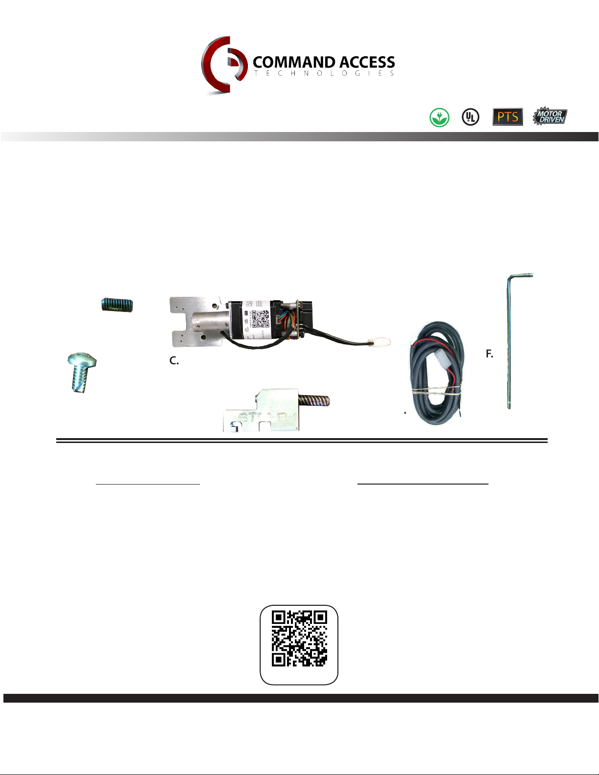
Kit Includes
A. 2 - Phillips screws
B. 2 - Hex screws
C. 1 - Motor Mount w/ MM4 series module
D. 1 - Acme Link Assembly
E. 1 - 6’ lead
F. 1 - 1/16” Hex Wrench
Installation Video
F.
E.
Tools Required
• Phillips screw driver
U.S. Customer Support
1-888-622-2377
Scan or Click
Visit our website for more details
www.CommandAccess.com
1
Canada Customer Support
1-855-823-3002
Doc # 20092_C

TECHNICAL INFORMATION
Speci f i c ationS
PTS Video
Click or Scan
Step 1-
Step 2-
Step 3-
• Input Voltage: 24VDC +/- 10%
MM4 Switches
• Average Latch Retracon Current: 1 Amp
• Average Holding Current: 170 mA
• Wire gauge: Minimum 18 gauge
High Torque Mode
• Average Latch Retracon Current: 2 Amp
• Average Holding Current: 250 mA
Setting PtS
**Important Info**
Make sure to set PTS before nishing installaon!
Press the device push pad to the desired seng. (this can be fully depressed
or less than fully depressed).
While depressing the push pad, apply power. (i.e. presenng the credenal
to the reader).
Connue to keep pad depressed, the device will beep 6 mes, roughly 5
seconds. Aer the beeps have stopped, release the pad and now the adjustment
is complete. If not to your liking repeat the three steps. That’s all there is to it.
trouBleShooting & DiagnoSticS
BeePS exPlanation Solution
2 Beeps
3 Beeps
4 Beeps
5 Beeps
6 Beeps
7 Beeps
U.S. Customer Support
Over Voltage
Under Voltage
Failed Sensor
Forced Release
Push pad is depressed. Device is
re-adjusng
Over-travel or mechanical
obstrucon
1-888-622-2377
Visit our website for more details
www.CommandAccess.com
> 28V unit will shut down. Check voltage & adjust to 24 V.
< 22V unit will shut down. Check voltage & adjust to 24 V.
Verify all 3 sensor wires are installed correctly. Replace sensor if
problem persists by contacng CAT tech support.
Device will automacally re-engage within 5 seconds.
Check to make sure the push pad is not stuck or catching on
anything.
If mechanical obstrucon, remove & push pad down unl
beeping stops to reset. If no obstrucon, the pad may have
been pushed in too far during PTS calibraon. Recalibrate
with the pad slightly out. If problem persists, verify the
magnet is within 1/4” of the sensor at the end of travel.
2
Canada Customer Support
1-855-823-3002

STEP 1 - Disassemble Exit Device
A. Remove End Cap & Filler Plate
B. If dogging is present remove by taking out 2 screws
1
STEP 2 - Installing Kit
A. Attach Acme link assembly to back of the activating bracket.
Activating bracket
2
3

Refer to this picture for next 2 steps
12
B. Using Hex wrench supplied tighten hex screw #1 to secure assembly to the device.
C. Using 1/16” Hex wrench supplied tighten hex screw #2 to lift assembly block until it’s level.
Acme Thread
D. Slide motor mount into the device. While sliding into position, feed acme screw into cylindrical housing.
Cylindrical housing
4

F. Attach Phillips screws provided to secure motor mount to device
E. Attach 6’ lead to MM3
E. Slide the ller plate back onto the device
Setting PtS
Step 1-Press the device push pad to the desired seng. (this can be fully
depressed or less than fully depressed).
Step 2- While depressing the push pad, apply power. (i.e. presenng the
credenal to the reader).
Step 3- Connue to keep pad depressed, the device will beep 6 mes. Aer the
beeps have stopped, release the pad and now the adjustment is complete.
If not to your liking repeat the three steps. That’s all there is to it.
5
 Loading...