

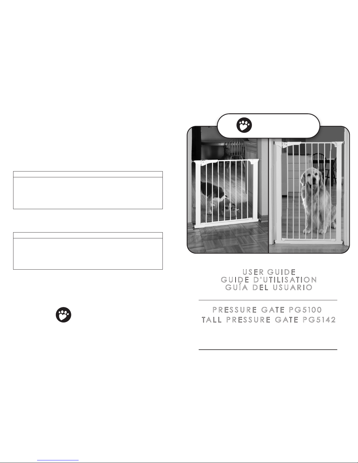
Fits openings 29” – 32” • Optional extension kit available
Pour des ouvertures de 73,5 à 81,5 cm • Rallonge disponible en option
Para aberturas de 29” a 32" • Hay disponible extensione opcionales
USER GUIDE
GUIDE D'UTILISATION
GUÍA DEL USUARIO
a division of KidCo
®
1013 Technology Way, Libertyville, IL 60048
800.553.5529
www.commandpet.com
Extension Placement Guide/Guía de colocación de las extensiones
PG6100 and PG6142 Extension Guide for Pressure Gate Model PG5100 and PG5142
Note: Each PG6100/PG6142 kit contains two extensions
Guide de positionnement des rallonges
Guides de rallonge PG6100 et PG6142 pour modèles
PG5100 et PG5142
Remarque : Chaque ensemble PG6100/PG6142 contient deux rallonges
Width Opening Extensions What You Need Placement
29”– 32” Basic Gate No extensions
32” – 34 ½” 1-PG6100/PG6142 Gate + 1 extension -1 on one end
34 ½” – 37” Gate + 2 extensions -1 on each end
37” – 40” 2-PG6100/PG6142 Gate + 3 extensions -2 on one end; 1 on other end
40” – 42 ½” Gate + 4 extensions -3 on one end; 1 on other end
42 ½” – 45” 3-PG6100/PG6142 Gate + 5 extensions -3 on one end; 2 on other end
45” – 47 ½” Gate + 6 extensions -3 on each end
Largeur d'ouverture Rallonges Matériel requis Positionnement
73,5 à 81.5 cm Barrière de base Sans rallonges
81.5 à 87,6 cm 1-PG6100/PG6142 Barrière + 1 rallonge -1 à une extrémité
87,6 à 93,9 cm Barrière + 2 rallonges -1 à chaque eextrémité
93,9 à 101,6 cm 2-PG6100/PG6142 Barrière + 3 rallonges -2 à une extrémité; 1 à l'autre extrémité
101,6 à 107,9 cm Barrière + 4 rallonges -3 à une extrémité; 1 à l’autre extrémité
107,9 à 114,3 cm 3-PG6100/PG6142 Barrière + 5 rallonges -3 à une extrémité; 2 à l'autre extrémité
114,3 à 120,6 cm Barrière + 6 rallonges -3 à chaque extrémité
c mmand
pet products
TM
PRESSURE GATE P G 5100
TALL PRESSURE GATE P G 5142
c mmand
pet products
TM
USER GUIDE • PG5100 PRESSURE GATE • PG5142 TALL PRESSURE GATE
2 23
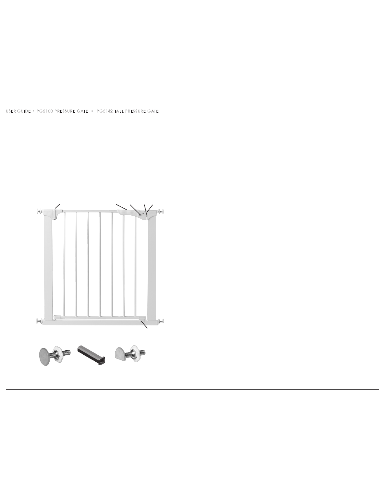
A Top Spindle (2)
B Spindle Housing (4)
C Bottom Spindle (2)
D Pressure Hinge
E Button (2)
F Pressure Plate
G Handle
H Hinge
I Locator
Parts list
PÁGINA DEJADA EN BLANCO INTENCIONADAMENTE
A
C
B
GH
I
EDF
USER GUIDE • PG5100 PRESSURE GATE • PG5142 TALL PRESSURE GATE
4
21
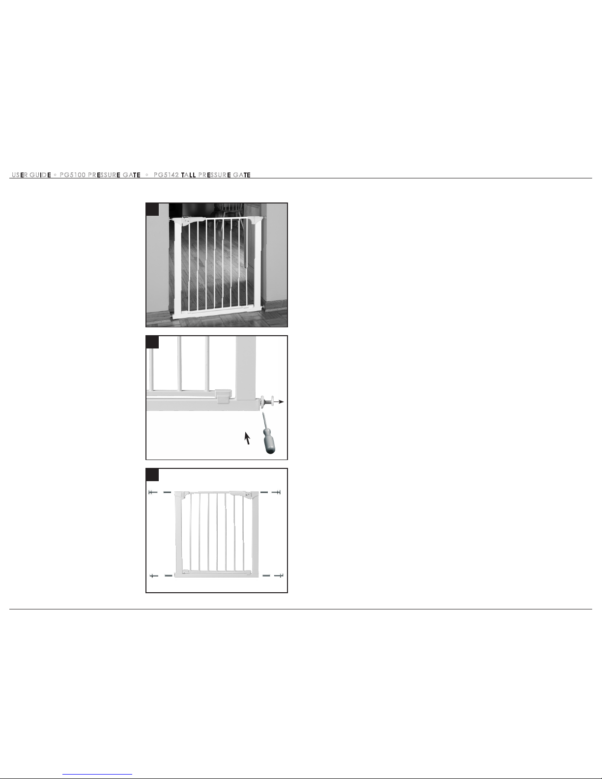
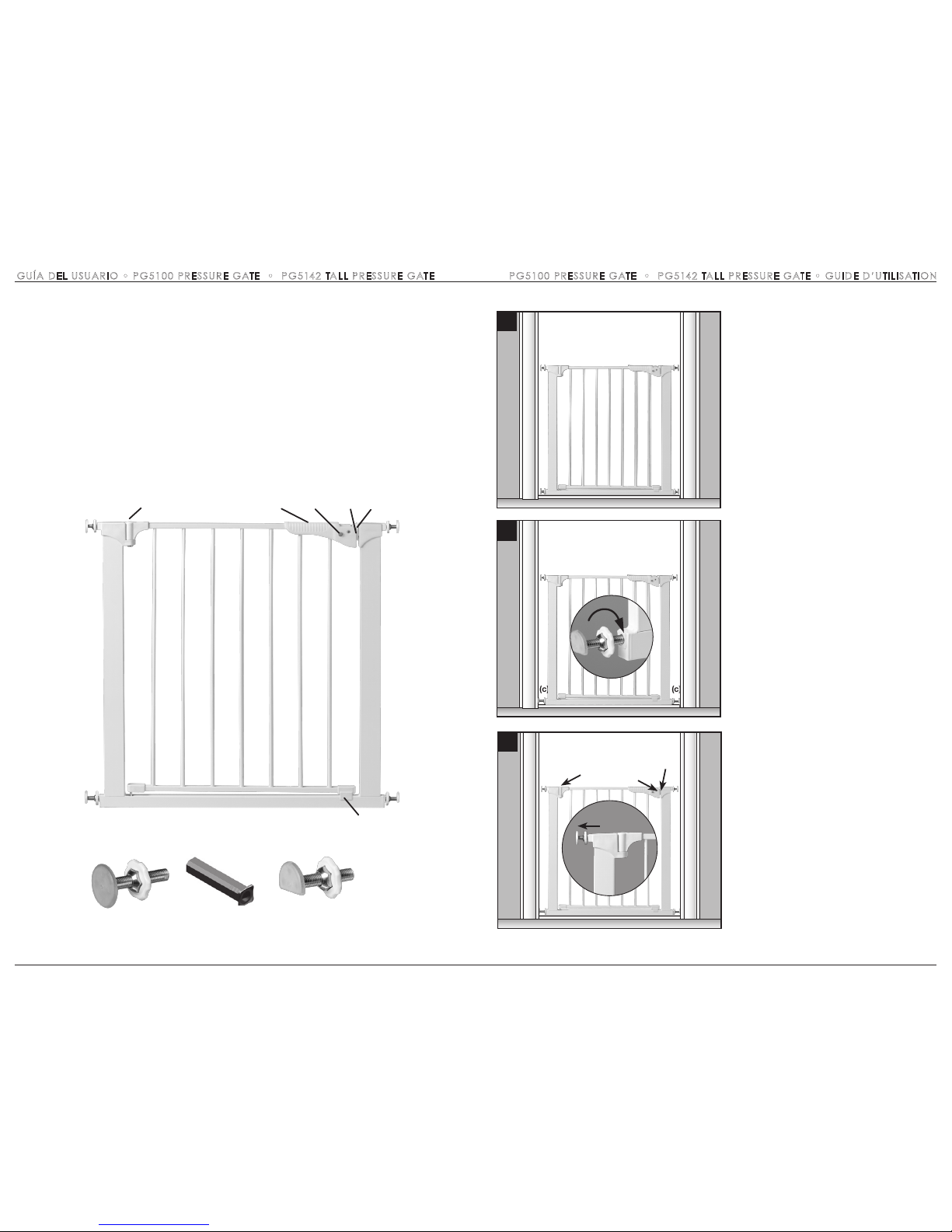
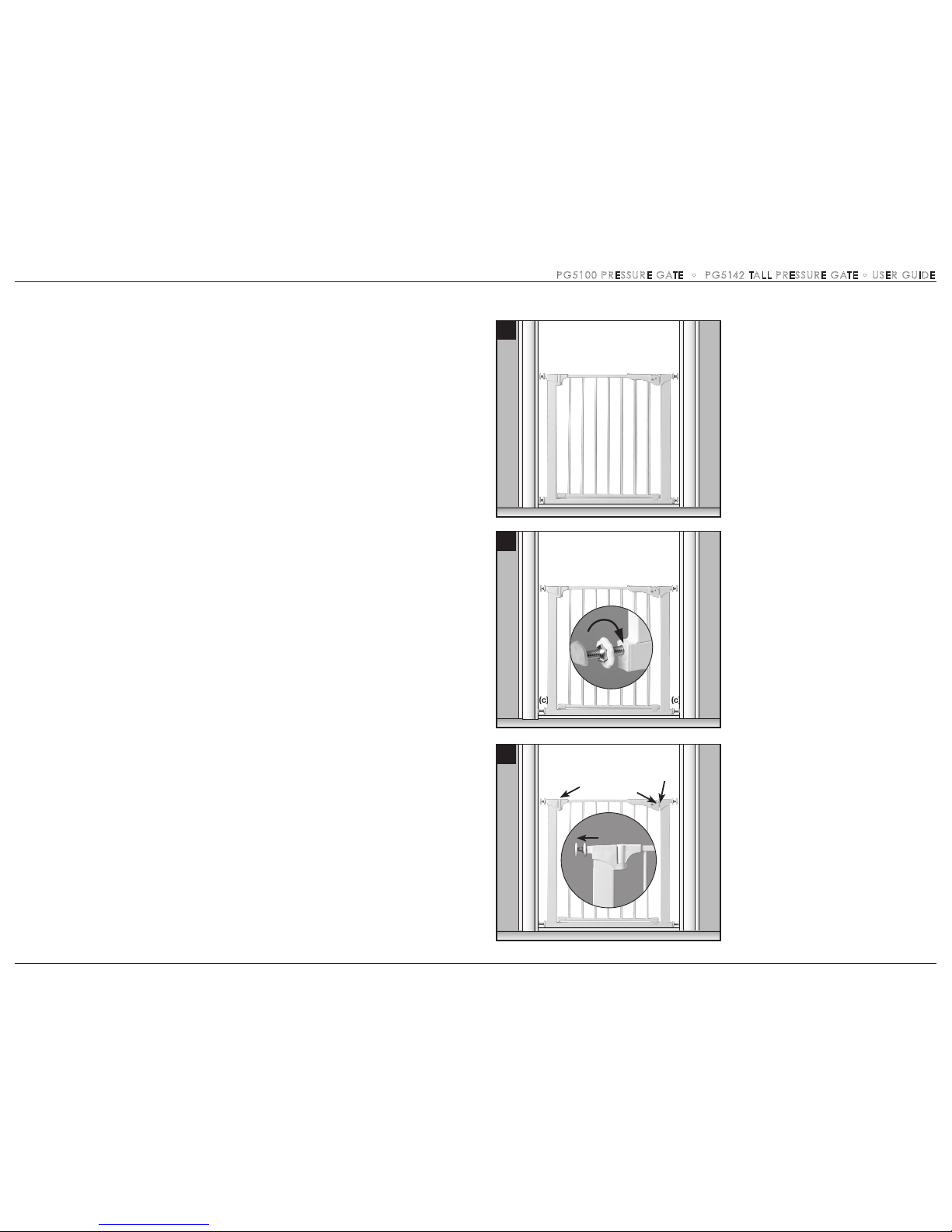
1 The gate must be installed in a
structurally sound opening. Never install
between two railings or two stair posts.
Ensure mounting surface (wall, doorframe,
etc.) is strong, rigid and is smooth, clean
and grease free. If mounting onto brick,
drywall or other surfaces, an optional gate
installation kit, wooden board mounted to
the surface or additional hardware may be
necessary to provide a solid, smooth
surface. Measure opening to determine if
extensions are needed. Correct width will
be reached by adjusting all 4 corner
spindles. Each spindle adjusts individually
and may be extended to varying lengths
(up to 1 ¾” each) to allow for molding,
uneven walls, etc. This gate can be used
in a closed doorway.
2 Spindle attachment is different
when using optional extensions and
when not using extensions. Spindle
housings are not used if square extension
tubes are required. If the housings have
been inserted, remove with a screwdriver.
3 Slide top spindles (a) and bottom
spindles (c) into spindle housing end (b).
Push assembly into gate corners.
Installation
1
(a) (b) (b) (a)
(c) (b) (b) (c)
3
2
PAGE LEFT BLANK INTENTIONALLY

6
7 Pull out upper spindle (a) on the handle
side until tension is reached and the
distance between the pressure plate (f)
and pressure hinge (d) is
1
/32”.
8 Close handle and check all hardware.
Tighten handwheels TOWARD GATE
FRAME. If correctly installed gate should
be firmly in place. Once opened, the
walk-through door should operate easily
in either direction.
9 a) To Open Gate- Release locking
mechanism by pressing buttons (e) in while
lifting handle. BUTTONS MUST ALWAYS BE
PRESSED IN WHEN LIFTING HANDLE. Lift
walk through door so hinge is raised and
door will swing open in either direction.
b) To Close Gate-Lift walk through door.
Align pressure hinge (d) and pressure plate
(f). Lower door and press handle (g) down
to lock.
8
1
/32”
(a)
(f) (d)
Flush
7
19
10 Instalación: KidCo tiene disponibles
pivotes Y OPCIONALES (Modelo GY-1) para
asistir en la instalación cuando la superficie
de montaje tiene un balaustre redondo.
Estos ejes se usan en lugar de los que se
incluyen con la reja básica. Se pueden pedir
en una concesionaria Command de su
localidad o directamente de KidCo. Retire la
ruedecilla de la tuerca del pivote de la reja, e
instálela en la tuerca del pivote en Y antes
de instalar el pivote en Y en el extremo de la
reja.
10
USER GUIDE • PG5100 PRESSURE GATE • PG5142 TALL PRESSURE GATE PG5100 PRESSURE GATE • PG5142 TALL PRESSURE GATE • GUÍA DEL USUARIO
9
(a)
(h)
(f)
(d)
6
PG5100 PRESSURE GATE • PG1542 TALL PRESSURE GATE • GUÍA DEL USUARIO
17
8
A
C
B
A Axe supérieur (2)
B Boîtier d'axe (4)
C Axe inférieur (2)
D Charnière à pression
E Bouton (2)
F Plaque de pression
G Poignée
H Charnière
I Repère
Liste des pièces
GH
I
EDF
4 Centre la reja en la abertura con el riel
inferior descansando en el piso. El espacio
en cada lado debe ser igual.
IMPORTANTE: La reja debe estar nivelada
y recta, desde arriba hacia abajo, puesto
que de lo contrario la puerta de cierre de la
reja no funcionará correctamente.
5 Jale hacia afuera los dos pivotes
inferiores (c) hasta que toquen la superficie
de montaje y descansen sobre la moldura
del piso (si es aplicable). Apriete las
ruedecillas HACIA EL MARCO DE LA REJA
al máximo valor posible. Cada eje se ajusta
individualmente y se puede extender a
varias longitudes para adaptarse a las
molduras, paredes irregulares, etc.
6 Cierre la puerta de acceso para que la
placa de presión (f) quede alineada con
la bisagra de presión (d). Hale hacia afuera
el pivote superior (a) del lado de la
bisagra (h) hasta que toque la superficie
de montaje. Apriete la ruedecilla HACIA
EL MARCO DE LA REJA.
5
6
(c) (c)
4
5
(c) (c)
GUIDE D’UTILISATION • PG5100 PRESSURE GATE • PG5142 TALL PRESSURE GATE

10
15
Información importante
SIGA CUIDADOSAMENTE ESTAS INSTRUCCIONES Y CONSÉRVELAS
PARA SU REFERENCIA FUTURA
La reja está diseñada para mascotas y niños de 6 a 24 meses de edad. Debido a que cada niño desarrolla
destrezas a diferentes edades, estos parámetros se deben ajustar al desarrollo particular de su hijo.
Ninguna pieza de la reja requiere lubricación. Limpie con agua jabonosa tibia o con un paño húmedo.
No use limpiadores abrasivos ni blanqueador. Una vez instalada la reja se debe revisar periódicamente
para asegurar un ajuste firme y seguro y mantenerla funcionando adecuadamente.
Mantenimiento
Diseñada para usarse con mascotas
y niños de 6 a 24 meses de edad.
Revise la estabilidad de la reja y
apriete regularmente todo el herraje
y los accesorios de montaje.
Para evitar una lesión grave o la
muerte, instale con seguridad la reja
o el corral y úselos de acuerdo con
las instrucciones del fabricante.
Nunca use estos productos para un
niño que se pueda subir a ellos o
abrir la reja o el corral.
Nunca use la reja si su altura es
menor que 3/4 partes de la estatura
del niño.
No use la reja si alguna de sus
partes falta o está rota.
El producto no necesariamente
evitará todos los accidentes.
Nunca deje al niño desatendido.
Use sólo piezas de repuesto
de Command™.
Nunca permita que el niño se suba
o se columpie en la reja.
Use la reja sólo con el mecanismo
de cierre firmemente asegurado.
Nunca use la reja en la parte
superior de las escaleras.
No use la reja si alguna de sus
piezas está dañada.
Nunca se pase sobre la reja.
Nunca cuelgue ni amarre juguetes
u otros objetos a ninguna parte
de la reja.
ADVERTENCIA
Installation
1
La barrière doit être installée dans une
ouverture structurellement solide. Ne jamais
l'installer entre deux rampes ou montants
d'escalier. S'assurer que la surface de
fixation (mur, embrasure de porte, etc.) est
solide, rigide et lisse, propre et sans graisse.
Si l'installation se fait sur de la brique, une
cloison sèche ou d'autres surfaces, un
ensemble d'installation de barrière en option,
une planche en bois fixée à la surface ou
une visserie supplémentaire pourra être
nécessaire pour donner une surface lisse
et solide. Mesurer l'ouverture pour
déterminer si des rallonges sont nécessaires.
La largeur correcte sera atteinte en ajustant
les 4 axes de coin. Chaque axe se règle
individuellement à des largeurs diverses
(4,4 cm max.) en fonction des moulures,
irrégularités des murs, etc. Cette barrière
peut être utilisée dans une embrasure de
porte fermée.
2
La fixation des axes est différente
selon que l'on utilise des rallonges en
option ou non.
Les boîtiers d'axe ne sont
pas utilisés si des tubes d'extension carrés
sont requis. Si les boîtiers ont été insérés,
les retirer avec un tournevis.
3
Glisser les axes supérieurs (a) et
inférieurs (c) dans l'extrémité du boîtier qui
leur est réservée (b). Pousser l'ensemble
dans les coins de la barrière.
1
(a) (b) (b) (a)
(c) (b) (b) (c)
3
2
GUIDE D’UTILISATION • PG5100 PRESSURE GATE • PG5142 TALL PRESSURE GATE PG5100 PRESSURE GATE • PG5142 TALL PRESSURE GATE • GUÍA DEL USUARIO

13
10 Aide d'installation – KidCo propose
des axes EN OPTION (modèle GY-1) pour
faciliter l'installation lorsque la surface de
fixation a un balustre arrondi. Ces axes
remplacent ceux qui sont fournis avec la
barrière de base. Ils se commandent auprès
d'un revendeur Command ou directement
auprès de KidCo. Enlever le volant de l'écrou
d'axe de la barrière et l'attacher à l'écrou
d'axe en Y avant d'installer l'axe en Y dans
l'extrémité de la barrière.
10
12
7 Tirer sur l'axe supérieur (a) côté
poignée jusqu'à ce que la tension soit
atteinte et que la distance entre la plaque
de pression (f) et la charnière de pression
(d) soit de 0,8 mm.
8 Fermer la poignée et vérifier toute la
visserie. Serrer le volant VERS LE CADRE
DE LA BARRIÈRE. Si la barrière est
correctement installée, elle doit tenir
fermement en place. Une fois ouvert, le
portail doit fonctionner facilement dans
l'une et l'autre direction.
9 a) Pour ouvrir la barrière : Relâcher le
mécanisme de verrouillage en appuyant
sur les boutons (e) tout en soulevant la
poignée. IL FAUT TOUJOURS APPUYER SUR
LES BOUTONS TOUT EN SOULEVANT LA
POIGNÉE. Soulever le portail pour
rehausser la charnière et ouvrir le portail
dans l'une ou l'autre direction.
b) Pour fermer la barrière : Soulever le
portail. Aligner la plaque de pression (f) sur
la charnière de pression (d). Abaisser la
porte et pousser la poignée (g) vers le bas
pour verrouiller.
8
0.8 mm
(a)
(f) (d)
Affleurant
7
PG5100 PRESSURE GATE • PG5142 TALL PRESSURE GATE • GUIDE D’UTILISATIONGUIDE D’UTILISATION • PG5100 PRESSURE GATE • PG5142 TALL PRESSURE GATE
9
(a)
(h)
(f)
(d)
6
14
A
C
B
A Eje superior (2)
B Cubierta para pivotes (4)
C Eje inferior (2)
D Bisagra de presión
E Botón (2)
F Placa de presión
G Manija
H Bisagra
I Localizador
Lista de piezas
GH
I
EDF
11
4 Centrer la barrière dans l'ouverture,
avec le rail inférieur en appui par terre. Les
espaces de chaque côté doivent être de
longueur identique. IMPORTANT : La
barrière doit être installée de niveau et au
carré sur la hauteur et sur la largeur, sinon
sa porte à fermeture ne fonctionnera pas
correctement.
5 Tirer vers l'extérieur sur les deux axes
inférieurs (c) jusqu'à ce qu'ils touchent la
surface de montage et reposent sur le haut
de la moulure du plancher (le cas échéant).
Serrer les volants VERS LE CADRE DE LA
BARRIÈRE le plus possible. Chaque axe se
règle individuellement à des largeurs
diverses en fonction des moulures,
irrégularités des murs, etc.
6 Fermer le portail pour aligner la plaque
de pression (f) sur la charnière de pression
(d). Tirer sur l’axe supérieur (a) côté
charnière (h) jusqu’a ce qu’il touche la
surface de fixation. Serrer le volant VERS LE
CADRE DE LA BARRIÈRE.
5
6
(c) (c)
4
5
(c) (c)
PG5100 PRESSURE GATE • PG5142 TALL PRESSURE GATE • GUIDE D’UTILISATIONGUÍA DEL USUARIO • PG5100 PRESSURE GATE • PG5142 TALL PRESSURE GATE

9
Prévue pour les animaux de
compagnie et les enfants âgés
de 6 mois à 24 mois
Vérifier la stabilité de la barrière
et resserrer régulièrement toute
la visserie et les supports
Pour éviter les blessures graves
ou la mort, installer solidement
la barrière ou l'enclos et utiliser
conformément aux instructions
du fabricant
Ne jamais utiliser avec un enfant
capable de grimper par-dessus la
barrière ou l'enclos ou de les
déloger ou les ouvrir
Ne jamais utiliser si la barrière
mesure moins des ¾ de la
hauteur de l'enfant
Ne pas utiliser si une pièce de la
barrière est cassée ou manquante
Le produit n'évitera pas
nécessairement tous les
accidents. Ne jamais laisser
un enfant sans surveillance
Utiliser uniquement les pièces
proposées par Command™
Ne jamais laisser un enfant
grimper ou se balancer sur
la barrière
Utiliser uniquement avec le
mécanisme de verrouillage
bien enclenché
Ne jamais utiliser la barrière
en haut d'un escalier
Cesser d'utiliser si une pièce de
la barrière est endommagée
Ne jamais grimper sur la barrière
Ne jamais suspendre ni attacher
de jouets, etc., sur quelque partie
de la barrière que ce soit
MISE EN GARDE
Informations importantes
SUIVRE ATTENTIVEMENT CES INSTRUCTIONS ET LES CONSERVER
À TITRE DE RÉFÉRENCE ULTÉRIEURE
Cette barrière de sécurité a été conçue pour les animaux de compagnie et les enfants âgés de 6 à 24 mois.
Comme les facultés de chaque enfant se développent à des âges différents, ces paramètres devront être
surveillés en fonction du développement de votre propre enfant.
Aucune pièce de la barrière n'exige de lubrification. Nettoyer avec de l'eau chaude et du savon ou avec un chiffon
humide. Ne pas utiliser de nettoyants abrasifs ou un agent blanchissant. Une fois installée, la barrière doit être
périodiquement vérifiée pour s'assurer de son ajustement sûr et de son bon fonctionnement.
Maintenance
16
1
La reja se debe instalar en una abertura
estructuralmente sólida. Nunca la instale
entre dos rieles ni entre dos postes de
escaleras. Asegúrese de que la superficie de
montaje (pared, marco de la puerta, etc.) sea
fuerte, rígida y lisa, limpia y sin grasa. Si se va
a montar sobre ladrillo, muro seco u otras
superficies, es posible que sea necesario un
juego opcional de instalación de la reja, una
tabla de madera montada en la superficie o
herraje adicional para proporcionar una
superficie sólida y lisa. Mida la abertura para
determinar si se necesitan extensiones.
El ancho correcto se puede lograr ajustando
los 4 ejes de las esquinas. Cada eje se
ajusta individualmente y se puede extender
a varias longitudes (hasta 1 ¾” cada uno)
para adaptarse a las molduras, paredes
irregulares, etc. Esta reja se puede usar en
un pasillo cerrado. Nunca use la reja en la
parte superior de las escaleras.
2
La instalación del eje es diferente
cuando se usan extensiones opcionales
y cuando no se las usa.
Si es necesario
usar tubos de extensión cuadrados, no
deben usarse las cubiertas para pivotes.
Si se insertaron cubiertas, quítelas con un
destornillador.
3
Deslice los ejes superiores (a) y los ejes
inferiores (c) en el extremo de la caja del eje (b).
Presione el conjunto en las esquinas de la reja.
Instalación
1
(a) (b) (b) (a)
(c) (b) (b) (c)
3
2
PG5100 PRESSURE GATE • PG5142 TALL PRESSURE GATE • GUIDE D’UTILISATIONGUÍA DEL USUARIO • PG5100 PRESSURE GATE • PG5142 TALL PRESSURE GATE
7
10 Installation Aid - KidCo has available
OPTIONAL Y-Spindles (model GY-1) to
assist in installation when the mounting
surface has a round baluster. These spindles
are used in place of the spindles included
with the basic gate. They may be ordered
through a local Command dealer or direct
from KidCo. Remove handwheel from gate
spindle nut and attach to Y spindle nut
before installing Y spindle into gate end.
10
18
7 Jale el eje superior (a) del lado de la
manija hasta que se sienta tensión y la
distancia entre la placa de presión (f) y la
bisagra de presión (d) sea de 1/32".
8 Cierre la manija y revise todo el herraje.
Apriete la ruedecilla HACIA EL MARCO DE
LA REJA. Si está correctamente instalada,
la reja debe estar firmemente en su lugar.
Una vez abierta, la puerta de acceso debe
operar fácilmente en cualquier dirección.
9 a) Para abrir la puerta: Libere el
mecanismo de bloqueo presionando los
botones (e) mientras levanta la manija. LOS
BOTONES SIEMPRE DEBEN ESTAR
PRESIONADOS AL LEVANTAR LA MANIJA.
Levante la puerta de acceso de manera
que la bisagra quede elevada y la puerta
se abrirá en cualquier dirección.
b) Para cerrar la reja levante la puerta de
acceso: Alinee la placa de presión (f) con la
bisagra de presión (d). Baje la puerta y
presione la manija (g) hacia el pestillo.
8
1
/32”
(a)
(f) (d)
Al ras
7
PG5100 PRESSURE GATE • PG5142 TALL PRESSURE GATE • USER GUIDEGUÍA DEL USUARIO • PG5100 PRESSURE GATE • PG5142 TALL PRESSURE GATE
9
(a)
(h)
(f)
(d)
6
WARRANTY • GARANTIE • GARANTÍA
20
KidCo® Limited Warranty
Your KidCo product is warranted to be free from manufacturing defects for a period of one year from date of purchase under normal non
commercial use and in compliance with the operating instructions. This warranty extends only to the original retail purchaser and is only valid
when supplied with proof of purchase. KidCo will either repair, or at our option replace, free of charge, any parts necessary to correct defects in
material or workmanship during the warranty period. This warranty is complete and exclusive. The warranty expressly disclaims liability for
incidental, special and consequential damages of any nature. Any implied warranty arising by operation of law shall be limited in operation to the
terms of this warranty. Some states do not allow the exclusion or limitation of incidental or consequential damages or limitations on how long an
implied warranty lasts, so the above may not apply to you. This warranty gives you specific legal rights, and you may have other rights which vary
from state to state.
Should Repair Or Parts Be Necessary
Should a repair be needed during the warranty period, ship the gate in the original carton or similar protective container (check any retail store or
purchase from UPS) and send freight prepaid (we suggest UPS) to: KidCo Inc., 1013 Technology Way, Libertyville, IL 60048-5349. Include a
note with your return address, day-time telephone number, and specify what is wrong with the product. Repairs can normally be made within 48
hours after receipt at KidCo. For additional information CALL our customer service department at (800) 553-5529.
Garantie Limitée KidCo
®
Votre produit KidCo est garantit contre tout défaut de fabrication pendant une période d’un an à partir de la date d’achat dans des conditions
normales d’utilisation non commerciale et conforme au mode d’emploi. Cette garantie est uniquement accordée à l’acheteur d’origine chez un
revendeur et elle est uniquement valable pour toute réclamation accompagnée d’un justificatif d’achat. KidCo réparera ou, à sa discrétion,
remplacera gratuitement toute pièce nécessaire pour corriger les vices de matériel ou de fabrication durant la période de garantie. Cette garantie
est complète et exclusive. Par cette garantie, KidCo rejette expressément toute responsabilité vis-à-vis de dommages accessoires, spéciaux et
indirects, quelle qu’en soit la nature. Toute garantie tacite par effet de la loi se limitera aux termes de cette garantie. Certaines provinces
n’autorisant pas l’exclusion ou la limitation de dommages accessoires ou indirects en rapport avec la durée d’une garantie tacite, il est possible
que ce qui précède ne vous concerne pas. Cette garantie vous accorde des droits légaux spécifiques et il est possible que vous ayez d’autres
droits, variables d’une province à l’autre.
Pour toute réparation ou pièce nécessaire
Si une réparation s’avère nécessaire durant la période de garantie, expédiez la barrière de sécurité dans son carton d’origine ou une boîte de
protection similaire (disponible auprès d’un revendeur ou vendue par UPS) et envoyez en fret payé d’avance (UPS suggéré) à: KidCo Inc.,
1013 Technology Way, Libertyville, IL 60048-5349. Incluez une note mentionnant vos adresse de retour et numéro de téléphone, et décrivez
la nature du problème. Les réparations sont normalement effectuées sous 48 heures après réception par KidCo. Pour plus
d’informations, REJOIGNEZ notre service clientèle au (800) 553-5529.
Garantía Limitada de KidCo
®
Se garantiza que su producto KidCo estará libre de defectos de fabricación por un período de un año a partir de la fecha de compra bajo
condiciones de uso normales y no comerciales y si se cumple con las instrucciones de operación. Esta garantía se extiende sólo al comprador
minorista original y sólo es válida cuando se proporciona con un comprobante de compra. KidCo gratuitamente reparará o reemplazará, a su
opción, cualquier pieza necesaria para corregir los defectos en los materiales o la mano de obra durante el período de la garantía. Esta garantía
es completa y exclusiva. La garantía expresamente renuncia a la responsabilidad por daños incidentales, especiales y resultantes de cualquier
naturaleza. Cualquier garantía implícita que surja del ministerio de la ley estará limitada en aplicación a los términos de esta garantía. Algunos
estados no permiten la exclusión ni la limitación de daños incidentales o resultantes ni las limitaciones en la duración de una garantía implícita,
de manera que lo antedicho puede no aplicar a usted. Esta garantía le confiere derechos legales específicos, y usted puede tener otros derechos
dependiendo del estado en donde resida.
Si se requiere reparación o piezas
Si se requiere la reparación de la reja durante el período de la garantía, empáquela en su caja original o en un recipiente protector similar (puede
conseguir uno en alguna tienda minorista o cómprelo en UPS) y envíela con porte prepagado (sugerimos UPS) a: KidCo Inc., 1013 Technology
Way, Libertyville, IL 60048-5349. Incluya una nota que contenga la dirección de devolución, un número telefónico de contacto durante el día y
especifique cuál es el problema con el producto. Normalmente las reparaciones se hacen en el transcurso de 48 horas después de que el
producto se recibe en KidCo. Si desea información adicional LLAME a nuestro Departamento de Servicio al Cliente al teléfono (800) 553-5529.
5
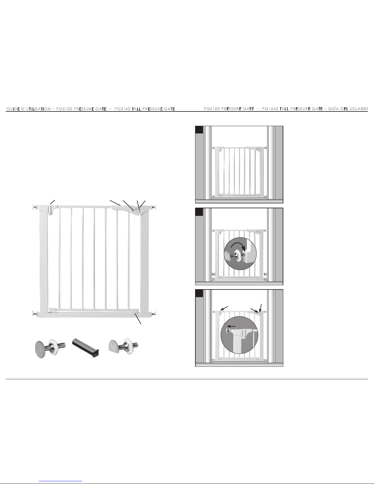
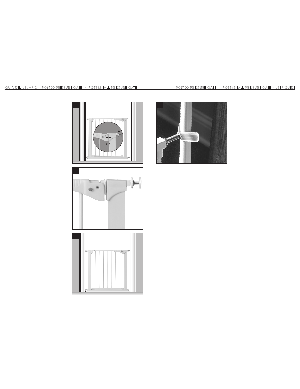
4 Center the gate in opening with bottom
rail resting on floor. Gaps on each side
should be equal. IMPORTANT: The gate
must be level and straight up and down,
otherwise the gate’s door will not
function properly.
5 Pull out the two bottom spindles (c)
until they touch the mounting surface and
rest on top of floor molding (if applicable).
Tighten handwheels TOWARD GATE
FRAME as tightly as possible. Each spindle
adjusts individually and may be extended
to varying lengths to allow for molding,
uneven walls, etc.
6 Close walk through door so pressure
plate (f) is aligned with pressure hinge (d).
Pull out the top spindle (a) on the hinge
side (h) until it touches the mounting
surface. Tighten handwheel TOWARD
GATE FRAME.
5
6
(c) (c)
4
5
(c) (c)
PG5100 PRESSURE GATE • PG5142 TALL PRESSURE GATE • USER GUIDE

3
Intended for use with pets and
children from 6 months through
24 months
Check the stability of the gate
and tighten all hardware and
mountings regularly
To prevent serious injury or death,
securely install gate or enclosure
and use according to manufacturer’s instructions
Never use with a child able to
climb over or dislodge/open the
gate or enclosure
Never use if gate is less than
¾ of child’s height
Do not use if any part of the gate
is broken or missing
This product will not necessarily
prevent all accidents. Never leave
child unattended
Use only spare parts available
from Command™
Never allow child to climb or
swing on gate
Use only with the locking/latching
mechanism securely engaged
Never use gate at top of stairs
Discontinue use if any part of
the gate is damaged
Never climb over the gate
Never hang or tie toys, etc,
to any part of the gate
•
•
•
•
•
•
•
•
•
•
•
•
•
•
WARNING
Important Information
FOLLOW THESE INSTRUCTIONS CAREFULLY AND KEEP THEM
FOR FUTURE REFERENCE
This gate is designed for pets and children from 6 months to 24 months. Since each child’s skills develop
at different ages, these parameters should be monitored against your child’s own development.
No part of the gate requires lubrication. Clean using warm, soapy water or a damp cloth. Do not use abrasive
cleaners or bleach. Once installed the gate should be checked periodically to ensure a safe and secure fit
and to maintain proper working order.
Maintenance
22
PG5100 PRESSURE GATE • PG5142 TALL PRESSURE GATE • USER GUIDE
CETTE PAGE EST INTENTIONNELLEMENT LAISSÉE EN BLANC
 Loading...