

Page 1
www.commproduct.com
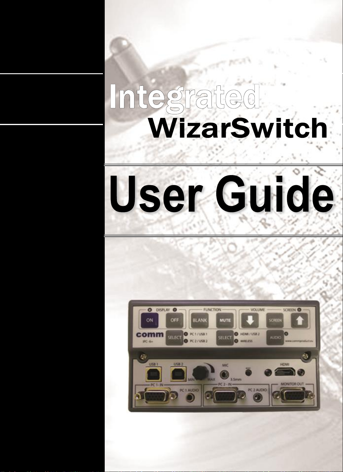
IPC-6+
Page 2

www.commproduct.com
Thank you for purchasing our COMM Integrated
Control Switches!
COMM Integrated Control Switches (IPC Series) - Designed to control your
Audiovisual Equipment in the most simplified ways via RS-232 commands;
reasonably priced and works with most projectors and plasma displays.
One Touch Selection with LED Back-Lit Indications on the selectors’ buttons,
you can easily control your displays with its various selector buttons (e.g.
select the different input source, volume and/or screen controls etc)
Built-In Signal Amplifiers of 250MHz / 350MHz bandwidths to minimize
signal-loss worries.
Widely used in Classrooms, Auditoriums, Lecture Theatres, Conference
Rooms etc.
MAIN FEATURES
• Display Controller for your Projector, Display
(Power ON/OFF, input source selections, volume control) via RS232
Commands
• One Touch Selection with LED Back-Lit Indications
• INPUTS :1 HDMI, 2 USB Type B , 2 VGA with 2 mini jack audio, 1 mini jack
Microphone
• OUTPUTS: 1 HDMI, 1 USB and 2 VGA
• Built-In VGA Selector and VGA Splitter
• Digital Volume Control for sound level adjustments
• Volume Control Knob for MIC Inputs sound adjustments
• Optional: Comm Contact Relay Module for Screen Control
• STANDBY mode - MIC Volume Control usable
• VGA Monitor Out - Monitor is usable even when projector is OFF
A
Page 3

www.commproduct.com
TABLE OF CONTENTS
1 Function Keys……………………….…..... 1
2 Internal Board Connections……….….... 2
3 Connections………………………….….… 3
3.1 HDMI Connections…………….….....3
3.2 Power Connections………………... 4
3.3 RS-232 Connections……………..... 5
3.4 Audio/VGA/ USB Connection ...…. 6
3.5 Contact Relay Module .................... 7
4 Specifications……………………..…….… 8
5 Standard Package……………………..…. 9
6 Troubleshooting……………….................10
7 Notes……………………………….………..11
8 Connections Diagram…………………… 12
B
Page 4
www.commproduct.com
1
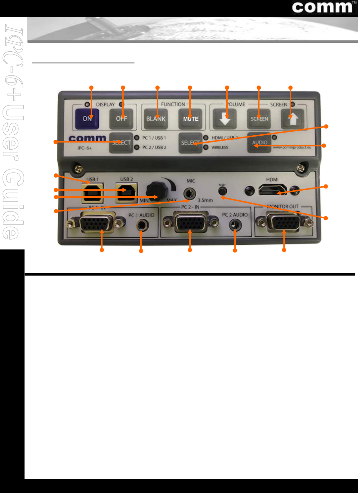
1. Function Keys
1 2 3 4 5 6
19
8
17
7
15
16
11
14 13
10
9
12
Model No: IPC-6+
1. Display ON
2. Display OFF
3. Picture Blank Toggle Button
4. Mute ON/OFF
5. Screen/ Volume Control DOWN
6. Screen Selector
7. Screen/ Volume Control UP
8. HDMI with USB 2 / Wireless
Selector
9. Audio Selector
10. HDMI Signal Input
11. HDMI Reset
12. VGA Signal Monitor Out
13. VGA 2 Signal and Audio Input
14. VGA 1 Signal and Audio Input
15. MIC In – 3.5mm
16. MIC Volume Control Knob
17. USB 2 Input
18. USB 1 Input
19. PC1 / USB1 or PC2 / USB2
Signal In Selector
18
13
14
Page 5
www.commproduct.com
1
4
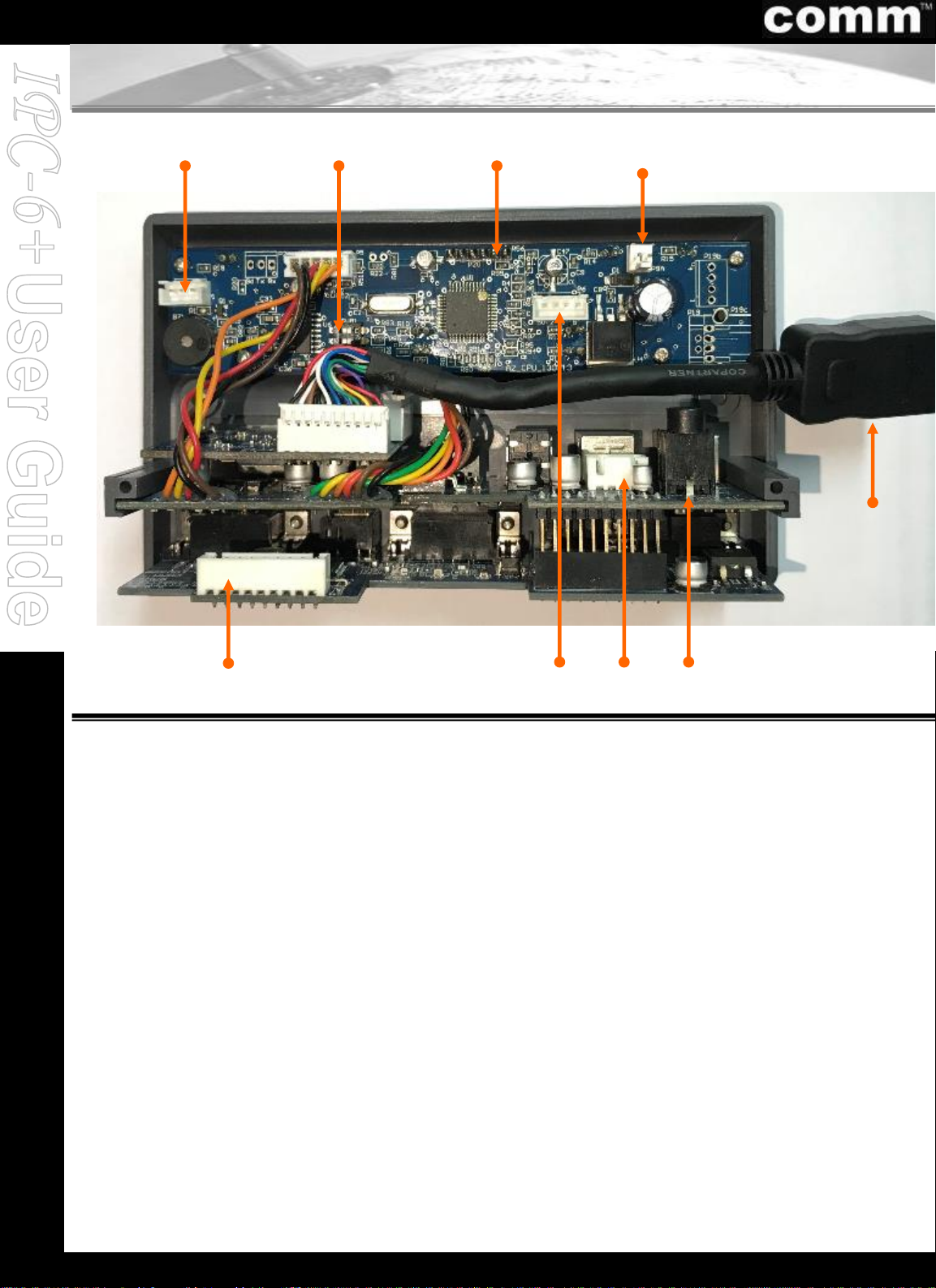
1. RS232 Connection
2. Dip-Switch Settings
3. Programming Connection
4. Power Connection
5. HDMI Connection
6. Mini Jack Audio Connection
7. USB Connection
8. Screen control (Optional CRM-1- contact relay
module)
9. VGA Connection
3
68
2
2. Internal Board Connections
2
5
79
Page 6

www.commproduct.com
1. HDMI (Female)
3.1. HDMI Connection
1
3
Page 7
www.commproduct.com
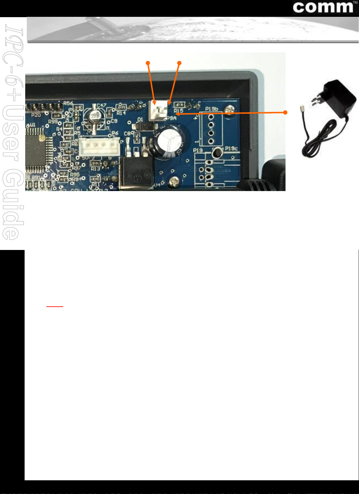
3.2. Power Connection
OR
2. Positive + on Power Adapter
3. Negative - on Power Adapter
1. Direct plug-in to 12V DC Power Adapter
(Power Adapter Supplied with every purchase)
1
2
3
4
Page 8
www.commproduct.com
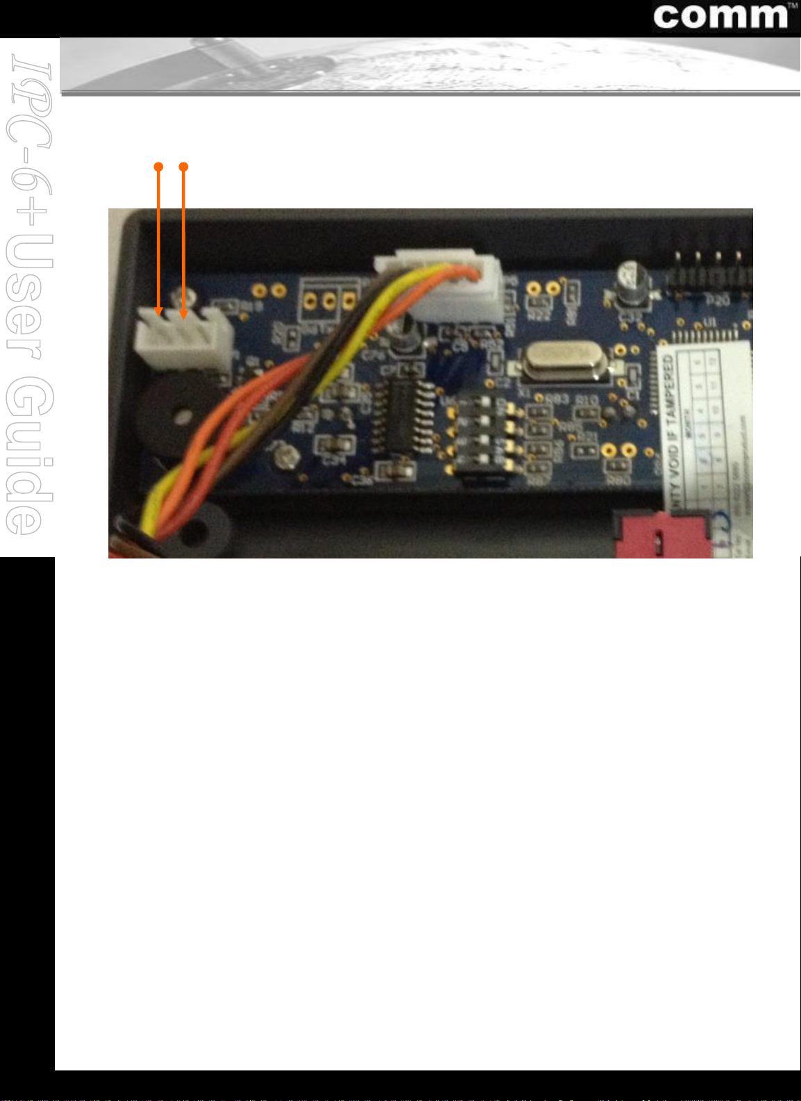
3.3. RS232 Connection
21
1.Ground (GND) – RS232 to Projector (GND)
2.Transmit (TX) – RS232 to Projector Received (RXD)
Please refer to Dip Switch Settings (Separate Appendix)
for the different projectors’ settings.
5
Page 9
www.commproduct.com
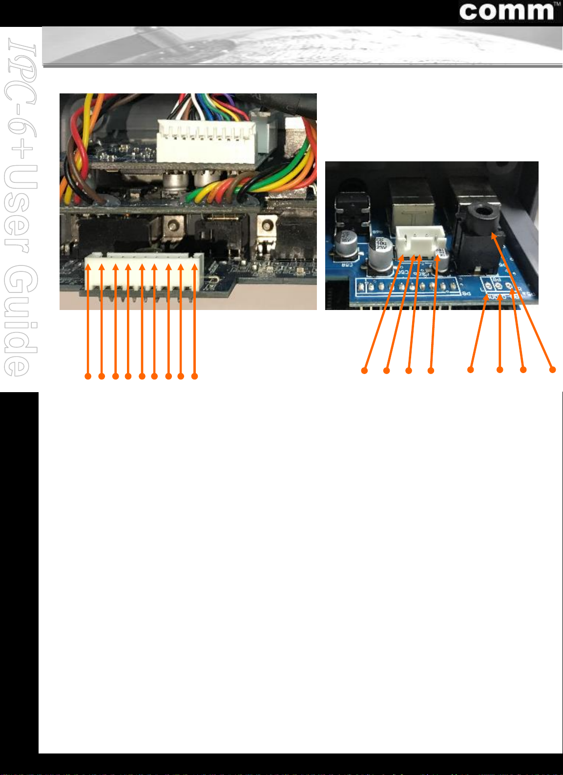
10 1112
10. Audio Left
11. Audio Right & Left Ground
12. Audio Right
13. Mini Jack Audio
14. GND (Black)
15. D - (Green)
16. D + (White)
17. VBUS Red
3.4. Audio, VGA & USB Connection
6
13
1 2 3 4 5 6 7 8 9
1. Red
2. Red Ground (GND)
3. Green
4. Green Ground
5. Blue
6. Blue Ground
7. H Ground (GND)
8. V Ground (GND)
9. H/V Ground (GND)
14 15 16 17
Page 10
www.commproduct.com
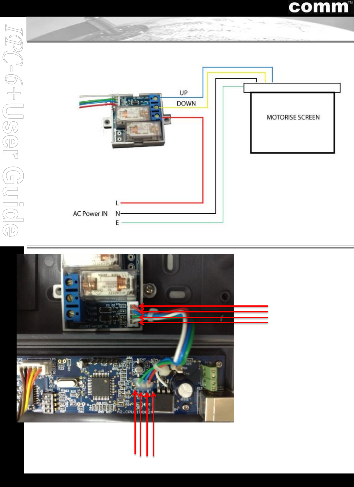
3.5. Contact Relay Module Connection
Contact Relay Module CRM-1
(Optional Item for Screen Control)
7
1
2
3
4
4 3 2 1
Connection:
1: Ground (Red)
2: UP (Blue)
3: Down (Green)
4: 5VDC (White)
Page 11
www.commproduct.com
All products information and specifications are subject to changes without prior notice.
4. Specifications
8
MODEL : IPC-6+
A) Input
• PC1 / PC2 Signal - VGA (D-Sub 15-Pin Female)
• PC1 / PC2 Audio - 3.5mm Mini Jack
• PC1 / PC2 USB - USB Type B (Selection together with VGA )
• HDMI Signal - HDMI
• Audio Signal - Stereo
• Microphone IN - 3.5mm Mini Jack
• USB - USB TYPE B
B) Output
• PC Signal - VGA Bandwidth of 250MHz
• PC Signal - Monitor OUT, VGA Bandwidth of 250MHz
• HDMI Signal
• Audio Signal
• Microphone
• USB - 1 USB to interactive board or projector
C) Communication Control
• Serial Control Port - RS232
• Baud Rate - 9600, 19200, 38400, 115200
• Data / Stop Bits - 8 bits / 1 stop bit, No parity
- Programmable to 2 stop bit and EVEN parity
D) Selector Switch (with LED Back-Lit Indications)
• Display ON/OFF
• Blank (Toggle Button)
• Mute (Toggle Button)
• SCREEN/ AUDIO VOLUME (UP / DOWN) (for Screen or PC & HDMI Audio)
• VGA IN Selector (Switch between PC1 with USB 1 or PC2 with USB 2 Input)
• HDMI/ WIRELESS IN Selector (depend of device which got wireless on projector)
• AUDIO Selector (Select to adjust Audio volume control)
• VOLUME Control Knob (For MIC Inputs)
• HDMI Reset Button
E) Power Supply
• 12V DC 500mA Power Adapter
F) Product Dimension & Weight
• Unit Dimension (W x H x D) : 14.5cm x 8.6cm x 5.5cm (5.7” x 3.4” x 2.2”)
• Unit Weight : 0.25 kg (0.55 lbs)
• Box Dimension (W x H x D) : 27.7cm x 10cm x 7cm (10.9” x 4” x 2.6”)
• Weight (Incl. Power Adapter) : 0.64 kg (1.41 lbs)
Page 12
www.commproduct.com
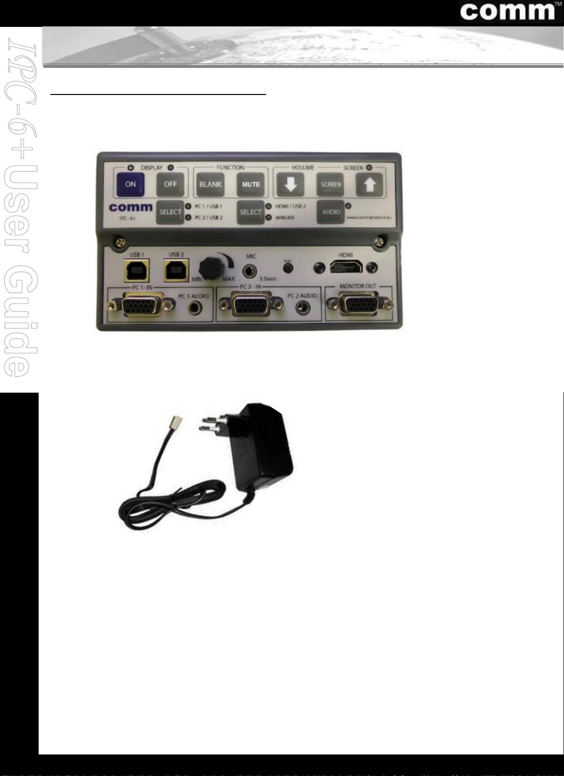
5. Standard Package
Consists of the following:
(1) Integrated Control Switcher Unit
(2) 12V DC 500mA Power Adapter
9
Page 13
www.commproduct.com
6. Troubleshooting
Problem Solution
I have connected the power adapter to the
control switch but there are still no LED
lights indications on the control switch.
1. Check the positive & negative on the power adapter
is soldered at the right connection.
(See page 4)
2. Verify the voltage of the power adapter is in
accordance to your country current power voltage
input
I have soldered the RS232 connections to
the projector/plasma control port, but still
unable to control the switch accordingly.
1. Make sure the RS232 GND and TX soldering
connections are soldered on the right pin on the
controller PCB Board.
(See page 6)
2. Check the RS232 connection settings on the
projector/plasma for the correct baud rates or Pin
Configurations. There may be a need to change
the default baud rate setting on your projector/
plasma, if required.
(See page 6)
3. Reprogramming is required.
(Please refer to the programming manual)
4. Check RS232 connector is that short circuit.
Flickering images projected out after the
connections to the control switch.
1. Make sure the RGB Soldering connections on the
Horizontal and Vertical is soldered correctly.
(See page 3)
One of the colors projected out is missing,
or the colors are washed off.
1. Make sure the RGB Soldering connections on the
Red, Green and Blue is soldered correctly.
(See page 3)
If all the LED are lighted up on the control
switch.
1. Reprogramming is required.
(Please refer to the programming manual)
If there are “Hissing” sound problem from
your Active Speakers.
1. This is a high Gain pre-Amp switcher, Please turn
down the Speaker Volume and Control Volume
up/down by switcher
If these troubleshooting tips do not solve your problems, please email us at [email protected]
or call us at (+65) 6515 1043.
10
Page 14

www.commproduct.com
7. Notes
1. Please remember to switch OFF IPC switcher’s POWER
ADAPTER during the soldering process or connection
with the relay contact module
11
Page 15
www.commproduct.com
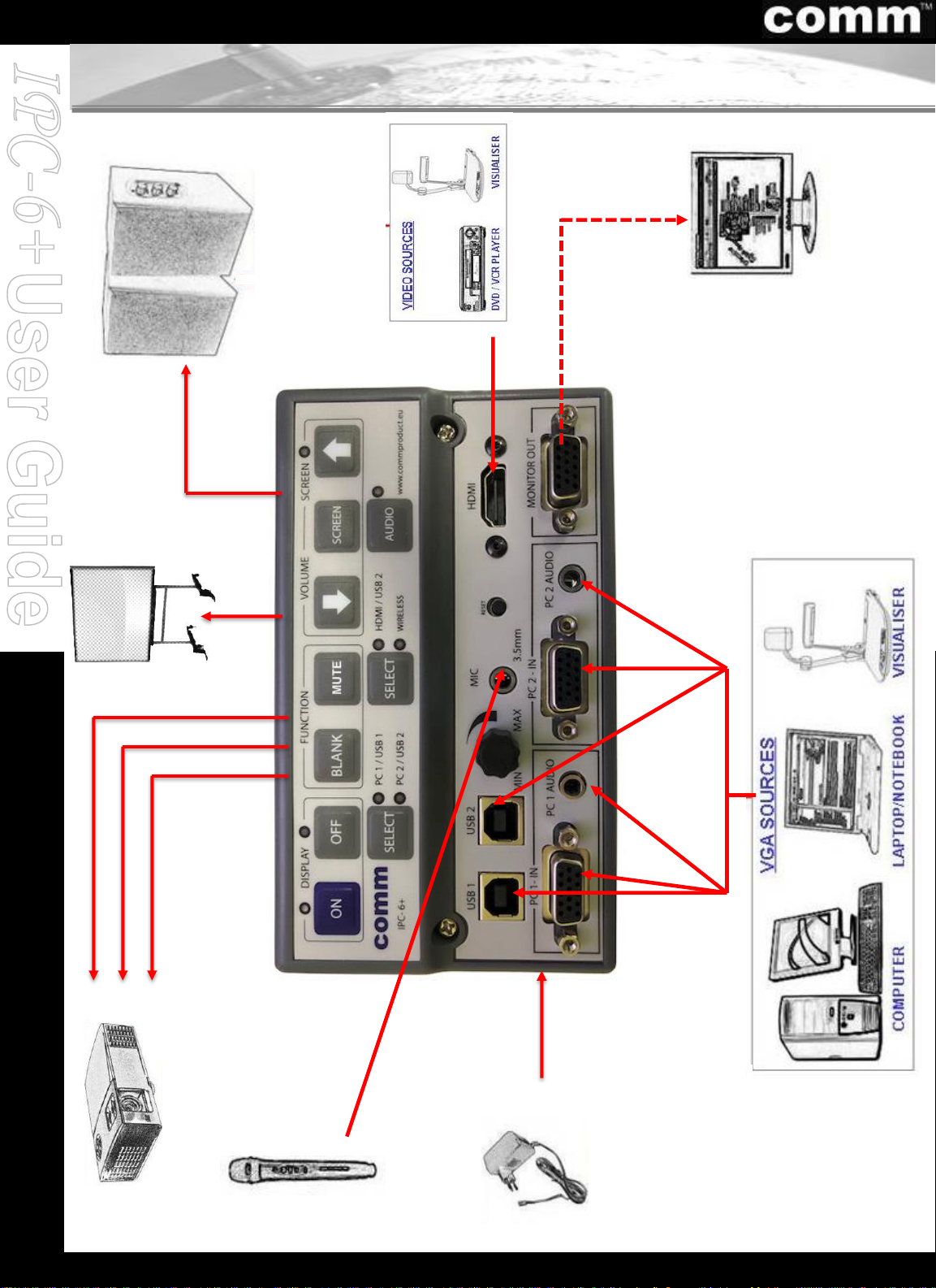
8. Connection Diagram
12
POWER ADAPTER
VGA
1 Signal
with AUDIO
and USB IN
VGA Cable
RS232 cable
(TX and GND)
Power Supply
PROJECTOR
MULTIMEDIA
SPEAKER
COMM IPC
-6+
WIZARSWITCH
MONITOR
Monitor
OUT
(VGA OUT)
MIC IN
MICROPHONE
Audio
OUT
(Left/Right
)
VGA
2 Signal
with AUDIO
and USB IN
INTERACTIVE
BOARD/
PROJECTOR
USB
Cable
HDMI
IN
HDMI
Cable
Page 16
www.commproduct.com
For additional information, please contact us at:
Customer Care HelpDesk: [email protected]
All products information and specifications are subject to changes without prior notice.
Last updated as at 01-Nov-2018
© Comm Products Technologies Pte Ltd – 2018
13
 Loading...