

Page 1
© 2016
ALLIED AIR ENTERPRISES
215 METROPOLITAN DR.
WEST COLUMBIA, SC 29170
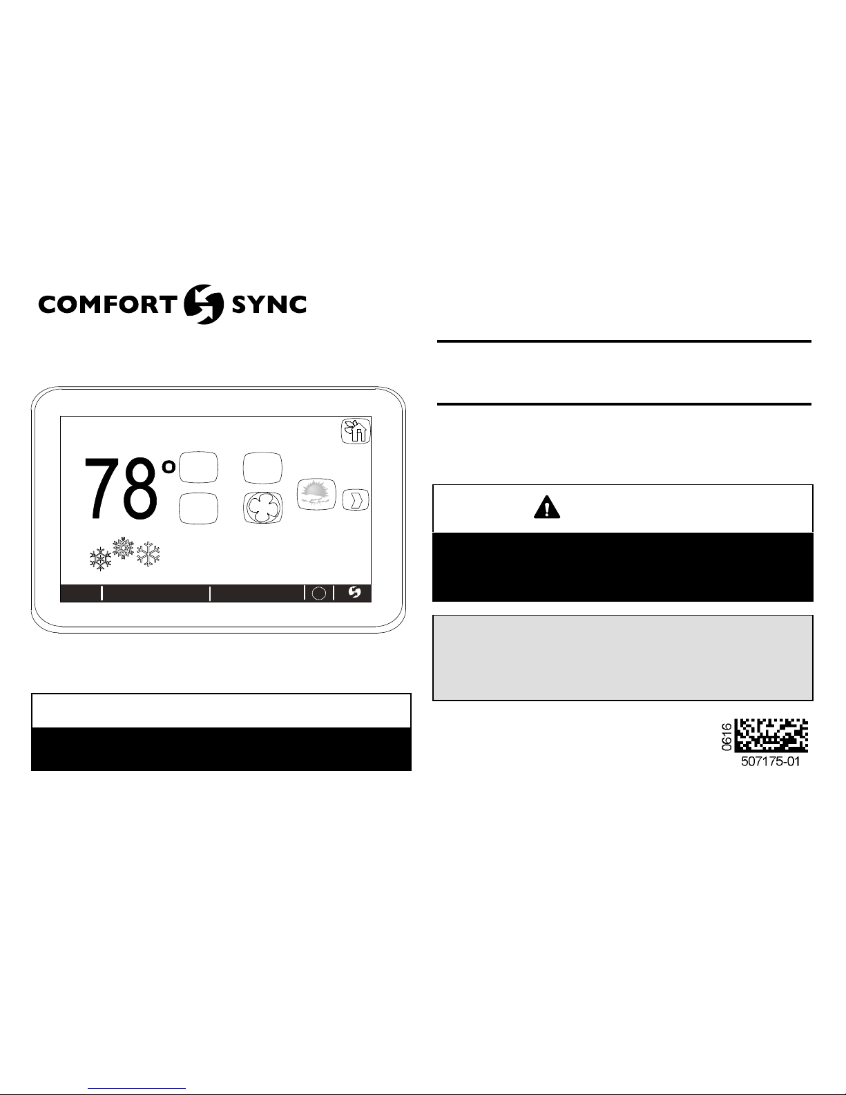
indoor temperature
indoor humidity is 41%
cool-to
set temp
75
heat to
72
spring ...
program
is on
outdoor
temperature
80
system is cooling
forecast
Hi 85
Lo 60
9:39 am Aug 15, 2012
Wi-Fi
enter
away
?
fan is
OFF
fan is
AUTO
THIS MANUAL MUST BE LEFT WITH THE HOMEOWNER
FOR FUTURE REFERENCE
NOTICE
Read this manual before programming this thermostat.
Use this thermostat only as described in this manual.
INSTALLER'S SYSTEM SETUP
GUIDE
Comfort Sync Thermostat
Touchscreen Programmable Communicating Thermostat
CONTROLS
507175-01
6/2016
Supersedes 3/2016
WARNING
Improper installation, adjustment, alteration, service or maintenance
can cause property damage, personal injury or loss of life.
Installation and service must be performed by a licensed professional
HVAC installer (or equivalent) or service agency.
Comfort Sync-Enabled Units
A80DS2V A80US2V2 A96DS2V A96US2V
A97DSMV A97USMV BCE4M_S BCS2M_S
4SCU16LS 4SCU18LS 4SCU20LX 4SHP16LS
4SHP18LS 4SHP20LX
Page 2
2
TABLE OF CONTENTS
Comfort Sync Thermostat - Technical Description and Features 2...
Installation and Setup 3........................................
Adjusting System Settings 4....................................
Establishing Wi-Fi and Internet Connections 5.....................
Troubleshooting Wi-Fi 5........................................
Account Registration 8.........................................
Firmware Update 9............................................
Adding Non-Communicating Outdoor Unit and Accessories 9.........
Outdoor Unit (Air Conditioner or Heat Pump) 9....................
Bypass (24VAC) Humidifier 9...................................
Auxiliary Dehumidifier 10......................................
Adjusting Humidification and Dehumidification Settings 10...........
Using the Tests / Diagnostics Features 12..........................
Alert Codes 14.................................................
Wiring Diagrams 27.............................................
Secure Web Portal 30...........................................
Screen-saver 30................................................
Accessing Installer Screens and Changing Equipment Parameters 31..
WARNING
This is a 24VAC Class 2 thermostat. Do not install on voltages higher
than 30VAC.
Do not switch system to cool if the outdoor temperature is below 45°F
(7°C). This can damage the cooling system.
Shipping and Packing List
1 - Comfort Sync Thermostat 4 - Mounting Screws
4 - Wall Anchors
1 - Homeowner's Manual
1 - Warranty Card
Comfort Sync Thermostat - Technical Description and
Features
The 24VAC Comfort Sync thermostat is an electronic communicating,
color display touchscreen and 7-day programmable thermostat. It stores
system parameters and settings in non-volatile memory (i.e., it retains data
when electrical power fails or is turned off).
The Comfort Sync thermostat can connect to online services via the
Internet through the homeowner's Wi-Fi access point. After online
registration is completed, the system may then be accessed by the
homeowner from anywhere using a remote Internet connection via computer
or personal communicating device.
Refer to page 27 for information on making connections to the thermostat.
Page 3
Comfort Sync 7-Day Programmable Communicating Thermostat
3
This thermostat supports:
Wireless bands 802.11b, 802.11c and 802.11n
Three languages (English, French, Spanish)
Air conditioning or heat pump units with up to four stages of heat / two
stages of compressor operation (2 stages of heat pump heating, 2
stages of auxiliary back-up heating and 2 stages of emergency
heating)
Multiple-stage heat / cool and universal compatibility
(gas/electric/heat pump/air conditioner).
Dual-fuel capable (Comfort Sync-enabled HP only) with two balance
points.
Indoor air quality with time‐based notification of consumables
including media filters, UVC bulbs and humidifier pads.
Humidification measurement and control.
Dew point adjustment control
Multiple-stage HVAC systems
Equipment maintenance reminders
Autochangeover mode -- Permits control of heating, cooling,
humidification, and dehumidification without user involvement
OUTDOOR TEMPERATURE SENSOR
All Allied branded communicating outdoor units contain a built-in outdoor
temperature sensor.
Installation and Setup
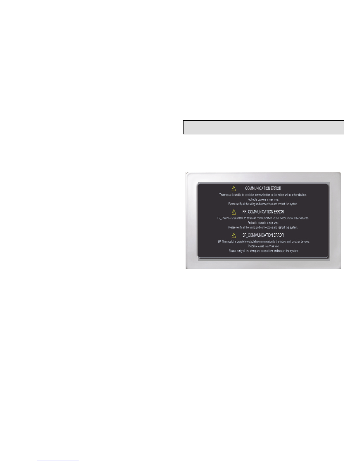
COMMUNICATION ERROR SCREEN
During initial thermostat start-up if the following screen appears (see figure
1), this will indicate that the thermostat has been incorrectly wired or has
shorted wires. Turn power off to the system and verify that all wiring is
correct.
Figure 1. Communication Error Screen
Page 4
4
Adjusting System Setting
SET TIME AND DATE
Use the arrows to select Time and Date; touch edit to proceed to the “Set
current time and date” screen.
When “Time and Date” screen appears, enter the correct date as follows:
Use the left and right arrows to change the month and year.
Touch a day of the month to select it.
Touch on the hour or minute; up down arrows appear to allow change.
Touch the am/pm field to toggle it between am and pm.
When the correct date and time is set, touch save to save settings and
return to previous settings screen.
Touch next to continue to next screen.
CIRCULATE FAN ON TIME SETTING
“Circulate” is enabled on the user's home screen or system settings page.
It keeps air circulating from 15% to 50% percent of time. The following
settings approximate how long the fan will run at these typical settings:
15% (9 minutes fan run time per hour)
25% (15 minutes fan run time per hour)
35% (21 minutes fan run time per hour)
45% (27 minutes fan run time per hour).
NOTE - If the circulate fan mode is on, a timer is set to measure all the time
that the fan is blowing, regardless if it is running to deliver heating or cooling
or just for air circulation.
The following table lists all of the installer configurable system level
parameters available from the installer setup screens. After adjusting
system settings, select next to continue.
Table 1. System Settings
Parameter
Name
Default
Parameter Value
Setting
Increment
Time and Date —
(Time/date elements
screen)
—
Daylight Saving
Time
Enabled Enabled, Disabled —
Circulate Fan
ON Time
35% Range 15 to 45% 1%
Temperature
Unit
Fahrenheit Fahrenheit or Celsius —
System Name —
(keyboard input
screen)
—
Dealer Name Allied
(keyboard input
screen)
Note: When adding
the dealer number, all
other dealer fields will
auto populate once
thermostat registra
tion is completed.
—
Dealer Address — —
Dealer Phone —
Dealer Email — —
Dealer Website —
Page 5
Comfort Sync 7-Day Programmable Communicating Thermostat
5
Establishing Wi-Fi and Internet Connections
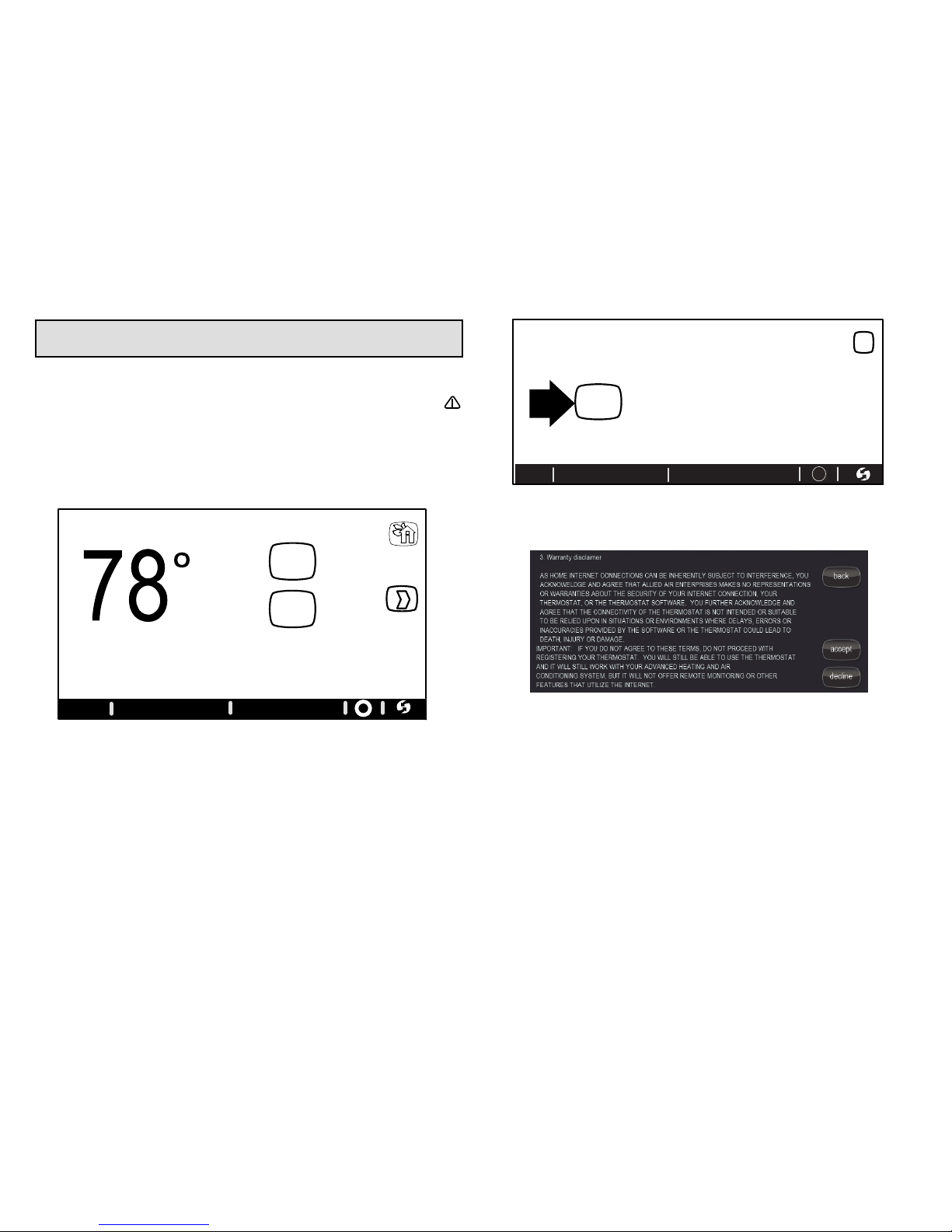
WI-FI ROUTER CONNECTIVITY
(Thermostat to homeowner's Wi-Fi router). “Wi-Fi” in the bottom left corner is
the “button” used to access the Wi-Fi settings screen. “Wi-Fi” with a
beneath it indicates a prior connection to the server has been lost. If a
connection had been lost, then re-established, the triangle goes away. Wi-Fi
must be enabled, you must agree to the User Agreement, a local network
must be chosen, and a password may need to be entered. Follow the
step-by-step procedure outlined below.
1. Touch Wi-Fi.
indoor temperature
fan is
OFF
fan is
AUTO
system
off
fan is
AUTO
outdoor
temperature
80
?
9:39 am Aug 15, 2012Wi-Fi
enter
away
2. Touch Wi-Fi disabled.
WI-FIL SETTINGS
Press to enable /
disable Wi-FI
9:39 am Aug 15, 2012
disable
Thermostat is not connected to the Wi-FI network
WI-FI
Wi-Fi
X
?
3. Touch Next, Next, Accept
4. Touch Network Settings.
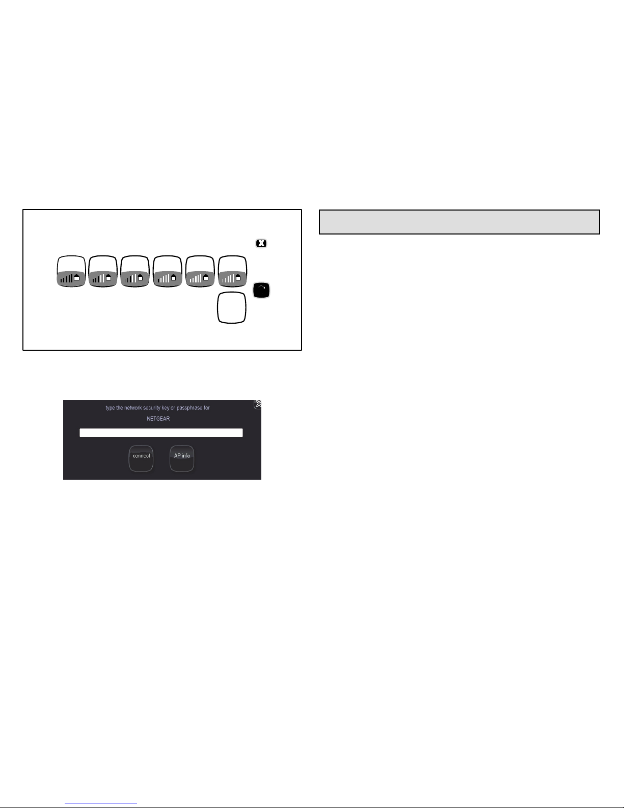
5. Touch the applicable network icon for your home Wi-Fi network.
Page 6
6
choose a wireless network
add
new
network
NETWKB NETWKC NETWKD *NETGEAR
* Selecting one of these wireless networks may result in an unreliable connection to
your thermostat. Press help for tips on improving signal strength.
NETWKE * NETWKF *
NETWORK SETTINGS
6. Touch the password field (if secure network)
7. Type in the password (if secure network) using the pop-up online
keyboard by touching screen at blank line.
8. Touch save (if secure network).
9. Touch connect.
10. The Network Settings screen will appear. If connection is successful,
the selected the access point will show connected.
If connection was not successful, use the troubleshooting tips in the next
section.
Troubleshooting Wi-Fi
ROUTER / MODEM CHECK IF CONNECTION FAILS
1. Make sure the router and modem are turned on.
2. Check for connections to other wireless devices and internet
connection.
3. Make sure the Comfort Sync thermostat's Wi-Fi is enabled and
connected to the home network (AP).
4. If having difficulty connecting to the router, online research the router
model number and/or internet provider to discover and verify that the
router band is set to B, G or N bands. You will need to access the
routers utility program to make any changes. If not accessible please
contact your service provider for help. The thermostat will connect to
B, G or N band routers at this time. NOTE: When set to B or G bands,
video streaming will likely be slower that N band. If homeowner has
implemented a dedicated N band router for the purpose of video
streaming, a separate router for the thermostat may be required.
5. Reboot your router
A Unplug your power cord, wait 30 seconds, then reconnect. If you
have multiple routers, try rebooting all of them when problems
occur.
B If their are multiple routers you must have different name and
password for each one.
C On your computer, turning Wi-Fi off and then back on will force
the system to rescan for available networks. Do you see the
network your thermostat is trying to connect to?
6. Power cycle the thermostat.
7. Keep cordless phones, microwaves and other electrical equipment at
least 3.5 feet (1m) away from access point.
A Try moving your router closer to the device if possible. If
connection is improved, then there is probably some
interference. Must have signal stronger than -70db (also, see
Router Signal Strength on page 3); anything less will have signal
losses or not connect at all.
B Adjust the direction of the router toward the thermostat. Adjust
the routers antenna. A signal repeater may be needed.
Page 7
Comfort Sync 7-Day Programmable Communicating Thermostat
7
8. Try changing channels on the access point and test it out with one of
your internet devices (i.e. laptop, desktop). The IP address to the
server from the thermostat will be close to the same IP address from
the computer to the server (www.mycomfortsync.com).
COMPUTER CONNECTIONS:
1. On Access Point, Login to configuration (usually web based interface)
→ go to Wireless Settings select a different channel → Save settings.
2. Devices cannot change Wi-Fi channel. It is set only at the router.
3. On the thermostat, disable, then re-enable the Wi-Fi connection.
4. Antenna in thermostat is fixed and cannot be moved. Location of your
access point with respect to the thermostat is very important.
5. Baby monitors, garage door openers and wireless video cameras may
create signal interference.
6. Check your encryption key (Password).
7. Double check and re-enter your WEP/WPA encryption keys /
pass-phrases (usually found on the router). If set to WEP security,
change to WPA if allowed.
8. In your thermostat's wireless settings, verify that your encryption key
(password) is correct. There can not be spaces at the end of the SSID
or Password.
9. It is important to note that number of walls that the signal must pass
thru to reach the thermostat can be an issue. (e.g. 4 indoor walls, or
1 outdoor wall + 2 indoor walls could mean a weak signal at the
thermostat).
10. The addition of a signal repeater or extender maybe an option.
(desktop or wall outlet plug-in devices are available online or at your
local electronics stores in price range $70 - $150).
11. If multiple routers are in the home make sure each router has a different
name.
12. If you don't get the pop up box that says the registration request has
been forwarded, then the email was not sent to the server and the
return registration link will not be sent to your email address. Try all the
router troubleshooting procedures and if you still can't get it to send the
email, cycle the power to the thermostat. This will cause the thermostat
to ask for the Allied server mac address again and try to resend the
email.
13. If all is correct, refer user to their Router manufacturer and Network
provider. Router may have incoming fire wall check with service
provider.
ROUTER SIGNAL STRENGTH
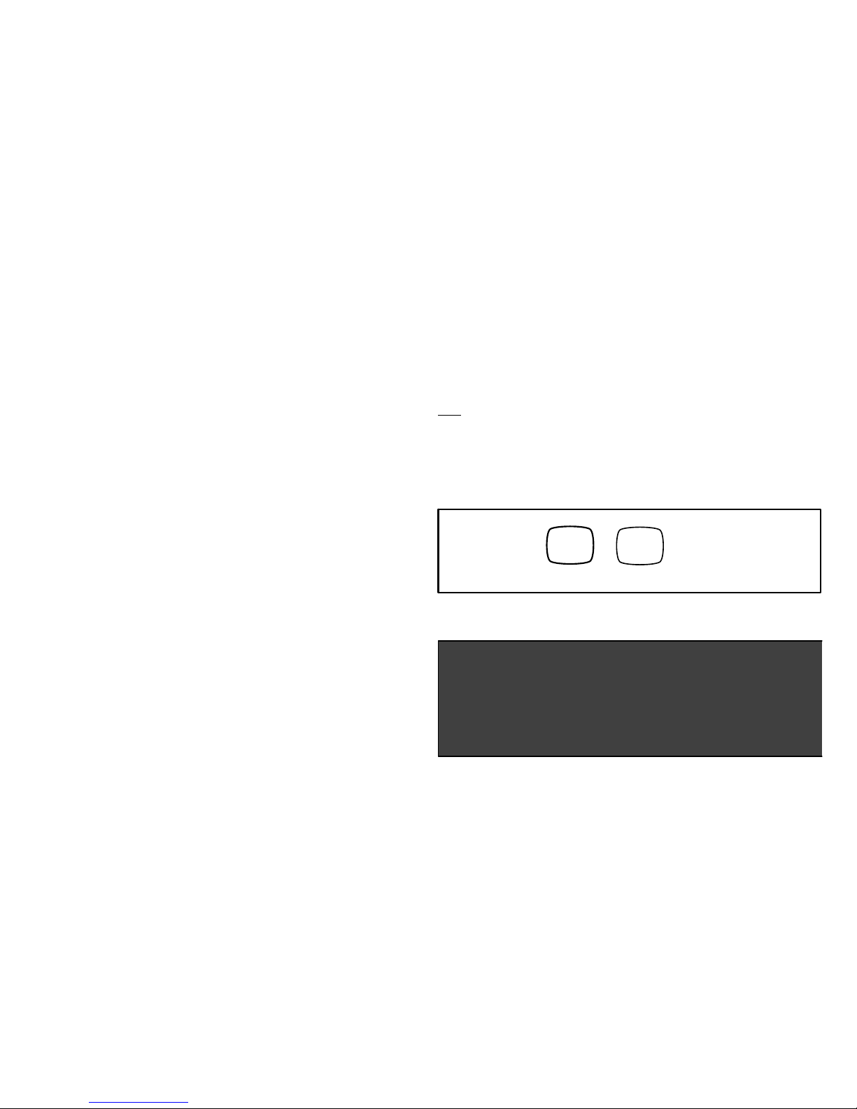
After connecting to your router, you can check your signal strength by
pushing the Wi-Fi icon on the home screen, then the networks button, then
your network button, then the AP info button (see figure 2).
A strong wireless signal (RSSI) is indicated by a NEGATIVE decibel number
in the range from -46 to -58db; anything greater than -80db will not connect.
If you are connected but have a signal above -70db then you may consider
adding a signal repeater/extender or making some of the other router
adjustment mentioned in the Router / Modem Check section
AP Info
connect
Push AP info
button
Figure 2. Access connection data
AT+NSTAT=?
MAC=00:ID:C9:A0:40:95
WSTATE=CONNECTED MODE=AP
BSSID=98:FC:11:47:B9:00 SSID= LINKSYS” CHANNEL=6 SECURITY=NONE
RSSI=-78
IP ADDR=192.168.8.117 SUBNET=255.255.255.0 GATEWAY=192.168.8.1
DNSI=192.168.1.1 DNS2=0.0.0.0
RXCOUNT=14 TXCOUNT=345
OK
Figure 3. Connection data
Page 8
8
Thermostat Registration with Allied Server
(Homeowner's router and Internet Service Provider [ISP] to the Allied
Server). This connection is used when registering your thermostat.
(Connection is up or down and there is no strength indicator for this).
When there is not a good internet connection from the router to the internet,
the thermostat will not register. You will only known this if you input your
e-mail address and system description and touch on the register button and
see the thermostat “clocking” and the registration request pop up box is not
show.
If the the registration request pop-up box is shown then you should
receive an email back from the server to your email address directing
you to the consumer portal to make an account on the Allied server. If
you don't see it in your inbox make sure you check you Junk and Spam mail
boxes.
If you don't get the pop-up box that says the registration request has been
forwarded then the email was not sent to the server and the return
registration link will not be sent to your email address. Try all the router
troubleshooting procedures and if you still can't get it to send the email, cycle
the power to the thermostat. This will cause the thermostat to ask for the
Allied server mac address again and try to resend the email. If multiple
routers are in the home make sure each router has a different name.
iPhone® app, iPad® app, and Android™ app can be downloaded from the
App Store or Android™ Play Store.
1. Touch Wi-Fi.
2. Touch Thermostat not registered.
3. Type in homeowner's email twice (this ensure the email is typed
correctly); enter System Desc.
4. Touch register.
5. Message appears while (see figure 4).
Registration request has been forwarded.
Please check your email for instructions to complete registraiton.
If you do not receive an email, please ensure you entered your
email address accurately and/or check your spam folder.
Figure 4. Screen Message after Thermostat Registration is
Completed
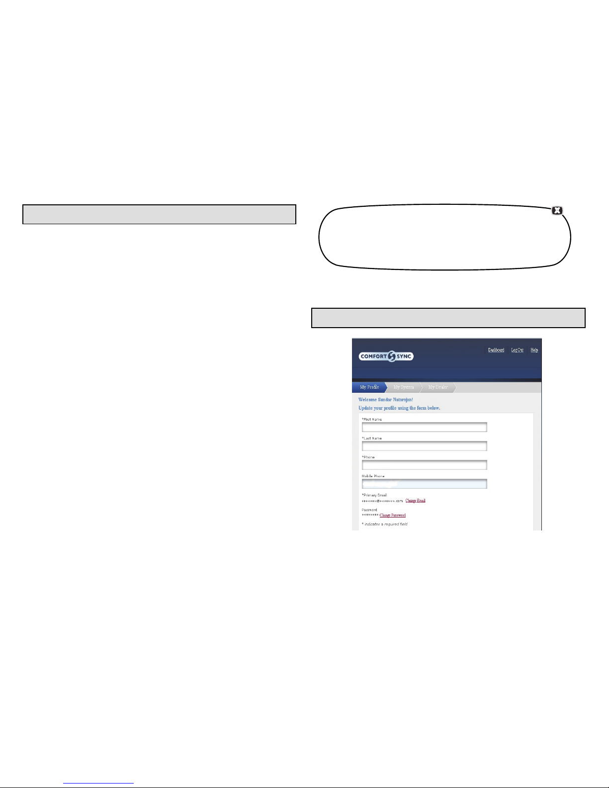
User Account Registration for Allied Server Access
Figure 5. Registration Screen
Page 9
Comfort Sync 7-Day Programmable Communicating Thermostat
9
NOTE - This following information is customer setup instructions and
is shown here to allow the installer to help walk the customer through
the setup process.
After registering through your Comfort Sync thermostat interface, go to
the homeowner's computer and locate the email sent from the server.
NOTE - if the customer has already setup an account, click the “Click
Here” button to access that account.
Click on the Register link; the screen (to the left) will appear. Fill in the User
Name and Password fields and check the agree to terms and conditions box.
Click Create User button.
A series of pages and prompts follows to provide guidance through profile
setup and user preference definitions.
Firmware Update
FIRMWARE UPDATE BUTTON
1. Firmware Update (Off) – No automatic firmware updates.
2. If the status is changed from Off to Auto, it will trigger an immediate
check and update for the firmware update. This can take up to 1 hour
to complete depending on the user's internet speed, signal strength,
internet traffic, etc.
3. Changing from Auto to Off during a download will NOT stop the current
download if it is already in process.
4. Firmware Update (Auto) – (Default state). If enabled, the thermostat
checks for firmware update a few minutes after commissioning and
then every 24 hours in early morning hours.
5. Once a download is completed, the thermostat stops all activity for up
to 3 seconds, restarts for 5 seconds, then continues with normal
operation. All prior system and user settings are retained (Equipment,
programs, Wi-Fi settings, etc.). Note a variation in indoor temperature
may be observed after restart. This is normal operation of the
thermostat while the temperature sensor algorithms adjust after a
restart of the system.
Adding Non-Communicating Outdoor Unit and Accessories
OUTDOOR UNIT (AIR CONDITIONER OR HEAT PUMP)
To add (or remove) an outdoor unit that is not Comfort Sync-enabled, you
must be at the “Add or Remove Non-communicating equipment?” screen.
1. Touch the yes button next to Add or Remove
Non-communicating equipment?.
2. In the “non-communicating device list” screen, use the arrows to
highlight Outdoor Unit Type and touch edit.
3. Touch one of the radio buttons to select a 1-or 2-stage air
conditioner unit or a 1-or 2-stage heat pump unit; touch save.
4. Use arrows to highlight any red colored text in the device list (e.g.
select Outdoor Unit Capacity; text turns white). Touch edit.
5. Use either the up or down arrows to display the correct size outdoor
unit. Touch save to continue.
NOTE - If the defaults are correct, you do not have to make any changes, but
you must touch save. When all red text is gone, the back button will appear;
touch it to return to the “Add or Remove Non-communicating equipment?”
screen.
ADDING A HUMIDIFIER
Before adding a humidifier, be sure that the:
Humidifier is wired to the furnace or air handler control as shown in the
included quick start guide.
Entire system is wired, powered up, and the thermostat has detected
the system's installed communicating devices, and you are at the “Add
or Remove Non-communicating equipment?” screen.
To add (or remove) a humidifier:
1. Touch the yes button on this screen.
2. In the “non-communicating device list” screen, use the arrows to
highlight Humidifier (note the current value, Not Installed) and touch
edit.
3. Touch one of the radio buttons to select the Bypass (24VAC)
Humidifier (or select Not Installed, if removing humidifier); touch
save.
Page 10

10
4. The previous screen returns, but the current value now shows your
selection. Touch the back button.
5. The “Add or Remove...” screen reappears with your addition shown in
the system devices list. At this point, you may add more equipment
(touch yes) or if finished, touch the next button to advance to the
“Adjust a setting...” screen.
NOTE - Adding humidity regulating non-communicating devices may be a
2-step procedure:
First the device must be installed and wired. After the humidifier is
installed, the setting under the "System" mode "Humidification Control
Mode" defaults to "Basic".
Second, if you want another mode, i.e. Precision, Basic Dew Point,
or Precision Dew Point, the device requires further configuration.
ADDING AUXILIARY DEHUMIDIFIER
Before adding a dehumidifier, be sure that:
the dehumidifier is wired to the furnace or air handler control as shown
on the optional accessories wiring diagram located in the provided
quick start guide.
the entire system is wired, powered up, and the thermostat has
detected the system's installed communicating devices, and you are
at the “Add or Remove Non-communicating equipment?” screen.
To add (or remove) a dehumidifier, you must be at the “Add or Remove
Non-communicating equipment?” screen.
1. Touch the yes button on this screen.
2. In the “non-communicating device list” screen, use the arrows to
highlight Dehumidifier and touch edit. Note the current value (e.g. Not
Installed).
3. Touch one of the radio buttons to select the Auxiliary Dehumidifier
(or select Not Installed, if removing dehumidifier); touch save.
NOTE - Humiditrol is not an available accessories. Do not select this option.
4. When you scroll to the dehumidifier device, (Note the current value,
e.g. Auxiliary Dehumidifier.) Click back to return to the “Add or
Remove...” screen.
5. The “Add or Remove...” screen reappears with your addition shown in
the system devices list. At this point, you may add more equipment
(touch yes) or if finished, touch the next button to advance to the
“Adjust a setting...” screen.
AUXILIARY DEHUMIDIFIER OPERATION
When this option is selected, dehumidification will be allowed under the
following conditions, provided there is NO call for humidification:
In the absence of heating or cooling calls, or
Simultaneous with blower only calls.
If the blower is required to operate while the auxiliary dehumidifier is running,
a separate wire must be installed from the auxiliary dehumidifier to the indoor
unit's G thermostat input that will energize G when the auxiliary dehumidifier
is running (see provided quick start guide)
Auxiliary dehumidification is controlled by the thermostat dehumidification
demand.
Adjusting Humidification and Dehumidification Settings
HUMIDIFICATION SETTINGS — SYSTEM DEVICES SCREEN
Pre-adjustment REQUIREMENTS:
First the device has been installed.
Second, you pressed next at the “Add or Remove...” screen.
DISPLAY, BASIC AND PRECISION—These modes allow user control of
relative humidity between 15 and 45%. These conditions must be met for
either mode to operate:
humidification mode has been enabled, and
the unit is in HEAT mode, and
humidification demand exists (24V present at H), and
DISPLAY mode indicates humidification is OFF.
BASIC mode mode also requires presence of heating demand [Y for
HP heat, or W for gas heat (W may be energized with G de-energized)].
PRECISION—(Available only if Wi-Fi is operational or outdoor sensor
is attached)
Page 11
Comfort Sync 7-Day Programmable Communicating Thermostat
11
Basic Dew Point Control adjustment mode will change the humidification
setpoint based on the outdoor temperature and a user-defined dew point
adjustment setting.
Precision Dew Point Control adjustment mode will operate when these
conditions are met:
humidification mode has been enabled, and
the unit is in HEAT mode, and
humidification demand exists (24V present at H).
Configure the device as follows:
1. In the “system devices” list, use the arrows to highlight System. Touch
edit.
2. In the “System” list, use the arrows to highlight Humidification
Control Mode. Touch edit.
3. Touch one of the radio buttons to select the mode of humidification
control; touch save. (After saving, check that the current value now
shows the new selection).
4. Touch the back button to return to “Adjust a setting...” screen.
NOTE - If the defaults for the settings are shown in red, you are not required
to make any changes, but you must go into the edit tool, and touch save.
When all red text is gone, the back button will appear; touch it to return to the
“Adjust a setting...” screen.
HUMIDIFICATION SETTINGS — FEATURE SCREEN
1. From the Main Screen, touch the right arrow icon to go the the
Features screen.
2. From the Features screen, select system settings.
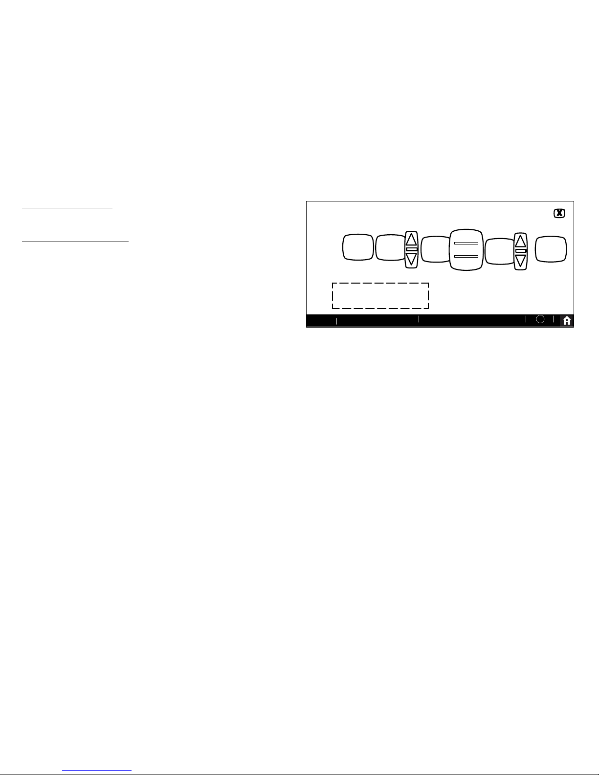
3. Touch the button for the humidification settings you want to adjust; if
it says humidifier OFF, one touch will display a selection for ON.
4. When you touch the set-to button, the arrows appear, allowing you to
change to the desired humidity percentage setting.
SYSTEM SETTINGS
current indoor humidity is 50%
humidifier
is ON
de-
humidifier
MEDIUM
40
%
set to
50
%
set to
ALL CHANGES MADE ON
THIS SCREEN ARE IN
STANTLY SAVED.
9:39 am Aug 15, 2012
?
Wi-Fi
OFF
MEDIUM
HIGH
humidity
display
is ON
humidification
settings
dehumidification
settings
Figure 6. Humidification Setting
DEHUMIDIFICATION SETTINGS — SYSTEM DEVICES SCREEN
Pre-adjustment REQUIREMENTS
First the device has been installed
Second, from the “Add or Remove Non-communicating equipment?”,
touch next.
Third, in the “Adjust a setting...” screen, configure the device as
follows:
1. In the “system devices” list, use the arrows to highlight System. Touch
edit.
2. Use arrows to highlight Min Dehumidification Setpoint; touch edit.
Note the current value (e.g. 40).
3. Use arrows to make changes; touch (After saving, check that the
current value now shows the new selection).
4. Touch the back button to return to “Adjust a setting...” screen.
DEHUMIDIFICATION SETTINGS — FEATURE SCREEN
1. From the Main Screen, touch the right arrow icon to go the the
Features screen.
2. From the Features screen, select system settings.
3. Touch the button of the dehumidification settings you want to adjust;
if it says de-humidifier OFF, one touch will display a selection for OFF,
MEDIUM or HIGH.
Page 12
12
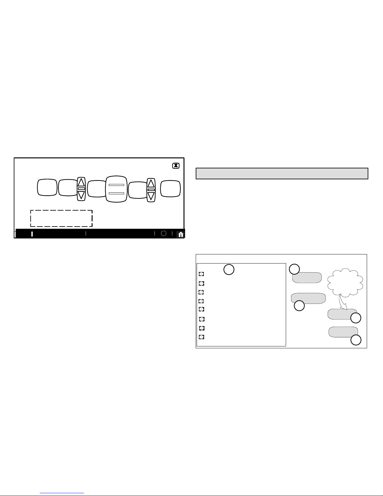
4. Selecting MEDIUM or HIGH will bring on the set-to button.
5. When you touch the set-to button, the arrows appear, allowing you to
change to the desired de-humidifier percentage setting.
SYSTEM SETTINGS
current indoor humidity is 50%
humidifier
is ON
de-
humidifier
MEDIUM
40
%
set to
50
%
set to
ALL CHANGES MADE ON
THIS SCREEN ARE IN
STANTLY SAVED.
9:39 am Aug 15, 2012
?
Wi-Fi
OFF
MEDIUM
HIGH
humidity
display
is ON
(default is ON)
humidification
settings
dehumidification
settings
Figure 7. Humidifier Controls
HOW DEHUMIDIFICATION MODE WORK — NO EXTERNAL
DEHUMIDIFICATION DEVICE
NOTE - OFF, MEDIUM and HIGH dehumidification modes are also a function of
the HVAC system with NO external dehumidification devices installed.
In OFF mode, dehumidification if off.
In MEDIUM mode, dehumidification occurs if these conditions are met and
signals are present at specific terminals:
dehumidification has been enabled on installer settings, and
the unit is in COOL mode, and
dehumidification demand exists (RH above setpoint), and
cooling demand exists (Y1 energized).
In HIGH mode, dehumidification occurs if all BASIC conditions are true, except
cooling demand may or may not be present. Also note that:
Maximum overcool from cooling setpoint is 2ºF.
Deadband temperature is limited to a minimum of 5ºF (instead of 3ºF
in DRY or MODERATE modes) because of 2ºF overcooling.
Using the Tests / Diagnostics Features
TO SELECT TESTS TO RUN
Use the following procedure to run test for various heating and cooling stage
operations.
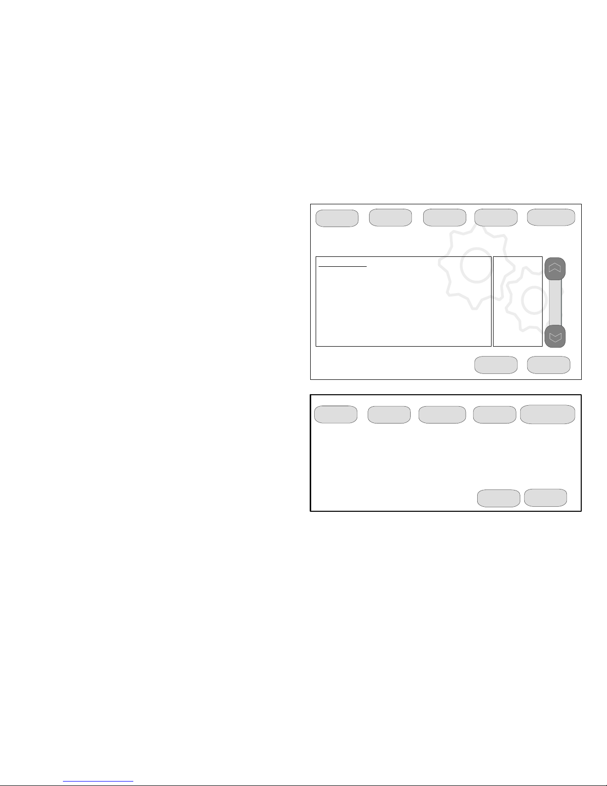
1. Select a specific tests (1) to run or use the select all (2) button to run
all configurations. Use the deselect all (3) button to un-check desired
test.
2. Touch the start button (4) to run all selected tests or touch skip tests
(5) to end the test procedure.
3. After the tests are completed or you have selected skip test select the
exit button to end.
Blower
HP Heat - 1st Stage
HP Heat - 2nd Stage
Defrost Now
Cooling - 1st Stage
Cooling - 2nd Stage
Gas Heat - 1st Stage
Gas Heat - 2nd Stage
select all
select test to run
deselect all
skip tests
start
Only appears
if test item is
selected
Ö
1
2
3
4
5
Figure 8. Selecting Tests
Page 13
Comfort Sync 7-Day Programmable Communicating Thermostat
13
NOTE - Test mode lasts for 30 minutes (with the temperature updating every
30 seconds) except for the defrost test, which lasts 30 seconds. Tests
feature provides the technician time to manually verify the equipment
operation.
The tests feature is available after setup has been completed once. After
you touch next in the final setup screen, the “select tests to run” screen
(figure 8) will appear. (If you want you may skip tests; touch skip tests.)
To run all of the tests, touch select all. All boxes in the list of tests will be
checked. Or, touch box(es) next to test(s) to run certain tests.
After the tests have been started, the screen will describe which test is
running and shows a diagnostic summary of each test (see figure 9). After
reviewing the results and concluding that no further tests are needed, touch
next to proceed to next test. The technician must verify that the test
procedure is producing the desired result at the equipment.
After pressing next after the final test, the Testing finished screen will
appear (figure 10). At this point, use the EXIT button (if you have completed
the required setup), or use diagnostics button (to analyze the system), or
use equipment button (if you wish to make any changes to device details).
9:39 am Aug 15, 2012
Heating Rate
Blower CFM Demand
Blower Off Delay
Blower On Delay
Indoor Blower RPM
Indoor Blower Power
Flame Current
Flame Sense
Outdoor Temperature
current test: Blower
Check Blower Operation
%
1400CFM
Off
Off
0
0.0000%
0.000mA
No Flame
63ºF
nextcancel
setup
tests equipment alerts diagnostics
Figure 9. Typical Tests Results Screens
9:39 am Aug 15, 2012
next
cancel
setup
tests equipment
alerts
diagnostics
press 'EXIT' button to start normal operation
The Testing Process is finished
press 'tests' button to run more tests
Figure 10. Testing Finished Screen
Page 14
14
Touch confirm to continue system configuration; the screen will change to
the system discovery screen. At this point, the program goes through the
same setup as the initial setup process which begins on page 3.
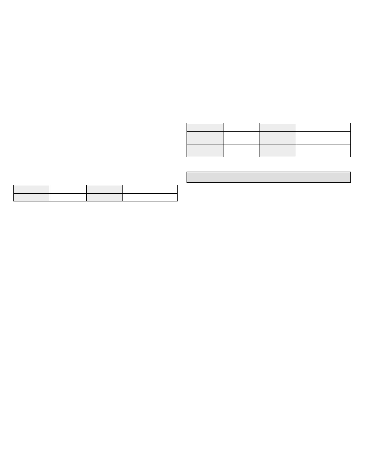
NOTE - “Compatible device found” screen (shown below) appears only
when a device has been removed and replaced with a compatible device.
Missing
Device Equipment Type No.
Model No. (control model no.)
Serial No. (control serial no.)
Found Compatible
Device Equipment Type No.
Model No. (control model no.)
Serial No. (control serial no.)
Settings were not copied
HOMEOWNER SERVICE ALERT CODES
Number Value Number Value
3000 Filter 1 3002 Humidifier Pad
3001 Filter 2 3003 UV Light
3004 Maintenance 4000 User Wi-Fi state change,
disable
4001 Firmware down
load failed
4002 Image file download failed
Alert Codes
The following tables list all alert codes used for troubleshooting system
components.
Table 1. Alert Codes and Troubleshooting
Critical alerts are displayed on Home (user) screen, in the Homeowner alert button, and in
the Installer alert button. Minor and Moderate alerts are found only in the Installer alert
button.
Alert
Code
Priority Alert Text Steps to clear
10 Critical
(Thermostat) The thermostat has found an
unknown device on the system.
An unknown device is seen on the subnet in or outside of configuration mode. Clear by
reconfiguring the system. Touch the setup tab, touch start, and touch confirm. If problem
persists, then check all DEVICE connections to make sure they are Comfort Synccom
patible.
11 Critical
(Thermostat) The thermostat cannot find a
previously installed unit.
Check all connections and cycle system power. If problem persists, clear by reconfiguring
the system. Press the setup tab, touch start, and touch confirm. If problem persists, then
check all DEVICE connections to make sure they are Comfort Synccompatible.
12 Critical
(Thermostat) The thermostat cannot find an
Comfort Syncenabled indoor unit.
Thermostat did not find an Indoor Unit. Make sure there is an Comfort Sync indoor unit
on the system. Check R, i+, i and C connections, ohm wires and cycle power. Replace
indoor unit control board if there is no response.
14 Critical
(Thermostat) The thermostat found more
than one thermostat, more than one indoor
unit, or more than one outdoor unit on the
system.
Check wiring and remove duplicate equipment. Reconfigure system.
18 Minor
(Thermostat) The outside temperature is be
low the level where the heat pump is pro
grammed to heat the home. The system will
not use the heat pump to warm your home.
Notification only Outdoor Temp is below the Low Balance Point. Heat Pump will not be
used to service a heating demand.
Page 15

Comfort Sync 7-Day Programmable Communicating Thermostat
15
Table 1. Alert Codes and Troubleshooting
Critical alerts are displayed on Home (user) screen, in the Homeowner alert button, and in
the Installer alert button. Minor and Moderate alerts are found only in the Installer alert
button.
Alert
Code
Steps to clearAlert TextPriority
19 Minor
(Thermostat) The outside temperature is
higher than the level where the furnace or
electric heat is programmed to work. The
system will only use the heat pump to warm
your home.
Notification only Outdoor Temp is above the High Balance Point. Indoor Unit (furnace or
airhandler) will not be used to service a heating demand.
29 Critical
(Thermostat) The thermostat is reading an
indoor temperature that is higher than 99ºF.
The thermostat will not allow any heating op
eration to begin until it senses a temperature
lower than 99ºF.
Indoor temperature rose above 99ºF during a heating or cooling demand. Heating opera
tion is not allowed. Check to ensure that Heating Equipment is not stuck ON (reversing
valve, etc.). Check the accuracy of the thermostat temperature sensor. Select cooling
system mode to cool the indoor space.
30 Moderate
(Thermostat) The thermostat is reading an
indoor temperature that is lower than 40ºF.
The thermostat will not allow any cooling op
eration to begin until it senses a temperature
higher than 40ºF.
Indoor Temp fell below 40ºF. Cooling operation is not allowed. Check to ensure that cool
ing equipment is not stuck ON. Check accuracy of the thermostat temperature sensor.
Select heating system mode to heat the indoor space to above 40ºF.
31 Critical
(Thermostat) The thermostat has lost com
munication with the (furnace, airhandler or
outdoor unit) for more than 3 minutes.
[Indicated unit] has not communicated with thermostat for more than 3 minutes. Check
connections. Ohm wires. If fault persists, then cycle power. Fault clears after communica
tion is restored.
32 Moderate
(Thermostat) The (furnace, airhandler or
outdoor unit) is resetting itself.
[Indicated unit] is resetting itself. This event may occur during a power outage or power
fluctuation in the system. If persistent or if it coincides with the system operation then
proceed with the following steps. Check the power connections, check the amp draw at
the transformer (the transformer maybe overloaded) and check 24VAC voltage at the
DEVICE. The alarm is only cleared by pressing the clear button on the Installer Alerts Tab.
If the fault persists after checking the connections, replace the unit's control board.
34 Critical
(Thermostat) The thermostat does not know
the capacity (tonnage) of the (furnace,
airhandler or outdoor unit). Please program
the correct capacity of the (furnace,
airhandler or outdoor unit).
[Indicated unit] is missing the programmed unit capacity. Go to [Indicated unit] and pro
gram the unit capacity manually. See the unit IOM for programming instructions. Remove
power to thermostat before programming the unit control board. Once programming is
complete, reconnect thermostat wires and reconfigure system.
Page 16

16
Table 1. Alert Codes and Troubleshooting
Critical alerts are displayed on Home (user) screen, in the Homeowner alert button, and in
the Installer alert button. Minor and Moderate alerts are found only in the Installer alert
button.
Alert
Code
Steps to clearAlert TextPriority
36 Critical
(Thermostat) The system has been heating
for at least 15 minutes, without a demand for
heating.
Run the system in diagnostic mode and verify that it matches actual equipment operation.
Check for other alarms/codes that may be preventing the system from operating as ex
pected.
Step 1: Check all heating equipment to determine cause of heating demand.
Step 2: Recycle power.
System will clear code when it detects condition has cleared.
37 Critical
(Thermostat) The system has been cooling
for at least 15 minutes, without a demand for
cooling.
Run the system in diagnostic mode and verify that it matches actual equipment operation.
Check for other alarms/codes that may be preventing the system from operating as ex
pected.
Step 1: Check all cooling equipment to determine cause of cooling demand.
Step 2: Recycle power.
System will clear code when it detects condition has cleared.
38 Critical
(Thermostat) The system has not been able
to turn on the heating for more than 45
minutes. The system will go offline for 60
minutes and try again.
Run the system in diagnostic mode and verify that it matches actual equipment operation.
Check for other alarms/codes that may be preventing the system from operating as ex
pected.
Step 1: Check all heating equipment to determine cause.
Step 2: Recycle power.
System will clear code when it detects condition has cleared.
39 Critical
(Thermostat) The system has not been able
to turn on the cooling for more than 45
minutes. The system will go offline for 60
minutes and try again.
Run the system in diagnostic mode and verify that it matches actual equipment operation.
Check for other alarms/codes that may be preventing the system from operating as ex
pected.
Step 1: Check all cooling equipment to determine cause.
Step 2: Recycle power.
System will clear code when it detects condition has cleared.
105 Critical
(Thermostat / Furnace / Air Handler / Out
door Unit) The (Thermostat, furnace,
airhandler or outdoor unit) has lost commu
nication with the rest of the system.
Equipment is unable to communicate. This may indicate the existence of other alarms/
codes. In most cases errors are related to electrical noise. Make sure high voltage power
is separated from RSBus. Check for incorrectly wired and/or loose connections between
the Thermostat, indoor unit and outdoor unit. Check for a high voltage source of noise
close to the system. Generally, this is a selfrecoverable error.
110 Critical (Furnace) The line voltage is too low.
This alarm/code may appear during a brownout. Line voltage is below its designed operat
ing value. Check and correct the power line voltage.
Page 17

Comfort Sync 7-Day Programmable Communicating Thermostat
17
Table 1. Alert Codes and Troubleshooting
Critical alerts are displayed on Home (user) screen, in the Homeowner alert button, and in
the Installer alert button. Minor and Moderate alerts are found only in the Installer alert
button.
Alert
Code
Steps to clearAlert TextPriority
111 Critical
(Furnace) The line power voltage wiring is
reversed.
The unit is reporting that its power line and neutral are reversed. Turn off the power to the
system and correct the line power voltage wiring. System resumes normal operation 5
seconds after fault recovered.
112 Critical
(Furnace) The reporting device cannot find
earth ground. The thermostat will shut down
the system.
Provide proper earth ground to the equipment. System resumes normal operation 5
seconds after fault recovered.
113 Critical (Furnace) The line voltage is too high.
Line voltage high (voltage higher than nameplate rating). Provide power voltage within
proper range. System resumes normal operation 5 seconds after fault recovered.
114 Critical
(Furnace / Air Handler) There is a fre
quency/distortion problem with the power to
the (furnace or airhandler).
This alarm/code may indicate transformer overloading. Check the voltage and line power
frequency. Check the generator operating frequency, if the system is running on backup
power. Correct voltage and frequency problems. System resumes normal operation 5
seconds after fault recovered.
115 Critical
(Furnace / Air Handler) The 24VAC to the
(furnace or airhandler control board) is
lower than the required range of 18 to
30VAC.
24Volt Power Low (Range is 18 to 30 volts). Check and correct voltage. Check for addi
tional powerrobbing equipment connected to system. This alarm/code may require the
installation of an additional or larger VA transformer.
117 Minor
(Furnace) The reporting unit has poor earth
grounding.
Provide proper grounding for the unit. Check for proper earth ground to the system. The
alarm/code will clear 30 seconds after it is corrected.
120 Moderate
(Thermostat / Furnace / Air Handler / Out
door Unit) There is a delay in the (Thermo
stat, furnace, airhandler or outdoor unit) re
sponding to the system.
Typically, this alarm/code does not cause any issues and will clear on its own. The alarm/
code is usually caused by a delay in the outdoor unit responding to the thermostat. Check
all wiring connections. Cleared after unresponsive device responds to any inquiry.
124 Critical
(Thermostat / Furnace / Air Handler / Out
door Unit) The thermostat has lost commu
nication with the (furnace, airhandler or out
door unit) for more than 3 minutes.
Equipment lost communication with the thermostat. Check the wiring connections, ohm
wires and cycle power. The alarm stops all associated HVAC operations and waits for a
heartbeat message from the unit that's not communicating. The alarm/fault clears after
communication is reestablished.
125 Critical
(Thermostat / Furnace / Outdoor Unit) There
is a hardware problem on either the (Ther
mostat, furnace control board, airhandler
control board or outdoor unit control board).
There is a control hardware problem. Replace the control if the problem prevents opera
tion and is persistent. The alarm/fault is cleared 300 seconds after the fault recovers.
126 Critical
(Furnace / Outdoor Unit) There is an internal
communication problem with the (furnace
control board, airhandler control board or
outdoor unit control board).
There is an internal hardware problem on the control. Typically the control will reset itself.
Replace the control if the problem prevents operation and is persistent. The alarm/fault is
cleared 300 seconds after the fault recovers.
Page 18

18
Table 1. Alert Codes and Troubleshooting
Critical alerts are displayed on Home (user) screen, in the Homeowner alert button, and in
the Installer alert button. Minor and Moderate alerts are found only in the Installer alert
button.
Alert
Code
Steps to clearAlert TextPriority
130 Moderate
(Air Handler) An airhandler configuration
jumper is missing.
Configuration jumper(s) missing on control (applicable in noncommunicating applications
only). Replace the jumper or put wire between terminals on control. Cleared after jumper is
connected.
131 Critical
The (Thermostat, furnace, airhandler or out
door unit) control parameters are corrupted.
Reconfigure the system. Replace the control if heating or cooling is not available.
132 Critical
(Air Handler) The device's control software
is corrupted.
Recycle power. If failure reoccurs, replace the control. System reset is required to recov
er.
180 Critical
(Furnace / Air Handler / Outdoor Unit) The
thermostat has found a problem with the
(furnace, airhandler or outdoor unit) outdoor
sensor.
In normal operation after control recognizes sensors, the alarm will be sent if valid temper
ature reading is lost. Compare outdoor sensor resistance to temperature/resistance charts
in unit installation instructions. Replace sensor pack if necessary. At the beginning of (any)
configuration, furnace or airhandler control will detect the presence of the sensor(s). If
detected (reading in range), appropriate feature will be set as 'installed' and shown in the
'About' screen. The alarm/fault will clear upon configuration, or sensing normal values.
200 Critical
(Furnace) The furnace roll out limit switch is
open.
Correct the cause of roll out trip. Reset roll out switch. Reset power to clear. Test the fur
nace operation. The alarm/fault clears after the furnace roll out switch is closed.
201 Critical
(Furnace / Air Handler) The system has lost
communication with the (furnace or airhand
ler) indoor blower motor.
Lost communication with indoor blower motor. Possible causes include: power outage,
brownout, motor not powered, loose wiring, condensation on air handler control without
cover on breaker. Problem may be on control or motor side. Cleared after communication
is restored.
202 Critical
(Furnace / Air Handler) The unit size code
for the (furnace or airhandler) and the size
of blower motor do not match.
Incorrect appliance unit size code selected. Check for proper configuring under Unit Size
Codes for Furnace/Air Handler on configuration guide or in installation instructions. The
alarm/fault clears after the correct match is detected following a reset. Remove the ther
mostat from the system while applying power and reprogramming.
203 Critical
(Furnace / Air Handler) The unit size code
for the (furnace or airhandler) has not been
selected.
No appliance unit size code selected. Check for proper configuring under: Unit Size Codes
for Furnace/Air Handler on configuration guide or in installation instructions. Critical Alert.
The alarm/fault clears after the correct match is detected following a reset. Remove the
thermostat from the system while applying power and reprogramming.
204 Critical
(Furnace) There is a problem with the fur
nace gas valve.
Check gas valve operation and wiring. The alarm/fault clears after the issue is corrected.
205 Critical
(Furnace) The furnace gas valve relay con
tact is closed.
Check wiring on control and gas valve. The alarm/fault clears after the issue is corrected.
206 Critical
(Furnace) The furnace gas valve 2nd stage
relay is faulty.
Furnace will operate on 1st stage for the remainder of the heating demand. The alarm/fault
will clear after the issue is corrected. If unable to operate 2nd stage, replace control.
Page 19

Comfort Sync 7-Day Programmable Communicating Thermostat
19
Table 1. Alert Codes and Troubleshooting
Critical alerts are displayed on Home (user) screen, in the Homeowner alert button, and in
the Installer alert button. Minor and Moderate alerts are found only in the Installer alert
button.
Alert
Code
Steps to clearAlert TextPriority
207 Critical
(Furnace) The furnace hot surface igniter is
open.
Measure the resistance of hot surface igniter. Replace the it if it is not within the specified
range found in IOM. The alarm/fault clears after the issue is corrected.
223 Critical
(Furnace) The furnace low pressure switch
is open.
Check pressure (inches w.c.) of low pressure switch closing during a heat call. Measure
operating pressure (inches w.c.). Inspect vent and combustion air inducer for correct
operation and restriction. The alarm/fault clears after the issue is corrected.
224 Critical
(Furnace) The furnace low pressure switch
is stuck closed.
Check operation of low pressure switch to see if it is stuck closed for longer than 150
seconds during a heat call . Measure operating pressure (inches w.c.). Inspect vent and
combustion air inducer for correct operation and restriction. The alarm/fault clears after the
issue is corrected.
225 Critical
(Furnace) The furnace high pressure switch
is failing to close.
Check pressure (inches w.c.) of high pressure switch closing during a heat call. Measure
operating pressure (inches w.c.). Inspect vent and combustion air inducer for correct
operation and restriction. The alarm/fault clears after the issue is corrected.
226 Critical
(Furnace) The furnace high pressure switch
is stuck closed.
Check operation of high pressure switch closing during a heat call. Measure operating
pressure (inches w.c.). Inspect vent and combustion air inducer for correct operation and
restriction. The alarm/fault clears after the issue is corrected.
227 Moderate
(Furnace) The furnace low pressure switch
is open in run mode.
Check pressure (inches w.c.) of low pressure switch closing during a heat call. Measure
operating pressure (inches w.c.). Inspect vent and combustion air inducer for correct
operation and restriction. The alarm/fault clears after the issue is corrected.
228 Moderate
(Furnace) The furnace control is not able to
calibrate the pressure switch.
Unable to perform pressure switch calibration. Check vent system and pressure
switch wiring connections. Check the drain trap for blockage. The alarm/fault clears after a
successful calibration.
229 Minor
(Furnace) The furnace control has switched
to high fire ignition because the low fire pres
sure switch did not close in the allowed time.
IFC switched to high fire ignition because low fire pressure switch did not close in allowed
time. No action is needed.
240 Moderate (Furnace) The furnace flame current is low.
Check microamperes of the flame sensor using thermostat diagnostics. Clean or replace
the flame sensor. Measure voltage of neutral to ground to ensure good unit ground. The
alarm clears after a proper microamp reading has been sensed.
241 Critical
(Furnace) The furnace flame is going out
while the furnace is heating.
Shut off gas. Check for a gas valve leak. Replace the gas valve if needed. The alarm/fault
will clear when a heat call ends successfully.
250 Moderate
(Furnace) The furnace primary limit switch is
open.
Check for proper firing rate on furnace. Ensure there is no blockage in the furnace and the
duct work. Check for proper air flow. If limit switch is not closed within 3 minutes, the unit
will go into 1hour Watchguard mode. The alarm/fault will clear when a heat call ends
successfully.
Page 20

20
Table 1. Alert Codes and Troubleshooting
Critical alerts are displayed on Home (user) screen, in the Homeowner alert button, and in
the Installer alert button. Minor and Moderate alerts are found only in the Installer alert
button.
Alert
Code
Steps to clearAlert TextPriority
252 Moderate
(Furnace) The furnace discharge airtemper
ature is high.
Check temperature rise, air flow and input rate. Check for dirty filters. The alarm/fault will
clear when a heat call ends successfully.
270 Critical
(Furnace) The furnace is in Watchguard
mode. The furnace igniter cannot turn on the
flame.
Check for proper gas flow. Ensure that igniter is lighting burner. Check flame sensor cur
rent. Check for dirty filters. The alarm/fault will clear on successful ignition.
271 Critical
(Furnace) The furnace is in Watchguard
mode. The furnace low pressure switch is
open.
Check pressure (inches w.c.) of low pressure switch closing during a heat call. Measure
operating pressure (inches w.c.). Inspect vent and combustion air inducer for correct
operation and restriction. The alarm/fault will clear on successful ignition.
272 Critical
(Furnace) The furnace is in Watchguard
mode. The furnace low pressure switch is
open during run mode.
Check operation of low pressure switch to see if it is stuck open during a heat call. Meas
ure operating pressure (inches w.c.). Inspect vent and combustion air inducer for correct
operation and restriction. The alarm/fault will clear when a heat call ends successfully.
273 Critical
(Furnace) The furnace is in Watchguard
mode. The furnace flame is going off during
a heating cycle.
Check microamperes of flame sensor using thermostat diagnostics. Clean or replace
sensor. Measure voltage of neutral to ground to ensure good unit ground. The alarm/fault
will clear when a heat call ends successfully.
274 Critical
(Furnace) The furnace limit switch has been
open for more than 3 minutes.
The system will go into Watchguard mode. Check firing rate and air flow. Check for block
age. The alarm/fault will clear when a heat call ends successfully.
275 Critical
(Furnace) The furnace flame is out of se
quence.
The system will go into Watchguard mode. Shut off gas. Check for gas valve leak. The
alarm/fault will clear on next successful ignition.
276 Critical
(Furnace) The furnace is not able to calib
rate or the high pressure switch opened or
failed to close in run mode.
The system will go into Watchguard mode. Check vent system and pressure
switch wiring connections. The fault/alarm will clear when the furnace calibrates itself
successfully.
290 Critical
(Furnace) There is a problem with the fur
nace ignition circuit.
The system will go into Watchguard mode. Measure resistance of hot surface igniter.
Replace the hot surface ignitor it is not within specifications. The alarm/fault will clear on
next successful ignition.
291 Critical
(Furnace) The heating airflow is below the
minimum required level.
The system will go into Watchguard mode. Check for dirty filters and other air flow restric
tions. Check blower performance. The alarm/fault will clear when a heat call ends suc
cessfully.
292 Critical
(Furnace / Air Handler) The (furnace or
airhandler) indoor blower motor will not
start.
The system will go into Watchguard mode. Indoor blower motor unable to start. This could
be due to seized bearing, stuck wheel, obstruction etc. Replace motor or wheel if as
sembly does not operate or meet performance standards. The alarm/fault clears after the
indoor blower motor starts successfully.
Page 21

Comfort Sync 7-Day Programmable Communicating Thermostat
21
Table 1. Alert Codes and Troubleshooting
Critical alerts are displayed on Home (user) screen, in the Homeowner alert button, and in
the Installer alert button. Minor and Moderate alerts are found only in the Installer alert
button.
Alert
Code
Steps to clearAlert TextPriority
294 Critical
(Furnace) There is over current in the fur
nace inducer motor.
The system will go into Watchguard mode. Check combustion blower bearings, wiring and
amps. Replace if does not operate or does not meet performance standards. The alarm/
fault clears after inducer current is sensed to be inrange after the ignition following the
Watchguard mode or reset.
295 Minor
(Furnace) The indoor blower motor is over
heating.
Indoor blower motor over temperature (motor tripped on internal protector). Check motor
bearings and amps. Replace if necessary. The alarm/fault clears after blower demand is
satisfied.
310 Critical
(Furnace / Air Handler) There is a problem
with (furnace or airhandler) discharge air
sensor.
Compare outdoor sensor resistance to temperature/resistance charts in installation in
structions. Replace sensor if necessary. The alarm/fault is cleared 30 seconds after fault is
detected as recovered.
311 Minor
(Furnace) The heat firing rate has been re
duced to match available airflow (cutback
mode).
Warning Only. Furnace blower in cutback mode due to restricted airflow. Reduce firing rate
every 60 seconds to match available CFM. Check filter and duct system. To clear, replace
filter if needed or repair/add duct. 2stage controls will reduce firing rate to 1st stage. The
alarm/fault clears when a heat call finishes successfully.
312 Minor
(Furnace / Air Handler) The blower cannot
provide the requested CFM due to high stat
ic.
Warning Only. Restricted airflow Indoor blower is running at a reduced CFM (Cutback
Mode The variable speed motor has preset speed and torque limiters to protect the
motor from damage caused by operating outside of design parameters (0 to 0.8” e.g.. total
external static pressure). Check filter and duct system. To clear, replace filter if needed or
repair/add duct. The alarm/fault is cleared after the current service demand is satisfied.
313 Minor
(Furnace / Air Handler) The indoor and out
door unit capacities do not match.
Check for proper configuring in installation instructions. Alarm is just a warning. The sys
tem will operate, but might not meet efficiency and capacity parameters. The alarm will
clear after commissioning is complete.
344 Critical (Furnace) Relay Y1 Failure Y1 relay failed; operation stopped. Alarm clears 300 seconds after Y1 input sensed OFF.
345 Critical
(Air Handler / Heat Pump) The “O” relay on
the airhandler has failed. Either the pilot re
lay contacts did not close or the relay coil did
not energize.
O relay / Stage 1 failed. Pilot relay contacts did not close or the relay coil did not energize.
Replace control. Cleared after the fault recovered following reset.
346 Critical
(Air Handler) The heat pump jumper was not
removed on the airhandler control board.
Configuration link(s) not removed on control. Cut OR. Applicable with non communicating
outdoor unit with communicating indoor system.
347 Critical
(Furnace / Air Handler) The “Y1” relay on the
(furnace or airhandler) has failed. Either the
pilot relay contacts did not close or the relay
coil did not energize.
Operation stopped. Y1 relay / Stage 1 failed. (Pilot relay contacts did not close or
the relay coil did not energize; no input back to IFC chip). Critical Alert. Cleared after reset
and Y1 input sensed.
Page 22

22
Table 1. Alert Codes and Troubleshooting
Critical alerts are displayed on Home (user) screen, in the Homeowner alert button, and in
the Installer alert button. Minor and Moderate alerts are found only in the Installer alert
button.
Alert
Code
Steps to clearAlert TextPriority
348 Critical
(Furnace / Air Handler) The “Y2” relay on the
(furnace or airhandler) has failed. Either the
pilot relay contacts did not close or the relay
coil did not energize.
Y2 relay / Stage 2 failed. (Pilot relay contacts did not close or the relay coil did not ener
gize; no input back to IFC chip). Critical Alert. Cleared after reset and Y1 input sensed.
349 Critical
(Furnace) The “O” to “R” jumper on the fur
nace needs to be restored.
Configuration link R to O needs to be restored. Replace link or hardwire. Applicable in non
communicating mode. Critical Alert.
350 Critical
(Air Handler) The airhandler's electric heat
is not configured.
Heat call with no configured or incorrectly configured electric heat. Check for proper con
figuring under Configuring Electric Heat Stages in the air handler installation instructions.
Cleared after electrical heat detection is successful.
351 Critical
(Air Handler) There is a problem with the
airhandler's 1st stage electric heat. Either
the pilot relay contacts did not close, or the
relay coil in the electric heat section did not
energize.
Heat section / Stage 1 failed. (Pilot relay contacts did not close, or the relay coil in the
electric heat section did not energize.) Air handler will operate on 1st stage for reminder of
the heat call. Will clear after fault recovered.
352 Critical
(Air Handler) There is a problem with the
airhandler's 2nd stage electric heat. Either
the pilot relay contacts did not close, or the
relay coil in the electric heat section did not
energize. The airhandler will operate on 1st
stage electric heat until the issue is resolved.
Heat section / Stage 2 failed (Same as Code 351).
353 Critical
(Air Handler) There is a problem with the
airhandler's 3rd stage electric heat. Either
the pilot relay contacts did not close, or the
relay coil in the electric heat section did not
energize. The airhandler will operate on 1st
stage electric heat until the issue is re
solved.`
Heat section / Stage 3 failed (Same as Code 351).
354 Critical
(Air Handler) There is a problem with the
airhandler's 4th stage electric heat. Either
the pilot relay contacts did not close, or the
relay coil in the electric heat section did not
energize. The airhandler will operate on 1st
stage electric heat until the issue is resolved.
Heat section / Stage 4 failed (Same as Code 351).
Page 23

Comfort Sync 7-Day Programmable Communicating Thermostat
23
Table 1. Alert Codes and Troubleshooting
Critical alerts are displayed on Home (user) screen, in the Homeowner alert button, and in
the Installer alert button. Minor and Moderate alerts are found only in the Installer alert
button.
Alert
Code
Steps to clearAlert TextPriority
355 Critical
(Air Handler) There is a problem with the
airhandler's 5th stage electric heat. Either
the pilot relay contacts did not close, or the
relay coil in the electric heat section did not
energize. The airhandler will operate on 1st
stage electric heat until the issue is resolved.
Heat section / Stage 5 failed (Same as Code 351).
370 Critical
(Furnace) The furnace control has not re
ceived 24VAC power for 2 minutes or more.
Control sees the loss of 24VAC for 2 minutes .Terminate all services and wait for
interlock switch to close. The alarm will clear when 24VAC is continuously sensed on DS
terminal for a minimum of 10 seconds or on a power reset. If 2 stage with float switch, the
IFC control RDS is open.
400 Critical
(Outdoor Unit) The compressor internal
overload has tripped.
Thermostat demand Y1 is present; but, compressor is not running. Check power to unit.
Clears the error after current is sensed in both RUN and START sensors for at least 2
seconds, or after service is removed, or after power reset.
401 Moderate
(Outdoor Unit) Either the compressor ran for
more than 18 hours continuously trying to
cool the home or the refrigerant pressure in
the system is low.
Compressor ran more than 18 hours to satisfy a single thermostat demand. Will not lock
out system. If 2 stage, units with blinking LED light controls, unit will run in low speed; units
with 7segment display will display code, but continue to run in high speed. If a Heat
Pump, and if outdoor temp is less than 65 degrees, code is ignored. Clears the error after
30 consecutive normal run cycles or power reset. Also monitors low pressure switch trips.
402 Critical
(Outdoor Unit) Either the discharge or suc
tion pressure level is outoflimits, or the is
compressor overloaded.
Discharge or suction pressure outoflimits, or compressor overloaded. Clears the error
after 4 consecutive normal compressor run cycles.
403 Moderate
(Outdoor Unit) The compressor ran for less
than 3 minutes to satisfy a thermostat de
mand.
Compressor runs less than 3 minutes to satisfy a thermostat demand. Clears the error
after 4 consecutive normal run cycles or power reset.
404 Critical
(Outdoor Unit) The compressor rotor is
locked up. This could be due to a short cir
cuiting of the run capacitor, seizing of the
bearings or excessive liquid refrigerant etc.
Compressor rotor locked up due to run capacitor short, bearings are seized, excessive
liquid refrigerant, etc. (NOTE: May need to install hard start kit). Clears the error after 4
consecutive normal run cycles or after power reset.
405 Critical
(Outdoor Unit) The compressor circuit is
open. This could be due to a power discon
nection, open fuse etc.
Compressor circuit open (due to power disconnection, open fuse, etc.) Clears the error
after 1 normal compressor run cycle.
406 Critical
(Outdoor Unit) The required amount of cur
rent is not passing through the start current
transformer.
Required amount of current is not passing through Start current transformer. Clears the
error after current is sensed in START sensor, or after power reset.
Page 24

24
Table 1. Alert Codes and Troubleshooting
Critical alerts are displayed on Home (user) screen, in the Homeowner alert button, and in
the Installer alert button. Minor and Moderate alerts are found only in the Installer alert
button.
Alert
Code
Steps to clearAlert TextPriority
407 Critical
(Outdoor Unit) The required amount of cur
rent is not passing through run current trans
former.
Required amount of current is not passing through Run current transformer. Clears the
error after current is sensed in RUN sensor, or 1 normal compressor run cycle, or after
power reset
408 Critical
(Outdoor Unit) The compressor is running
continuously.
Compressor runs continuously. Clears the error after 1 normal compressor run cycle or
after power reset.
409 Moderate
(Furnace / Air Handler / Outdoor Unit) The
secondary voltage for the (furnace, airhand
ler or outdoor unit) has fallen below 18VAC.
If this continues for 10 minutes, the thermo
stat will turn off the (furnace, airhandler or
outdoor unit).
Secondary voltage is below 18VAC. After 10 minutes, operation is discontinued. Clears the
code after voltage is higher than 20 VAC for 2 seconds or after power reset.
410 Moderate
(Outdoor Unit) The outdoor unit pressure is
below the required limit.
Unit pressures are below the lower limit. Pressure switch opens at 40 psig (system shuts
down) and closes at 90 psig (system restarts).
411 Critical
(Outdoor Unit) The low pressure switch has
opened 5 times during one cooling cycle. As
a result, the thermostat has shutdown the
outdoor unit.
Open low pressure switch error count reached 5 strikes. Check system charge using
approach and sub cooling temperatures. Reset by putting outdoor unit control in test mode
or resetting low voltage power.
412 Moderate
(Outdoor Unit) The outdoor unit pressure is
above the required limit. The system will
shut down.
Unit pressure is above the upper limit. System is shut down. The high pressure switch for
HFC410A will open at 590PSIG and close at 418PSIG. Confirm that the system is prop
erly charged with refrigerant. Check condenser fan motor, TXV, indoor unit blower motor,
stuck reversing valve or clogged refrigerant filter. Confirm that the outdoor unit is clean.
The alarm clears after the pressure switch closes or a power reset
413 Critical
(Outdoor Unit) The high pressure switch has
opened 5 times during one cooling cycle. As
a result, the thermostat has shutdown the
outdoor unit.
Open high pressure switch error count reached 5 strikes. Check system charge using
approach and sub cooling temperatures. Check outdoor fan operation. Check for dirt or
debris blocking air flow to outdoor unit. Reset by putting outdoor unit control in test mode
or resetting low voltage power.
414 Critical
(Outdoor Unit) The discharge line temperat
ure is higher than the recommended upper
limit of 279ºF.
Discharge line temperature is > 279ºF. Make sure coil is clean and airflow unobstructed in
and out of condenser. Check system operating pressures and compare to unit charging
charts in installation manual. Clears after discharge temperature is < 225ºF.
415 Critical
(Outdoor Unit) The discharge line temperat
ure has been consistently higher than the
recommended upper limit of 279ºF.
Discharge line high temperature error count reached 5 strikes. Make sure coil is clean and
airflow unobstructed in and out of condenser. Check system charge using approach and
sub cooling temperatures. Reset by putting outdoor board in test mode or resetting low
voltage power.
Page 25

Comfort Sync 7-Day Programmable Communicating Thermostat
25
Table 1. Alert Codes and Troubleshooting
Critical alerts are displayed on Home (user) screen, in the Homeowner alert button, and in
the Installer alert button. Minor and Moderate alerts are found only in the Installer alert
button.
Alert
Code
Steps to clearAlert TextPriority
416 Critical
(Outdoor Unit) The outdoor coil sensor is
either open, shortcircuited or the temperat
ure is out of sensor range. As a result the
outdoor unit control will not perform any de
frost tempering.
Sensor being detected open or shorted, or temperature is out of sensor range.
Outdoor unit control will not perform demand or time/temperature defrost operation. (Sys
tem will still heat or cool.) Clears when outdoor unit control detects proper sensor read
ings.
417 Critical
(Outdoor Unit) The outdoor unit sensor is
either open, shortcircuited or the temperat
ure is out of sensor range. As a result the
outdoor unit control will not perform any de
frost tempering.
Outdoor unit control detects open or shorted sensor, or temperature that is out of sensor
range. Critical Alert after 10 minutes. Reset by replacing sensor. This fault is detected by
allowing the unit to run for 90 seconds before checking sensor resistance. If the sensor
resistance is not within range after 90 seconds, the board will count one fault. After 5
faults, the board will lock out. Check for proper sensor reading and attachment to line.
Replace if outofspecifications.
418 Moderate
(Outdoor Unit) There is a faulty “W” output
circuit.
Faulty W output circuit.
419 Critical
(Outdoor Unit) The “W” output on the out
door unit has reported more than 5 errors.
As a result, the system has shutdown the
outdoor unit.
W output hardware fault count reached 5 strikes.
420 Critical
(Outdoor Unit) The “W” output terminal on
the outdoor unit is not wired correctly
Defrost cycle lasts longer than 20 minutes. Check heat pump operation. Cleared when W1
signal is removed. Applicable only in communicating mode with noncommunicating heat
pump.
421 Critical
(Air Handler). The heat pump defrost cycle
has taken more than 20 minutes to com
plete.
Voltage sensed on W output terminal when Y1 out is deactivated.
700 Moderate
(Thermostat) The temperature sensor in the
thermostat is not working properly.
Recalibrate thermostat to clear. Replace thermostat if needed.
701 Moderate
(Thermostat) The thermostat is reading in
door temperatures above the prepro
grammed limit.
Recalibrate thermostat to clear; cool thermostat; adjust setpoint. Replace thermostat, if
needed.
702 Moderate
(Thermostat) The thermostat is reading in
door temperatures below the prepro
grammed limit.
Recalibrate thermostat to clear; warm thermostat; adjust setpoint. Replace thermostat, if
needed.
703 Moderate
(Thermostat) The humidity sensor in the
thermostat is not working properly.
Recalibrate thermostat to clear; adjust setpoint. Replace thermostat, if needed.
Page 26

26
Table 1. Alert Codes and Troubleshooting
Critical alerts are displayed on Home (user) screen, in the Homeowner alert button, and in
the Installer alert button. Minor and Moderate alerts are found only in the Installer alert
button.
Alert
Code
Steps to clearAlert TextPriority
704 Moderate
(Thermostat) The thermostat is reading in
door humidity levels above the prepro
grammed limit.
Recalibrate thermostat to clear. Replace thermostat, if needed.
705 Moderate
(Thermostat) The thermostat is reading in
door humidity levels below the prepro
grammed limit.
Recalibrate thermostat to clear. Replace thermostat, if needed.
Ohm
Check
—
The ohm reading in the system is either too
high or too low.
Ohm reading between i+ and i anywhere on the RSBus with supply power off should be
between 70 and 90 ohms. If above 90 ohms, check and repair wiring, splices or other
wiring defects that may be causing the excessive resistance. If less than 70 ohms, check
for shorted wires.
Page 27
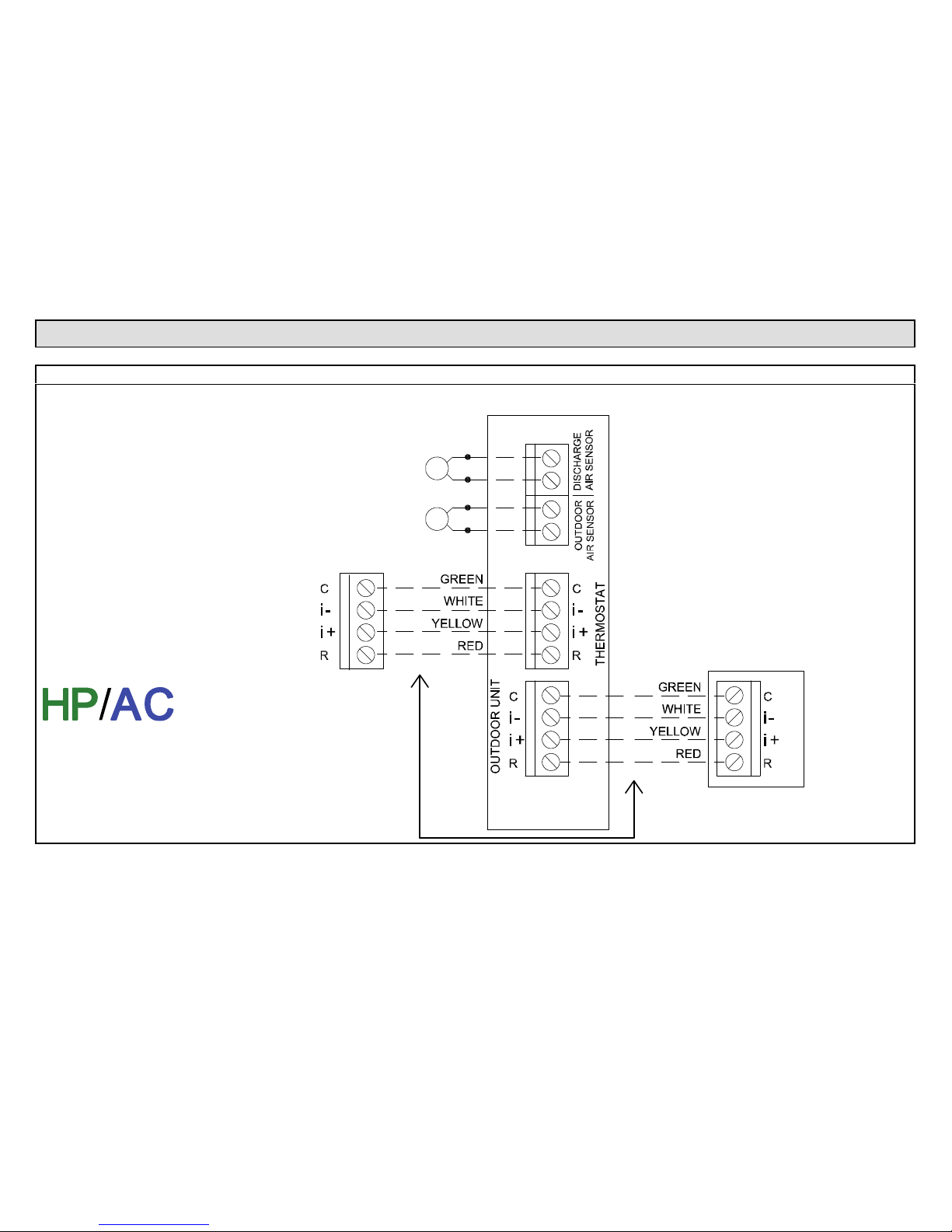
Comfort Sync 7-Day Programmable Communicating Thermostat
27
Wiring Diagrams
Comfort Sync Communicating System Wiring
Comfort Sync
FURNACE (IFC) OR AIR HANDLER (AHC)
Comfort Sync
THERMOSTAT
Comfort Sync
OUTDOOR AIR CON
DITIONING OR HEAT
PUMP UNIT
OPTIONAL OUT
DOOR AIR SENSOR
(SEE OAS NOTE)
OPTIONAL DIS
CHARGE AIR
SENSOR (SEE
DAS NOTE)
Comfort Sync Thermostat
Comfort Sync Indoor Furnace or Air Handler
Comfort Sync Outdoor Condensing Unit or Heat Pump
DAS NOTE - The discharge air sensor is
intended to be mounted downstream of the
furnace heat exchanger and air conditioning
coil. It must be placed in free airflow, where
other accessories (such as humidifiers, UV
lights, etc.) will not interfere with its accur
acy. Wiring distance between the IFC or
AHC and the discharge air sensor should
not exceed 10ft when wired with 18-gauge
thermostat wire.
OAS NOTE - Wiring distance between the
IFC or AHC and the outdoor temperature
sensor should not exceed 200ft when wired
with 18-gauge thermostat wire.
Maximum total length of all connections on
the RSBus is limited to 1500ft.
Wire gauge of RSBus wire is 18.
RSBus
RSBus
Page 28
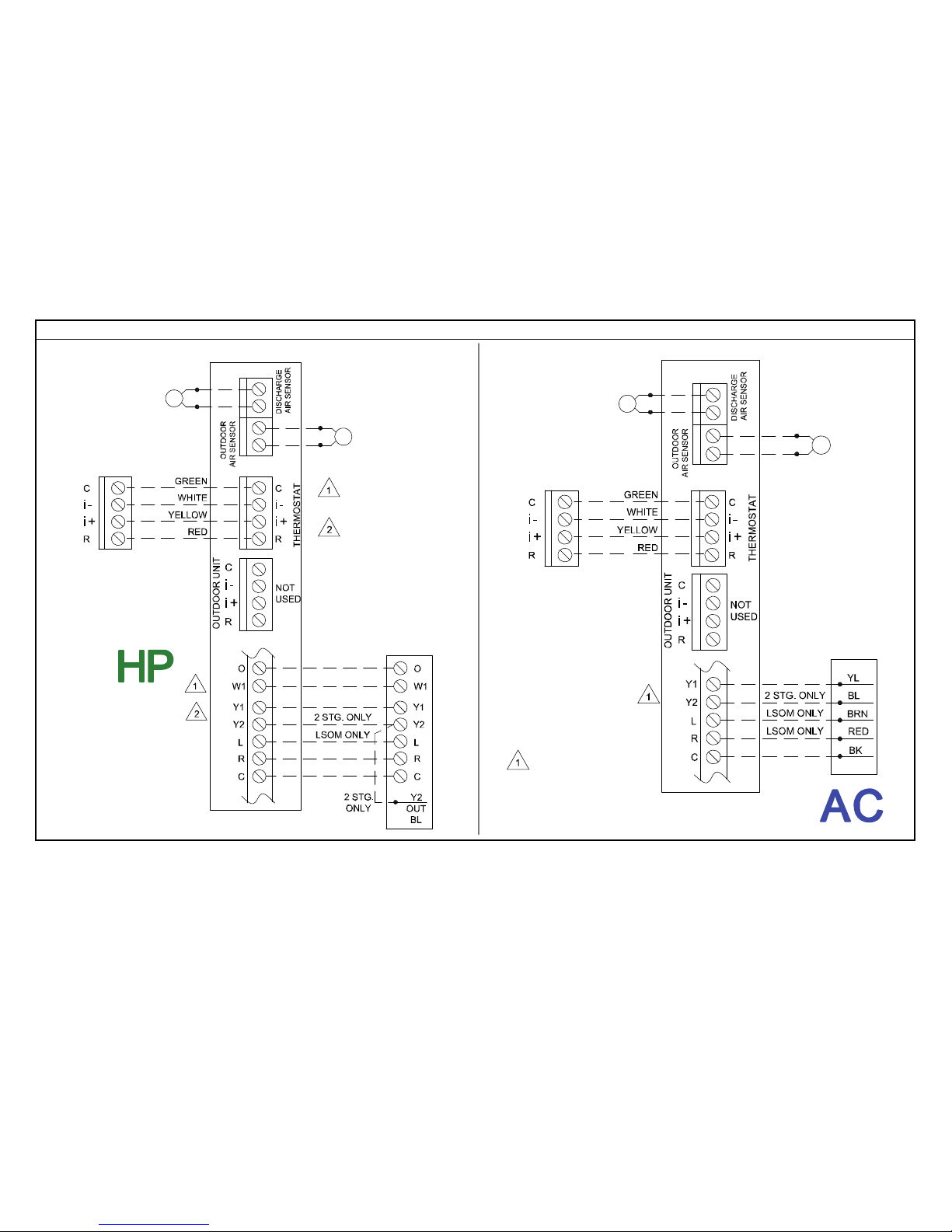
28
Comfort Sync Communicating Indoor / Non-Communicating Outdoor System Wiring
Comfort Sync
Thermostat
Comfort SyncAir
Handler
Standard Outdoor Heat
Pump
STANDARD
OUTDOOR HEAT
PUMP UNIT - 1
OR 2 STAGE
Comfort Sync AIR HANDLER (AHC)
Comfort Sync
THERMOSTAT
Comfort Sync FURNACE (IFC) OR AIR HANDLER (AHC)
Comfort Sync
THERMOSTAT
STANDARD
OUTDOOR AIR
CONDITIONING
UNIT - 1 OR 2
STAGE
Comfort Sync Thermostat
Comfort Sync Indoor Furnace or Air Handler
Standard Outdoor Condensing Unit
OPTIONAL OUT
DOOR AIR SENSOR
OPTIONAL
DISCHARGE AIR
SENSOR
Maximum total
length of all connec
tions on the RSBus
is limited to 1500ft.
Wire gauge of RS
Bus wire is 18.
Maximum total
length of all connec
tions on the RSBus
is limited to 1500ft.
Wire gauge of RS
Bus wire is 18.
RSBus
RSBus
Setup Notes:
Cut Y1-Y2 On-board
Link For 2-stage Out
door Units
Cut R-O On-board Link
For Outdoor Heat Pump
Units
Setup Note:
Cut Y1-Y2 Onboard Link For
2-stage Outdoor
Units
OPTIONAL
DISCHARGE AIR
SENSOR
OPTIONAL OUT
DOOR AIR SENSOR
Page 29
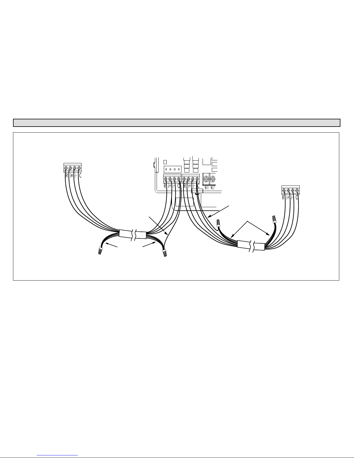
Comfort Sync 7-Day Programmable Communicating Thermostat
29
Thermostat Wire Termination in Communicating System
Indoor Unit
Controller
Outdoor Unit
Comfort Sync
thermostat
Single wire to
terminal C
Single wire to
terminal C
Unused wires
Unused wires
RSBus
Minimum wire size is 18
gauge
Maximum total length of all connections on the RSBus is limited to
1500 ft. (450 m). Max. length between components is 300 ft. (90 m).
Note: Comfort Sync thermostat does not require shielded cable wiring.
BEST PRACTICES! Keep all communication wiring as far away from house electric
al wiring and large electrical appliances as possible (15' [5m] recommended).
Communicating systems using the Comfort Sync thermostat require four
thermostat wires between the thermostat and the furnace/air handler control
and four wires between the outdoor unit and the furnace/air handler control.
When a thermostat cable with more than four wires is used, the extra wires
must be properly connected to avoid electrical noise. The wires must not be
left disconnected.
Use wire nuts to bundle the unused wires at each end of the cable. A single
wire should then be connected to the indoor unit end of the wire bundle and
attached to the “C” terminals as shown in the diagram above.
This is not an issue in non-communicating systems.
Page 30
30
Using the Secure Web Portal
Access all the great Wi-Fi enabled features on your Comfort Sync™
thermostat from our secure web portal.
www.mycomfortsync.com
After signing in, you’ll be able to view your Comfort Sync™ system settings,
adjust the temperature and view reminders and alerts – just as you would on
your Comfort Sync™ thermostat at home. With a familiar look and settings
this simple, you should feel right at home. Don’t forget to check out the
available Apps.
From the web portal welcome page, you may also click on links to launch an
interactive demo or learn more about Comfort Sync™.
Screen-Saver
HOW DO I TURN ON SCREEN-SAVER
1. From the thermostat Home screen, press .
2. Press the display setting button.
3. Press the screen saver button.
4. From the pop-up menu, select on for the screen-saver.
When set to off, the screen stays on.
When set to on, after 30 seconds of inactivity the screen will go
blank
Page 31
Comfort Sync 7-Day Programmable Communicating Thermostat
31
Accessing Installer Screens and Changing Equipment
Parameters
To access the installer screens after the unit has been placed in operation
and the user home screen is displayed, touch the Allied logo and hold for 5
seconds. The system will access the installer screens.
A message screen stating “Qualified equipment installer warning” screen
appears.
1. When pressing yes, the thermostat will search for communicating
devices in the system.
2. When pressing no, the thermostat returns to the main screen.
3. When pressing reset, the thermostat resets all parameters to factory
default, searches for communicating equipment and erases all
information concerning non-communicating equipment previously
stored in the thermostat.
After initial installation, if an alert is present when you are making changes to
settings, no action on the alert is mandatory.
Press equipment if you need to set up equipment parameters and edit
details of devices in the system.
Press diagnostics if you need to analyze the system (see page 12).
If any component of the HVAC system has been changed, e.g. replacing an
outdoor sensor, reconfiguring the system will be required. To begin
reconfiguring a system (after you have accessed the program from the Allied
logo [previous page]), touch the setup button. The “Start system
configuration” screen will appear. Press start to proceed. The “Re-configure
confirmation” screen will appear. This reminder notes that system
configuration may affect some existing device settings and prompts to
confirm or cancel the configuration process.
Press confirm to continue system configuration; the screen will change to
the system discovery screen. At this point, the program goes through the
same setup as the initial setup process which begins on page 3.
NOTE - “Compatible device found” screen (shown below) appears only
when a device has been removed and replaced with a compatible device.
Missing
Device Equipment Type No.
Model No. (control model no.)
Serial No. (control serial no.)
Found Compatible
Device Equipment Type No.
Model No. (control model no.)
Serial No. (control serial no.)
Settings were not copied
ADJUSTING EQUIPMENT PARAMETERS AFTER INITIAL INSTALLER
SETUP
1. From the Home Screen, touch and hold Allied until the warning
screen appears. Press yes to continue.
2. Press equipment to change equipment parameters and edit details of
devices in the system without having to re-run the setup program.
3. Select the equipment button to continue. The system devices screen
will open. Use the arrows to select a device and touch edit.
4. Use the arrows to highlight a setting and then touch edit.
5. When finished, touch back; equipment parameters screen then touch
next. “Select tests to run screen appears"; either run tests as before
or touch skip tests.
 Loading...