

ComfortStar MIA18-13, MIA30-13, MIA24-13, MIA42-13, MIA48-13 Service Manual
...
Service Manual
MIA Series
Condensing Units
Cooling Only
1.5 tons to 5 tons

Comfortstar Service manual for 13seer Cooling Only Condensing
Contents
1. Description of Products & Fearures
2. Physical And Electrical Specifications
3. Safety Caution
4. Application
5. Installation Instructions
6. Maintenance Instructions
7. Service And Troubleshooting
8. Wiring Diagrams
9. Explosive Diagram And Spare Parts List
1
Comfortstar Service manual for 13seer Cooling Only Condensing
1. Description Of Products & Fearures
1.1
Summary
The main components of Condensing UnitS :
Sroll compressor with high efficiency, better reliability, super-quiet operation;
High efficiency heat exchanger with inner groove copper pipe, inserting aluminum fin;
The expansion valve can maintain heating capacity.
Painted and zinc-gilt metal parts with corrosion protection
Compressor overload protection
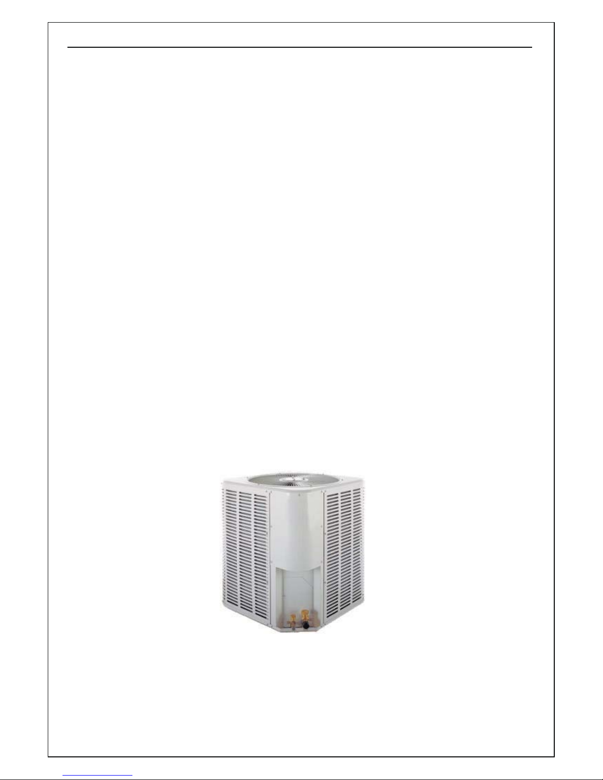
1.2 Condensing Unit Outline
Top discharge air flow with low noise.
Smaller body with high efficiency .
With ULcertification.
Effortless Installation.
Annular outdoor unit,Fast heat dispersion and Powful cooling(heating)
Beautiful outline with powerful antiseptics ability.
Reliable and steady operation.
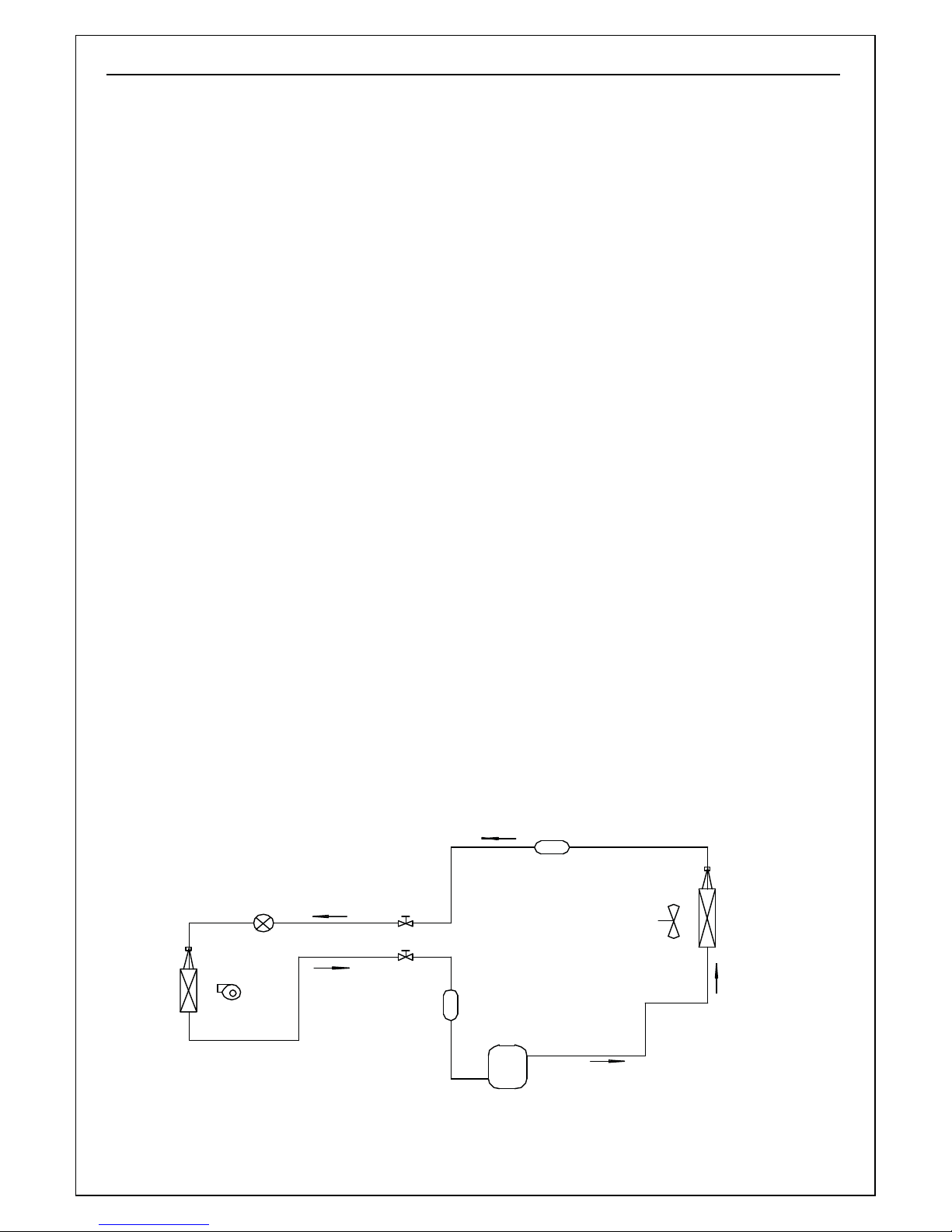
1.3 Working Principle
MIA series (Cooling only ) condensing unit
Service Valve
of Liquid Pipe
Service Valve
of Gas Pipe
Indoor
Heat
Exchanger
Expansion Valve or Piston
Centrifugal
Fan
Fig.1 Working Principle Diagram of Cooling only Condensing Unit
Filter
Compressor
2
Filter
Axial Flow Fan Outdoor
Liquid
Separator
Heat
Exchanger
Comfortstar Service manual for 13seer Cooling Only Condensing
The working principle diagram of the Air Conditioner is shown above in fig.1. When the
system operates in cool mode, the low temperature and low pressure refrigerant gas from the heat
exchanger of the indoor unit is sucked by compressor and compressed, the high temperature and high
pressure gas is discharged into heat exchanger of outdoor unit, heating exchanges with air of outside and
turns into the refrigerant liquid, the liquid is throttled by throttling element and changed into the low
temperature and low pressure liquid then flows into the heat exchanger of indoor unit, heating exchange
with the air of the indoor then turns into the low temperature and low pressure refrigerant gas. The above
circle goes round and round.
3
1, 293 1,939 2,451 2,881 3,250 4,136 5,456
1
Comfortstar Service manual for 13seer Cooling Only Condensing
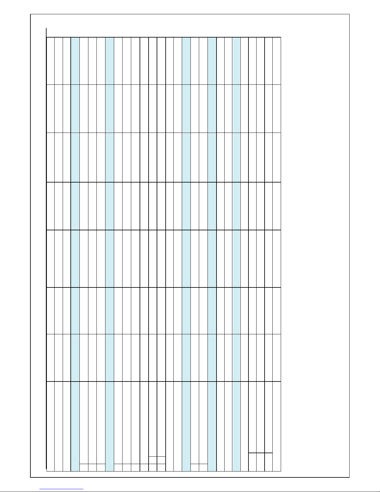
2. Specifications
Model Number MIA18-13 MIA24-13 MIA30-13 MIA36-13 MIA42-13 MIA48-13 MIA60-13
Performance
Cooling Capacity (Btu/h) 17,200 23,000 28,800 36,000 42,000 48,000 60000
Sensible cooling capacity (Btu/h) 14,200 19,500 24,400 28,300 31,000 36,800 43,300
Latent cooling capacity (Btu/h) 3,000 3,500 4,400 7,700 11,000 11.200 16,700
SEER 13 13 13 13 13 13 13
Total Input Watts (Cooling)
Airflow Rate (CFM) 694 850 1,083 1,210 1,448 1,585 1,868
Electrical
Voltage - Phase - Frequency (Hz) 208/230 - 1 - 60 208/230 - 1 - 60 208/230 - 1 - 60 208/230 - 1 - 60 208/230 - 1 - 60 208/230 - 1 - 60 208/230 - 1 - 60
Minimum Circuit Amps 9.0 11.7 15.1 21.8 24.3 27.2 33.4
Maximum Overload Amps 15.0 20.0 25.0 35.0 40.0 45.0 50.0
Compressor
Type / Maker ROTARY ROTARY ROTARY SCROLL SCROLL SCROLL SCROLL
Model Number 2K21S236A6E 2K28S236A6H QP348KBB ZR30KC-PFV-522 ZR36KC-PFV-522 ZR42K3-PFV-522 ZR54K3-PFV-522
RLA (Rated Load Amps) 6.2 8.4 11 .0 16.4 18.4 20.4 25
LRA (Locked Rotor Amps) 38.0 49.0 68.0 84.0 95.0 109.0 148.0
Internal Overload Protection N/A Yes Yes Yes Yes Yes Yes
Crankcase Heater N/A N/A N/A N/A N/A N/A N/A
Fan Motor
RLA (Rated Load Amps) 1.2 1.2 1.3 1.3 1.3 1.7 2.1
Rated House Power (hp) 1/6 1/6 1/5 1/5 1/5 1/4 1/3
Nominal RPM 790 790 830 830 830 890 1100
Output Watts 120.0 120.0 150.0 150.0 150.0 210.0 300.0
Fan
The blade angel 36 36 29 29 29 29 29.5
Diameter (In) 18.0 18.0 22 22 22 22 24
No. of Blade 4 4 4 4 4 4 3
Fan Material ALUMINIUM ALUMINIUM ALUMINIUM ALUM INIUM ALUMINIUM ALUMINIUM ALUMINIUM
Condenser coil
Number or Rows 2 2 2 2 2 2 2
Tube spacings (V x H) (In) 0.5 x 0.75 0.5 x 0.75 0.5 x 0.75 0.5 x 0.75 0.5 x 0.75 0.5 x 0.75 0.5 x 0.75
Fins per Inch - FPI 17 17 17 17 17 17 17
2
25.2(640) 25.2(640) 29.5(750) 29.5(750) 29.5(750) 34.3(870) 39.4(1000)
25.5(648) 25.5(648) 30.3(770) 30.3(770) 30.3(770) 30.3(770) 30.3(770)
25.5 (648) 25.5 (648) 30.3(770) 30.3(770) 30.3(770) 30.3(770) 30.3(770)
Height 23.8 [604] 23.8 [604] 28.3 [718] 28.3 [718] 28.3 [718] 32.7 [830] 32.7 [830]
Width 24 [610] 24 [610] 28[710] 28[710] 28[710] 28[710] 29.5 [750]
Depth 24 [610] 24 [610] 28 [710] 28 [710] 28 [710] 28 [710] 29.5[750]
Liquid Line Dimension (In) 3/8 3/8 3/8 3/8 3/8 1/2 1/2
Comfortstar Service manual for 13seer Cooling Only Condensing
Fin Type Enhanced fins Enhanced fins Enhanced fins Enhanced fins Enhanced fins Enhanced fins Enhanced fins
Tube OD and Type 1/4" Grooved 1/4" Grooved 1/4" Grooved 1/4" Grooved 1/4" Grooved 1/4" Grooved 1/4" Grooved
Gross Finned Face Area (Sq Ft) 8.4 8.4 13.1 13.1 13.1 15.3 19.8
Dimensions
Refrigerant Line
Width
Depth
Outdoor above Indoor Unit 50 50 50 100 100 100 100
Indoor above Outdoor Unit 40 40 40 60 60 60 60
Vapor Line Dimension (In) 5/8 5/8 3/4 3/4 3/4 1-1/8 1-1/8
Max Refrigerant Line Length (Ft) 100 100 100 250 250 250 250
Max Vertical Distance (Ft) 50 50 50 100 100 100 100
Refrigerant Connection Type Jointing Jointing Jointing Jointing Jointing Jointing Jointing
Refrigerant Type / Charge (Oz) R-22 /88 R-22 / 106 R-22 /159 R-22 /155 R-22 /155 R-22 / 176 R-22 / 194
Weight (lbs)
Net 118.8 121 165 182.6 182.6 187 220
Ship 129.8 132 178.2 193.6 193.6 200.2 242
Agency Approvals
7 Performance Certification ARI ARI ARI ARI ARI ARI ARI
Safety Approvals UL UL UL UL UL UL UL
Height
Shipping
Carton Dimensions
Container Loading(40'High) 216 216 135 135 135 135 90
Notes:
1、R-22 Charge for the outdoor unit with matching indoor unit and 25' line set;
2、Rated in accordance with ARI 210-240 and D.O.E. test standards
Comfortstar Service manual for 13seer Cooling Only Condensing
3.Warning
Before operating the Air Conditioner, read this manual thoroughly and operate accordingly.
“CAUTION” and “DANGER” have the following meanings with these instructions:
DANGER
Ć
This mark indicates improper operation might lead to serious injury for the users.
CAUTION
Ć
This mark indicates improper operation might possibly result in personal harm to the
user, or damage to property.
DANGER!
Do not use or place combustible and explosive gas or liquid near the air conditioner.
Do not attempt to install Air Conditioner by yourself to guarantee the Air Conditioner can be
permanent use.
In the event of a malfunction (burning smell, etc.), stop operating immediately and turn off the
power switch.
Do not insert fingers or objects into the outlet port or intake grilles.
Do not check or repair the Air Conditioner when it is running.
Do not sprinkle water on the Air Conditioner or operate it with wet hands.
CAUTION
Before install, ensure the power supply is corresponding to that listed in nameplate and check the
security of the power source.
Before use, ensure the wire connections are proper for avoiding electric shock or fire.
The Air Conditioner should not be operated by children.
Please turn off the power before cleaning the Air Conditioner or replacing the filters.
Turn off power source when not using the Air Conditioner for extended periods.
Do not climb on or place objects on the air conditioner.
Ć
POWER SUPPLY
Adequate power supply, adequate cross section of wire. Please consult it with distributor and
professional.
The Air Conditioner must be reliably earthed! The earth wire must be connected to the special
grounding devices. It is forbidden to connect it to water pipe, gas pipe, wires of the lightning rod
and telephone.
The cable must be wired by qualified personnel in accordance with national wiring regulation.
Electricity leakage protection switch and air switch should be fixed in the wire circuit.
4.Application
Before specifying any air conditioning equipment, a survey of the structure and a heat gain calculation
must be made. A heat gain calculation involves identifying all surfaces and openings that gain heat from the
surrounding air and quantifying that heat gain. It also calculates the extra heat load caused by sunlight and
by humidity removal. These factors must be considered before selecting an air conditioning system to
provide year round comfort. The Air Conditioning Contractors of America (ACCA) J Manual method of load
calculation is one recognized procedure for determining the cooling load. The cooling load calculation
determines the unit size. There are two capacities that enable the equipment to provide comfort. The first is
sensible capacity. How much sensible heat can the unit remove? Sensible heat is the heat energy measured
on the dry bulb thermometer.
The second form of heat is called latent or hidden heat. This is heat held in the humidity in the air.
1

Comfortstar Service manual for 13seer Cooling Only Condensing
Removing this heat does not affect a thermometer. However, removing the heat held in the moisture in the
air greatly increase comfort. A properly sized unit removes both forms of heat, producing a comfortable living
space. An oversized system cycles on and off too quickly and does not properly remove humidify ,
producing an uncomfortable living space. Select the indoor and outdoor equipment combination based on
the manufacturer’s engineering data. After the proper equipment combination has been selected, satisfying
both sensible and latent conditioning requirements, the system must be properly installed. Only then can the
unit provide the comfort the manufacturer built into it.
There are several factors that installers must consider.
? Outdoor unit location
? Proper equipment evacuation
? Outdoor unit refrigerant charge
? Indoor unit air flow
? Indoor unit blower speed
? Supply and return air duct design and sizing
? System air balancing
? Diffuser and return air grille location and sizing
Working Temperature
Indoor unit Outdoor
Max cooling function
Min cooling function
86 115
61
55 (Low ambient control kit should be installed when temperature lower
than 55
Table1
Unit Dimensions
Model 18&24 30&42 48 60
length 24 28 28 29.5
Height 23.8 28.3 32.7 32.7
Table 2
Note:
1.The piston placed in the indoor unit is used when cooling.
2. Expansion Valve placed in the outdoor unit is used for indoor unit when heating.
The air distribution system has the greatest effect. The duct system is totally in the control of the
contractor. The industry can only recommend the correct procedure.
The correct air quantity is critical on air conditioning system. Proper operation, efficiency, compressor
life and humidity control depend on the correct balance between indoor load and outdoor unit capacity. High
indoor air flow increases the possibility of high humidity problems in cooling. Low indoor air flow reduces
total capacity, and causes coil icing. Serious harm can be done to the compressor in either condition.
Air conditioning requires a specified air flow. Each ton of air conditioning requires 400 cubic feet of air
per minute (400CFM/TON).
Duct design and construction should be carefully done. System performance can be lowered
dramatically through bad planning or workmanship. In cooling ,a hot attic can cause a temperature gain of
ğ
inch
2
Comfortstar Service manual for 13seer Cooling Only Condensing
3°in the return duct and 4°in the supply duct. This can reduce the cooling capacity of an air conditioning
system by as much as 30%.This means a loss of almost one ton of cooling capacity from a three ton system.
Air leakage of only 3% in a return duct can cause a 5% loss in system capacity. 3% leakage on a three
ton system is only 30 CFM. Two or three unsealed joints can cause this leak. Sealing the return and supply
ducts pays dividends in increased system capacity and lower operating costs.
Effective duct insulation is essential to prevent loss of capacity and sweating ducts in the cooling mode.
Duct systems installed in the conditioned space can be left uninsulated , but a dense 1/2” fiberglass duct
liner reduces blower and air noises, and prevents sweating ducts when humidity levels are high.
Supply and return duct systems in attics and crawl spaces require a minimum 1” of dense duct liner or
2” fiberglass wrap with a sealed vapor barrier. A leaky vapor barrier results in duct sweating, causing wet
insulation.
Wet insulation does not insulated .Heat transfer through poorly insulated systems can result in over
50% loss in operating capacity. Sweating ducts also promote rusting ducts resulting in premature duct failure.
Other duct materials have been successfully used. Carefully follow the duct manufacturers’ installation
instructions. The duct system is only as good as the planners and installers construct.
Air supply diffusers must be selected and located carefully. They must be sized and positioned to
deliver treated air along the perimeter of the space. If they are too small for their intended air flow the
become noisy. If they are not located properly they cause drafts on the occupants in the rooms. Return air
grilles must be properly sized to carry air back to the blower. If they are too small they also cause noise. The
installers should balance the air distribution system to ensure proper air flow to all rooms in the home. This
ensures a comfortable living space.
5. Installation Instructions
! WARNING
These instructions are intended as an aid to qualified, licensed service personnel for proper installation,
adjustment and operation of this unit. Read these instructions thoroughly before attempting installation or
operation. Failure to follow these instructions may result in improper installation, adjustment, service
or maintenance possibly resulting in fire, electrical shock, property damage, personal injury or
death.
5.1 Outdoor Unit Inspection
This product has been inspected at the factory and released to the transportation agency without known
damage. Inspect exterior of carton for evidence of rough handling in shipment. Unpack carefully. If damage
is found, report immediately to the transportation agency.
5.2 Equipment Protection From Environment
The metal parts of the unit may be subject to rust or corrosion in adverse environmental conditions. This
oxidation could shorten the unit life. Salt spray or mist in seacoast areas, sulphur or chlorine from lawn
watering systems and various chemical contaminants from industries such as paper mills and petroleum
refineries are especially corrosive.
If the unit is to be installed in an area where contaminants are likely to be a problem, special attention should
be given to the equipment location and exposure.
3
 Loading...