

Page 1
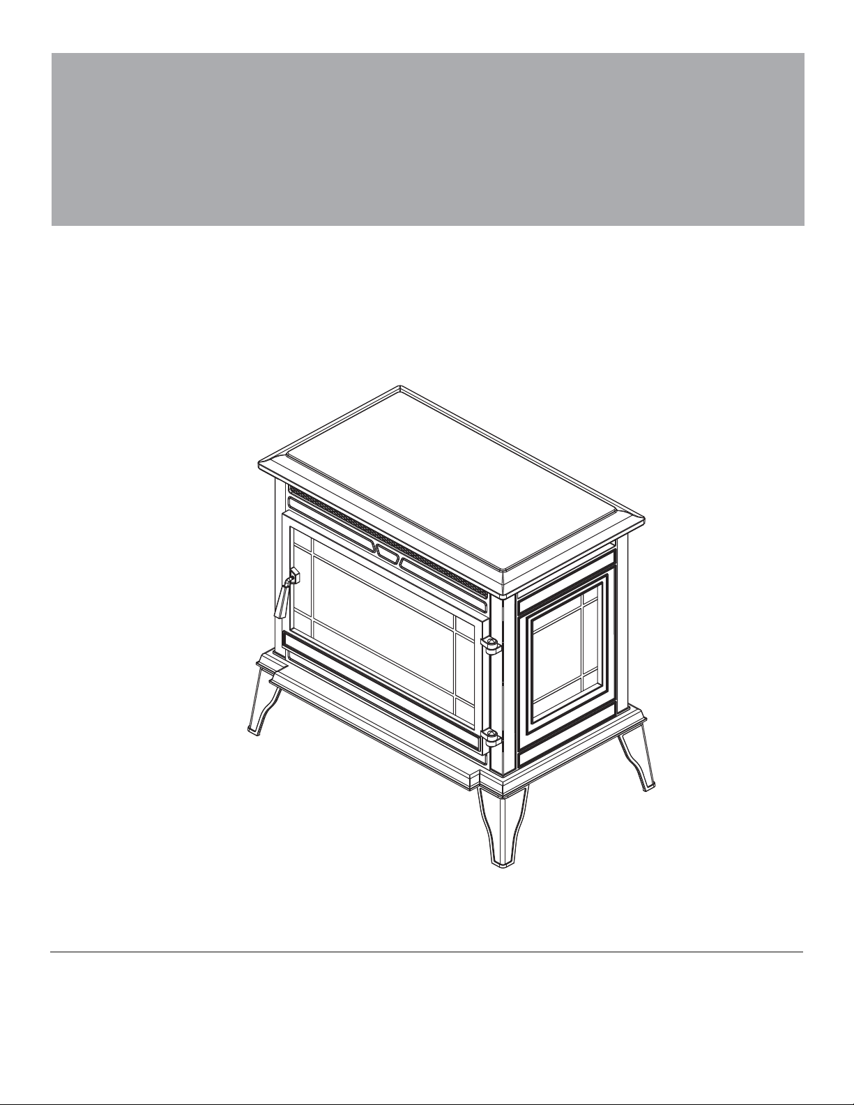
Electric Stove
ASSEMBLY, CARE & USE INSTRUCTIONS
MODEL #: CS-25IR-BLK; CS-25IR-BRZ; CS-25IR-CRM
Date Purchased
ETL Basic Model SP5465
Questions, problems, missing parts?
Before returning to your retailer,
call our customer service department at
1-855-571-1044
_______________________
9 a.m. - 5 p.m., EST, Monday - Friday.
Page 2
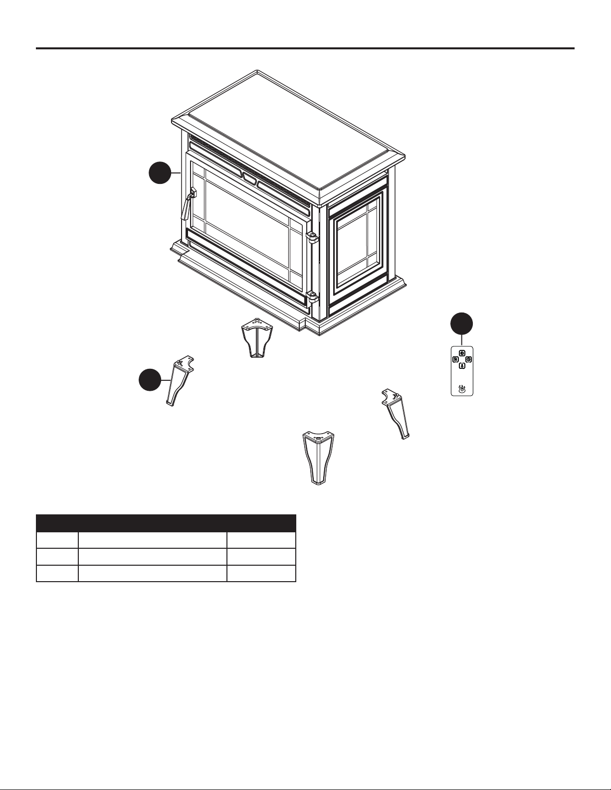
PACKAGE CONTENTS
A
C
B
PART QUANTITY
DESCRIPTION
A Body 1
B Leg 4
C Remote Control 1
2
Page 3
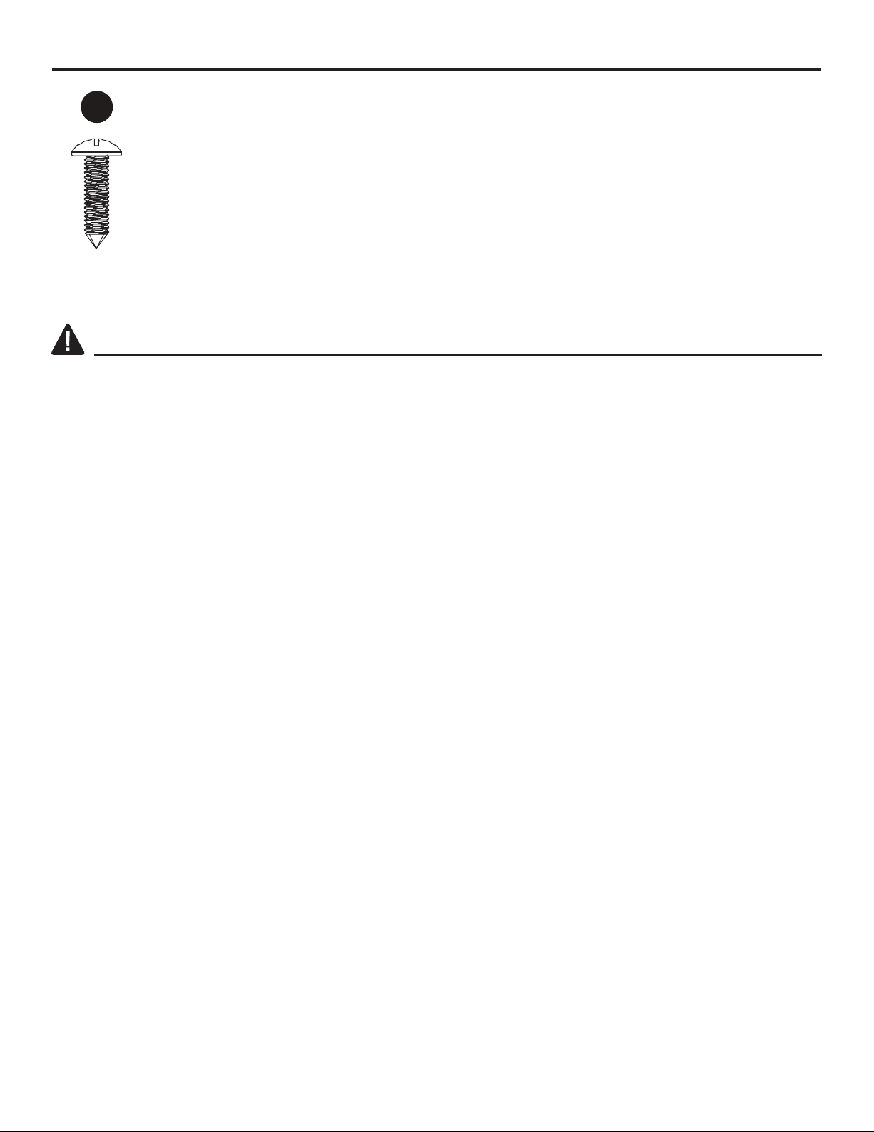
HARDWARE CONTENTS (not shown actual size)
AA
Screw
Qty. 12
SAFETY INFORMATION
Please read and understand this entire manual before attempting to assemble, operate or install the
product.
This equipment has been tested and found to comply with the limits for Class B digital devices,
pursuant to part 15 of the FCC rules. These limits are designed to provide reasonable protection
against harmful interference in a residential installation. The equipment generates, uses and can
radiate radio frequency energy and, if not installed and used in accordance with the instructions, may
cause harmful interference to radio or television reception, which can be determined by turning the
equipment off and on. The user is encouraged to try and correct the interference by one or more of
the following measures:
• Reorient or relocate the receiving antenna
• Increase the separation between the equipment and the receiver
• si reviecer eht hcihw ot taht morf tnereffid tiucric a no teltuo na otni tnempiuqe eht tcennoC
connected.
• .pleh rof naicinhcet VT/oidar decneirepxe na ro relaed eht tlusnoC
This device complies with Part 15 of the FCC rules. Operation is subject to the following two
conditions:
1. This device may not cause harmful interference, and
esuac yam taht ecnerefretni gnidulcni ,deviecer ecnerefretni yna tpecca tsum ecived sihT .2
undesired operation.
Modifications not approved by the party responsible for compliance could void user’s authority to
operate the equipment.
This Class B digital apparatus complies with Canadian ICES-003.
3
Page 4

SAFETY INFORMATION
IMPORTANT INSTRUCTIONS
When using electric appliances, basic precautions should always be followed to reduce the risk of
fire, electric shock, and injury to persons, including the following:
WARNING
• .retaeh siht gnisu erofeb snoitcurtsni lla daeR
• ,kcohs lacirtcele ro gnitrats detcepxenu morf yrujni diova oT DO NOT plug the power cord into a
source of power during unpacking and assembly. The cord must remain unplugged whenever you
are adjusting / assembling the item.
• ,degamad ro gnissim si trap yna fI DO NOT attempt to use or plug in the power cord until
the missing or damaged part is correctly replaced. To avoid electric shock, use only identical
replacement parts, and when servicing use double-insulated tools.
• ro nerdlihc fi yrassecen si noituac emertxe ,dednettanu dna gnitarepo tfel si meti eht revenehW
invalids are nearby.
• ot snoitaluger elbacilppa rehto dna sedoc gnidliub lacol htiw ylpmoc tsum gniriw teltuo lacirtcelE
reduce the risk of fire, electric shock and injury to persons.
•
Disconnect power before attempting any maintenance or cleaning to reduce the risk of fire,
electrical shock or personal injury.
• This appliance is hot when in use. To avoid burns, DO NOT let bare skin touch hot surfaces. If provided,
use handles when moving this heater. Keep combustible material, such as furniture, pillows, bedding,
papers, clothes and curtains at least 3 feet from this appliance and keep them from the sides and rear.
• latnem ro yrosnes ,lacisyhp decuder htiw snosrep
capabilities, or lack of experience and knowledge, unless they have been given supervision or
instruction.
• DO NOT run cord under carpeting. DO NOT cover cord with throw rugs, runners or similar coverings.
DO NOT route cord under furniture or appliances. Arrange cord away from traffic areas and where it
will not be tripped over.
• DO NOT insert or allow foreign objects to enter any ventilation or exhaust opening as this may cause
an electric shock or fire, or damage the appliance.
• This appliance has hot and arcing or sparking parts inside. DO NOT use it in areas where gasoline,
paint or flammable vapors or liquids are used or stored. This item should not be used as a drying
rack for clothing. Christmas stockings or decorations should not be hung in the area of it.
• Use this appliance only as described in the manual. Any other use is NOT recommended by the
manufacturer and may cause fire, electric shock or injury to persons.
CAUTION
• Cold climate installation recommendation: When installing this unit against a non-insulated
exterior wall or chase, it is mandatory the outer walls be insulated to conform to applicable
insulation codes.
• lacirtcele ynA .ecnanetniam rotom htiw gnideecorp erofeb ffo denrut si rewop eht erus ekaM
repairs or rewiring of this unit should be carried out by a licensed electrician in accordance with
national and local codes.
• gnidoc roloc ,gnituor eriw lanigiro eht ,gniriw ro tnenopmoc lacirtcele yna gnicalper ro gniriaper fI
and securing locations must be followed.
• DO NOT
technician to inspect the item and replace any part of the electrical system.
• ,erif elbissop a tneverp oT DO NOT block air intakes or exhaust in any manner. DO NOT use on soft
surfaces, like a bed, where openings may become blocked.
• ”FFO“ eht ot hctiws rewop niam eht nrut tsriF .ecnailppa siht g
position. Then remove the electrical plug from the wall outlet.
use this item if any part of it has been under water. Immediately call a qualified service
nicivres nehw ffo rewop eht nruT
ro nerdlihc yb desu eb ot ton si ecnailppa ehT
4
Page 5
SAFETY INFORMATION
• If possible, ALWAYS unplug this appliance when not in use.
• DO NOT use outdoors.
• This item is not intended for use in bathrooms, laundry areas and similar indoor locations.
NEVER place heater where it may fall into a bathtub or other water container.
• To disconnect this appliance, turn controls to the off position, then remove plug from outlet.
• ONLY connect to properly grounded outlets.
• This appliance, when installed, must be electrically grounded in accordance with local codes, with
the current CSA C22.1 Canadian Electrical Code or follow U.S.A. Installations, follow local codes
and the National Electrical Code, ANSI/NFPA N0.70.
• lamronba ro staehrevo erutarepmet renni eht nehW .meti eht edisni retimil tatsomreht a si erehT
heating occurs, the thermostat protective device would cut off power supply to prevent damage or
risk of fire.
To prevent a possible fire,
• DO NOT block air intakes or exhaust in any manner. DO NOT use on soft
surfaces, like a bed, where opening may become blocked.
• The heaters MUST NOT be located immediately below a socket-outlet.
• Do not operate any heater with a damaged cord or plug or after the heater malfunctions, has been
dropped or damaged in any manner. Discard heater, or return to authorized service facility for
examination and/or repair.
Electrical Connection
SPECIFICATIONS
Voltage Amps Watts (max.)
120 VAC, 60 Hz 12.5 Amps 1500 Watts
• meti eht ,ylbareferP .deriuqer si teltuo dednuorg ylreporp a htiw tiucric zH 06 ,tlov-021 ,pma-51 A
will be on a dedicated circuit as other appliances on the same circuit may cause the circuit breaker
.tf-6 htiw dradnats semoc tinu ehT .noitarepo ni si retaeh eht nehw wolb ot esuf eht ro pirt ot
three-wire cord, exiting from the rear of the heater. DO NOT exceed the current rating of the current
tap. ALWAYS plug heaters directly into a wall outlet/receptacle. NEVER use with an extension cord
or relocatable power tap (outlet/power strip).
SAVE THESE INSTRUCTIONS
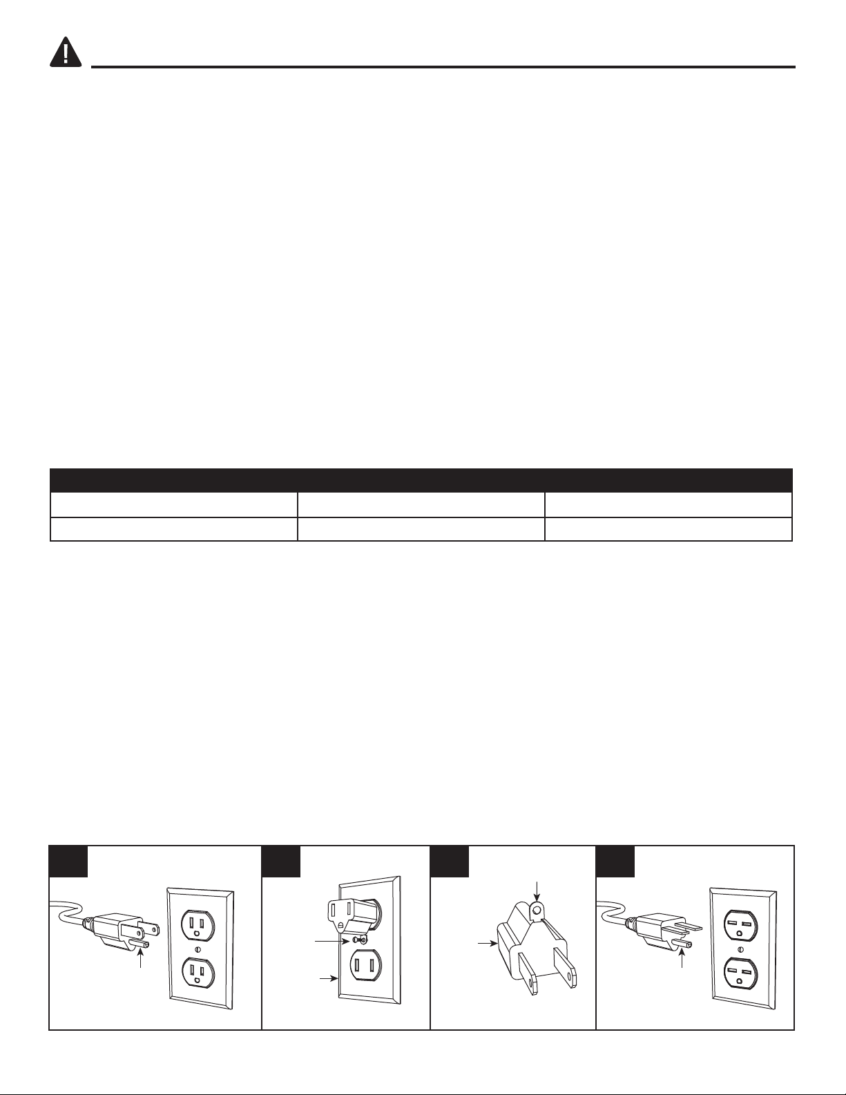
GROUNDING INSTRUCTIONS
• rof noitartsulli eeS .woleb nwohs sa gulp a sah droc ehT .stlov 021 no esu rof si retaeh sihT
grounding instruction. An adapter as shown at C is available for connecting three-blade grounding
type plugs to two-slot receptacles. The green grounding lug extending from the adapter must be
connected to a permanent ground such as a properly grounded outlet box. The adapter should not
be used if a three-slot grounded receptacle is available.
A B C D
Metal
Screw
Grounding Pin Grounding Pin
Cover of
Grounding
Box
Adapter
5
Grounding Means
Page 6
PREPARATION
2
Screw
Qty. 12
Before beginning assembly of product, make sure all parts are present. Compare parts with package
contents list and hardware contents list. If any part is missing or damaged, do not attempt to
assemble the product.
Estimated Assembly Time: 15 minutes
Tools Required for Assembly (not included): Phillips screwdriver
ASSEMBLY INSTRUCTIONS
CAUTION:
Be careful not to scratch the top surface of stove.
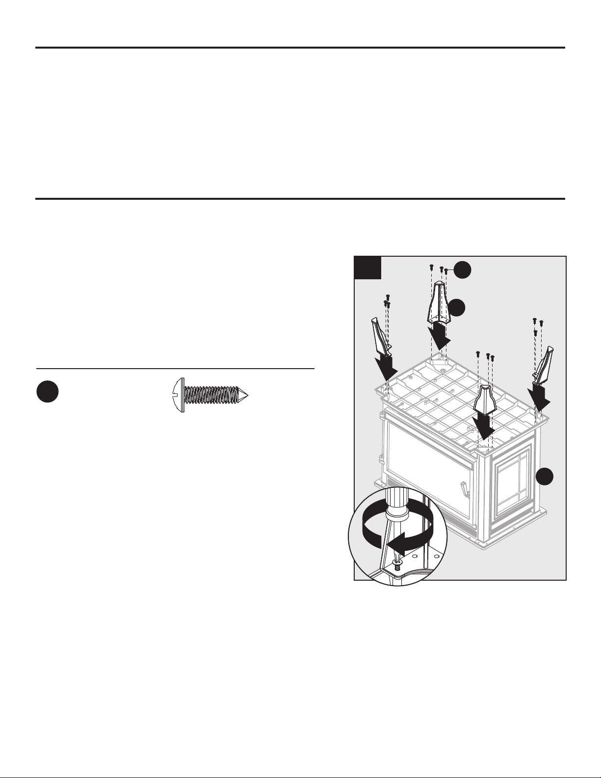
body (A). Secure each leg with three screws (AA).
Assembly is complete. With the help of another
person, flip the unit back right-side up.
Hardware Used
AA
With the help of another person, rest the unit upside down on a soft, flat, level surface.
Screw
x 12
eht fo esab eht no seloh eht otni )B( sgel eht tresnI .1
1
AA
B
1
1
1
1
A
6
Page 7
OPERATING INSTRUCTIONS
M
M
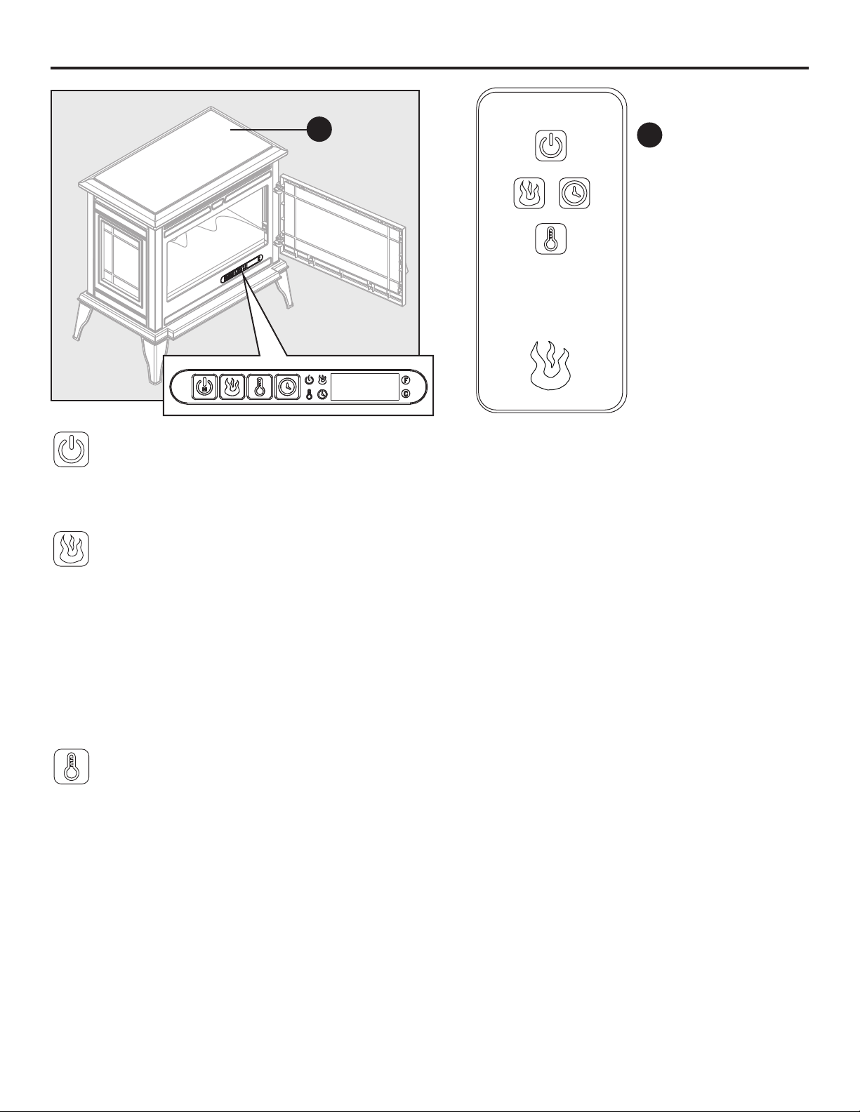
Power Button
M
A
Body
C
M
Remote Control
• Press the power button to turn the main power to the unit ON or OFF.
• When the unit is turned ON, the lights under the emberbed will light to indicate the unit has power.
Flame Brightness Button
• ehT .tinu eht NO rewop ot nottub ssenthgirb emalf eht sserp nac uoy ,FFO derewop si tinu eht fI
emberbed will glow at the brightest setting unless a different setting was saved in the
memory.
Press the button again to scroll through the flame brightness settings, 1, 2, 3, 4, 5 and OFF.
••
Hold down the flame button for 5 seconds to toggle between 5°F (3°C) increments and 1°F (1°C)
increments when setting the temperature. The unit will beep to indicate that the change has taken
place. The factory default temperature is 5°F (3°C) increments.
Temperature Button
• .tatsomreht retaeh eht slortnoc nottub erutarepmet ehT
• ehT .tinu eht NO rewop ot nottub erutarepmet eht sserp nac uoy ,FFO derewop si tinu eht fI
emberbed will glow at the lowest setting unless a different setting was saved in the
memory.
• The thermostat setting range is 65ºF(18ºC) to 90ºF(32ºC), HI(High) and OFF
• 5 rof nottub erutarepmet eht nwod dloH
seconds to toggle between Fahrenheit and Celsius. A
small “F” or “C” will display next to the temperature.
•
.noitcnuf retaeh eht egagnesid ot sdnoces 01 rof nottub ERUTAREPMET eht dloh dna sserP
Press and hold the button for 10 seconds again to engage the heater function. (See
HEATER OVERRIDE section below for more details).
7
Page 8

OPERATING INSTRUCTIONS
Timer Button
• .rewop niam s'tinu eht rof nwodtnuoc eht tes ot desu eb dluohs nottub remit ehT
• debrebme ehT .tinu eht NO rewop ot nottub remit eht sserp nac uoy ,FFO derewop si tinu eht fI
will glow at the lowest brightness setting unless a different setting was saved in the memory.
• ,h5 ,h4 ,h3 ,h2 ,h1 ,03 :era hcihw ,sgnittes remit eht hguorht llorcs ot niaga nottub remit eht sserP
6h, 7h, 8h, 9h and OFF. ( 30 means 30 minutes)
• ni sgnittes eht niatniam lliw dna rewop niam eht FFO nrut lliw ti ,orez sehcaer remit eht nehW
memory.
Memory Function
• .devas eb lliw )remit gnidulcxe( sgnittes noitcnuf lla ,FFO derewop si tinu eht nehW
• etomer eht no ro lenap lortnoc tresni eht no ecno nottub rewop eht gnisserp ,FFO si tinu eht nehW
control will turn the unit ON and "wakeup" the saved function settings.
• tsal eht ta noitcnuf laudividni eht "puekaw" ot nottub noitcnuf yna sserp ,FFO si tinu eht nehW
saved setting. Press the button again to adjust it and press the main power button on the insert or
on the remote control to turn the unit OFF and save the new setting into memory.
• repmet a fI .gnittes erutarepmet devas eht wohs lliw tuodaer DEL eht ,NO derewop si tinu eht nehW
-ature setting was not saved, it will show the flame brightness setting saved in memory. If neither
one has a setting saved to memory, then only the emberbed will glow (as a power light indicator).
• siht nehW .emit yna ta sdnoces 5 rof nottub rewop niam eht nwod dloh ,yromem eht teser oT
happens, the LED readout will blink with four zeros three times.
• .llaw eht morf tinu eht gulpnu ot si yromem eht teser ot yaw rehtonA
HEATER OVERRIDE
The power to the heater can be disengaged to prevent the heater from being accidentally or
unintentionally powered on. This feature is primarily added to help prevent children from powering
on the heater when it is not desired.
• .sdnoces 01 rof nottub erutarepmeT eht dloh dna sserp noitcnuf edirrevo retaeh eht egagne oT
The symbol E3 will display and then go blank while beeping 3 times. The heater function is now
locked. If the heater incon is pressed again E3 will appear then fade. The Flame, Downlight and
Timer functions will operate normally. Only the heater and blower are disengaged.
• To unlock the heater function, press and hold the Temperature button for 10 seconds. The symbol
E3 will display and then go blank while beeping 3 times. The heater function is now engaged.
By pressing the Temperature button again you will be able to adjust the heat temperature to your
desired temperature.
8
Page 9
CARE AND MAINTENANCE
•
Make sure the unit is turned OFF, unplugged and the heating elements of Electric stove are cool
whenever you are cleaning the heater .
.htolc naelc ,tfos denepmad-retaw a gnisu mirt latem eht naelC • DO NOT use brass polish or
household cleaners as these products will damage the metal trim.
•
The motors used on the fan and the flame generator assembly are pre-lubricated for extended
bearing life and require no further lubrication. However, periodic cleaning/vacuuming of the fan/
heater and air intake/output vents is recommended.
•
When the stove is not in use, the heater should be stored in a dry location, away from possible
damage. The power cord should be stored properly to avoid contact with hot or sharp objects.
Any other servicing should be performed by an authorized service representative.
•
Replacing the Remote Control Battery
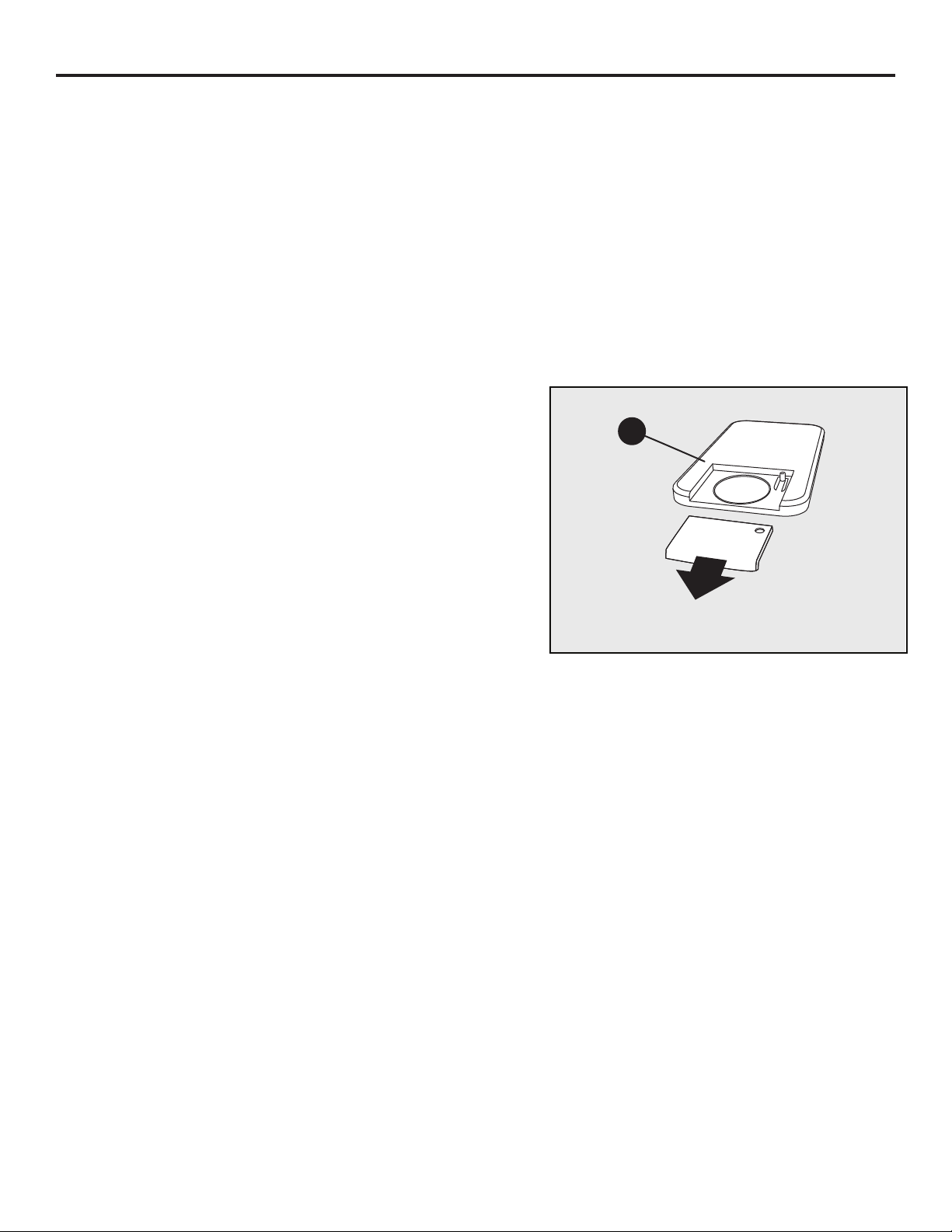
When the remote control (C) stops operating or its
range seems reduced, it is time to replace the
C
battery. Note: The battery should be removed if the
product is to be left unused for a long time.
BATTERY
dne kcab eht no detacol si tnemtrapmoc yrettab ehT .1
of the remote control (C).
Depress and hold the release tab on the battery
.2
compartment, and slide to open.
3.
Remove the old battery.
,)dedulcni ton( yrettab muihtil 5202RC wen a tresnI .4
checking that the + and - sides of the battery match
the inside of the battery compartment.
5. Re-insert the battery door.
9
Page 10
CARE AND MAINTENANCE
Disposal of Used Battery
A battery may contain hazardous substances that could be endangering to environment and
human health.
• yrettab desu taht setacidni gnigakcap ro/dna yrettab eht no dekram lobmys sihT
shall not be treated as municipal waste. Instead it shall be left at the appropriate
collection point for recycling.
• tneverp pleh lliw uoy ,yltcerroc fo desopsid si yrettab desu eht gnirusne yB
potential negative consequences for the environment and human health. The
recycling of materials will help to conserve natural resources.
For more information about collection and recycling of used battery, please contact your local
municipality, your waste disposal service or the point of sale where you purchased this point.
TROUBLESHOOTING
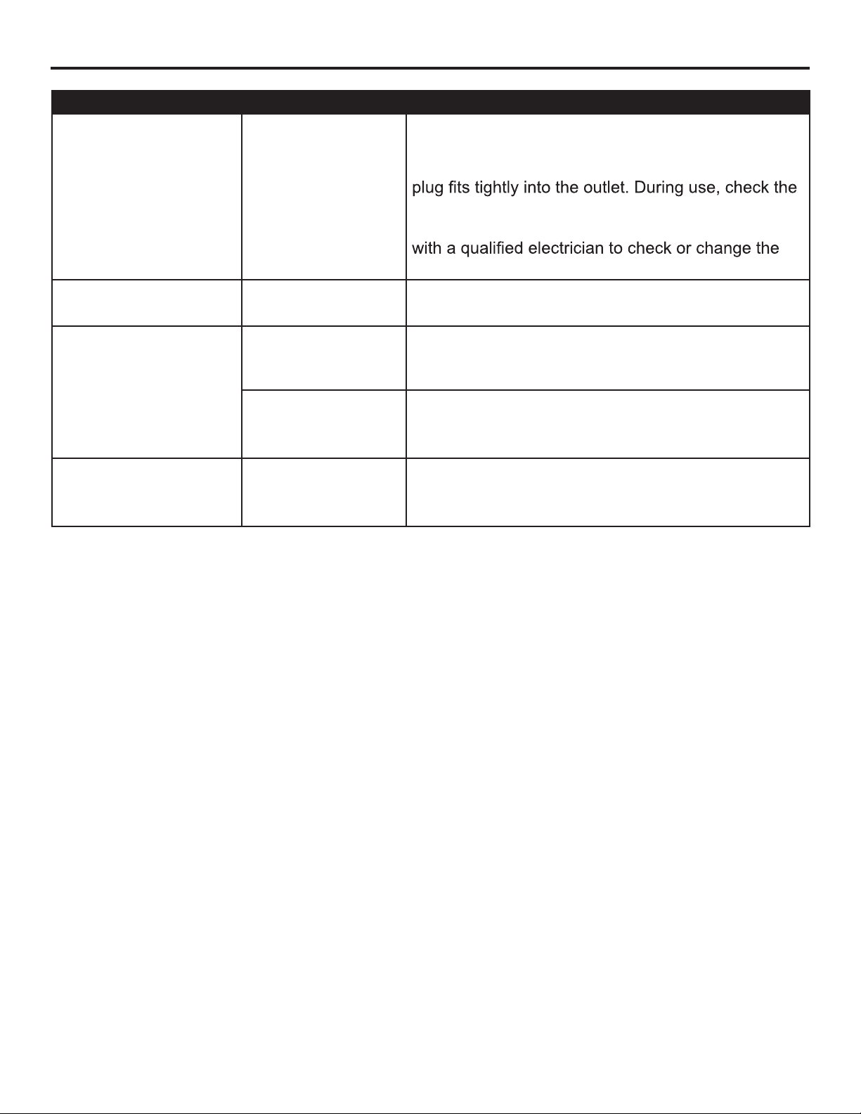
PROBLEM POSSIBLE CAUSE CORRECTIVE ACTION
Error E1 displayed on
control panel.
The overheat
sensor has been
engaged.
Unplug unit, wait 15-20 minutes, then the sensor will
reset itself. Plug the unit back in and turn on the
heater. If the problem persists, call customer service.
Note: The other functions will work normally excluding
the heater. Until the problem is solved, the error will
only appear/sound when the heater button is pressed.
Error E2 displayed on
control panel.
Error E3 displayed on
control panel.
No power; logs do not
glow.
No flame effect but logs
are glowing.
Heater and blower
do not power on but
rest of functions are
working.
The thermostat
sensor is broken
or not working
correctly.
Heater override
function is engaged
The unit does not
have power.
The flame effect is
powered off.
Heater override
function is engaged
Unplug unit, wait 15-20 minutes, then the sensor will
reset itself. Plug the unit back in and turn on the
heater. If the problem persists, call customer service.
Note: The other functions will work normally excluding
the heater. Until the problem is solved, the error will
only appear/sound when the heater button is pressed.
To unlock the heater, simply press and hold the
temperature button for 10 seconds (See page 8
Heater Override Section for more details).
Check that the power cord is securely plugged into a
standard 120V outlet. Then check to make sure the
unit is powered on.
Push the flame brightness button until desired level
is acheived.
To unlock the heater, simply press and hold the
temperature button for 10 seconds (See page 8
Heater Override Section for more details).
10
Page 11
TROUBLESHOOTING
PROBLEM POSSIBLE CAUSE CORRECTIVE ACTION
Power cord gets warm
to the touch.
Normal operation. This is normal for a heater appliance as it requires
more current to operate. Check the connections of
the appliance cord and the outlet. Make sure the
plug and outlet frequently to determine if it is HOT;
if so, discontinue use of the appliance and consult
overheating outlet(s).
Remote control does
not work.
Weak or failing
battery.
Replace with a new battery. (See page 9
for more information.)
Remote control
signal is weak and only
works sometimes.
Fan motor continues
to blow after unit is
powered off.
Pressing the buttons
too quickly.
Using the remote
control too far away
or at an off angle.
Press the buttons slowly and steadily to ensure the
transmitter recognizes the request.
Move closer to the insert; the remote control will only
work within a distance of 20 feet and 45 degrees to
either side from the front of the heater.
Normal operation. This is a standard feature; the blower runs for an
additional time to cool off heater tubes.
11
Page 12

ONE-YEAR LIMITED WARRANTY
The manufacturer warrants that your new Electric Stove is free from manufacturing and material
defects for a period of one year from date of purchase, subject to the following conditions and
limitations.
Install and operate this Electric Stove in accordance with the installation and operating instructions
furnished with the product at all times. Any unauthorized repair, alteration, willful abuse, accident, or
misuse of the product shall nullify this warranty.
This warranty is non-transferable, and is made to the original owner, provided that the purchase was
made through an authorized supplier of the product.
The warranty is limited to the repair or replacement of part(s) found to be defective in material or
workmanship, provided that such part(s) have been subjected to normal conditions of use and
service, after said defect is confirmed by the manufacturer’s inspection.
The manufacturer may, at its discretion, fully discharge all obligations with respect to this warranty by
refunding the wholesale price of the defective part(s).
Any installation, labor, construction, transportation, or other related costs/expenses arising from
defective part(s), repair, replacement, or otherwise of same, will not be covered by this warranty, nor
shall the manufacturer assume responsibility for same.
The owner/user assumes all other risks, if any, including the risk of any direct, indirect or
consequential loss or damage arising out of the use, or inability to use the product, except as
provided by law.
All other warranties – expressed or implied –with respect to the product, its components and
accessories, or any obligations/liabilities on the part of the manufacturer are hereby expressly
excluded.
The manufacturer neither assumes, nor authorizes any third party to assume on its behalf, any other
liabilities with respect to the sale of the product.
The warranties as outlined within this document do not apply to non accessories used in conjunction
with the installation of this product.
This warranty is void if:
The Electric Stove is subjected to prolonged periods of dampness or condensation.
2. Any unauthorized alteration, willful abuse, accident, or misuse of the product.
3. You do not have the original receipt of purchase.
12
Page 13
REPLACEMENT PARTS LIST
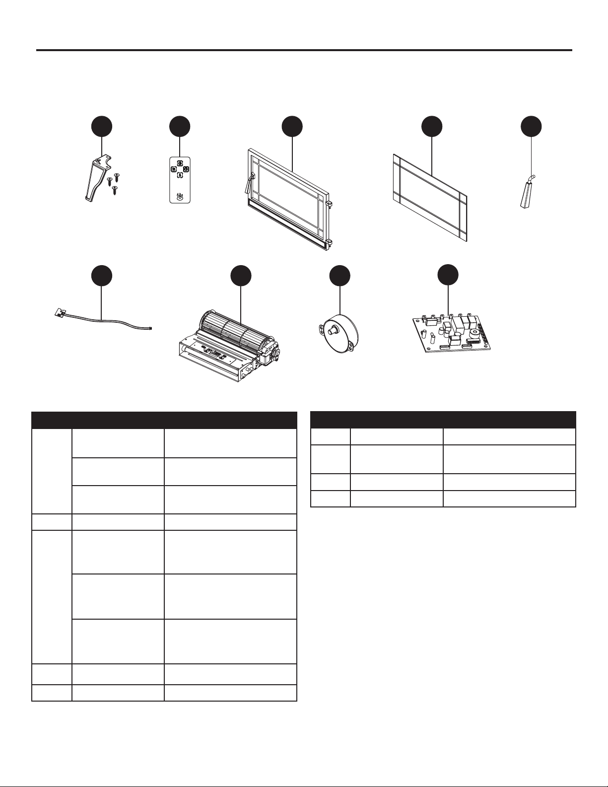
For replacement parts, call our customer service department at 1-855-571-1044, 9 a.m. - 5 p.m., EST,
Monday - Friday.
B C D E F
G H I
PART DESCRIPTION PART #
Leg (with screws)
for CS-25IR-BLK
Leg (with screws)
B
for CS-25IR-BRZ
Leg (with screws)
for CS-25IR-CRM
C Remote Contro l PH-1008ST-24-RC
Door and hinge
pins (2) for
CS-25IR-BLK
PF-1008ST-24-102-001
PF-1008ST-24-104-001
PF-1008ST-24-106-001
PF-1008ST-24-102-002
J
PART DESCRIPTION PART #
G Thermostat
Heater/ Blower
H
Assembly
I Spinner Motor
J PCB Board PH-1008ST-24-008
PH-1008ST-24-005
PH-1008ST-24-006
PH-1008ST-24-007
Door and hinge
pins (2) for
D
CS-25IR-BRZ
Door and hinge
pins (2) for
CS-25IR-CRM
E Door Glass PF-1008ST-24-003
F Door Handle PF-1008ST-24-004
PF-1008ST-24-104-002
PF-1008ST-24-106-002
13
 Loading...