

Page 1
TECHNICAL MANUTECHNICAL MANU
TECHNICAL MANU
TECHNICAL MANUTECHNICAL MANU
TM
ALAL
AL
ALAL
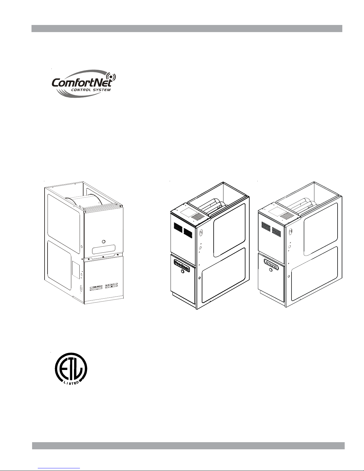
ADVC8/AMVC8
GMVC8
80% Gas Furnace Units
• Refer to Service Manual RS6200004 for installation, operation, and troubleshooting information.
• All safety information must be followed as provided in the Service Manual.
• Refer to the appropriate Parts Catalog for part number information.
• Models listed on page 3.
®
C
This manual is to be used by qualified, professionally trained HVAC technicians only. Goodman does
not assume any responsibility for property damage or personal injury due to improper service
procedures performed by an unqualified person.
US
Copyright ©2009-2010 Goodman Manufacturing Company, L.P.
RT6622012 Rev. 1
April 2010
Page 2
PRODUCT IDENTIFICATION
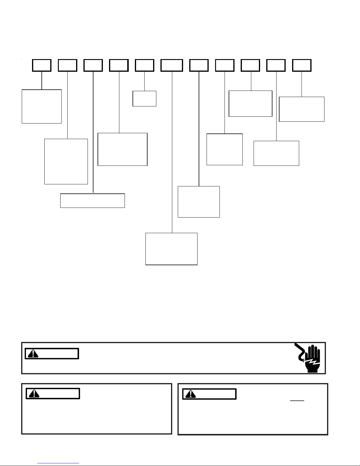
The model and manufacturing number are used for positive identification of component parts used in manufacturing.
Please use these numbers when requesting service or parts information.
GMVC80704CXAA
PRODUCT
TYPE:
G: Goodman®
A: A m ana®
Brand Gas
SUPPLY TYPE:
C: Counterflow/
Horizontal
D: Dedicate
Down flow
M: Upflow/
Horizontal
COMMUNICATI ON
FEATURE:
C: 4-wire
Comm unic ation
Ready
FURNACE TYPE:
V: Variable Speed
AFUE
8: 80%
NOMINAL INPUT:
045: 45,000 Btuh
070: 70,000 Btuh
090: 90,000 Btuh
115: 115,000 B tuh
CABINET
W IDTH:
C: 21"
D: 24-1/2"
AIRFLOW
CAPABILITY:
3: 1200
4: 1600
5: 2000
ADDITIONAL
FEATURES:
X: Low NOx
B: 17-1/2"
N: Natural Gas
A: Initial R eleas e
A: Initial Release
MAJOR
REVISI O N
LEVEL
MINOR
REVISI O N
LEVEL
WARNING
WARNING
WARNING
WARNING
arising from improper service or service procedures. If
you install or perform service on this unit, you assume
responsibility for any personal injury or property damage
which may result. Many jurisdictions require a license to
install or service heating and air conditioning equipment.
Disconnect ALL power before servicing or installing this unit. Multiple power
sources may be present. Failure to do so may cause property damage, personal
injury or death.
Goodman will not be responsible
for any injury or property damage
2
HIGH VOLTAGE!
WARNING
WARNING
viduals meeting the requirements of an "entry level technician", at a minimum, as specified by the Air-Conditioning,
Heating, and Refrigeration Institute (AHRI). Attempting to
install or repair this unit without such background may
result in product damage, personal injury or death.
Installation and repair of this unit
should be performed
ONLY by indi-
Page 3
PRODUCT IDENTIFICATION
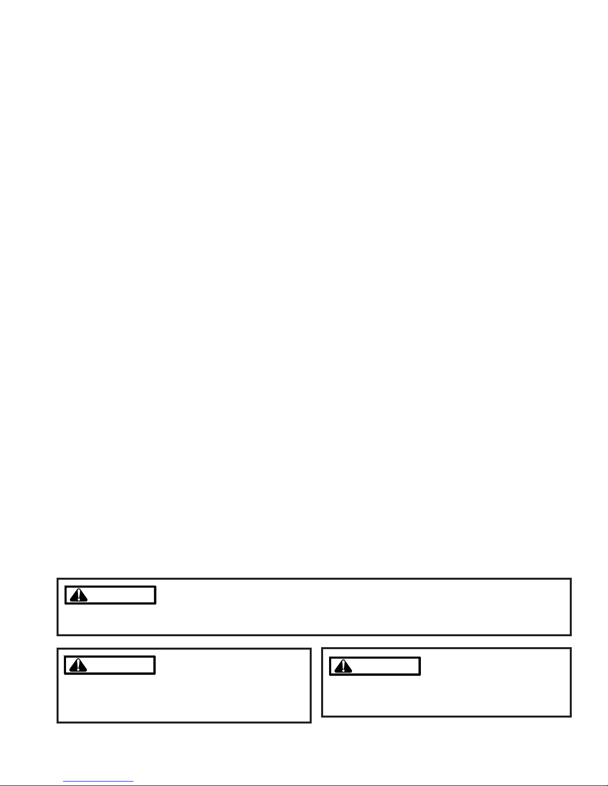
The model and manufacturing number are used for positive identification of component parts used in manufacturing. Please
use these numbers when requesting service or parts information.
AMVC80704BXAA
AMVC80905CXAA
AMVC81155CXAA
AMVC80704BXAB
AMVC80905CXAB
AMVC81155CXAB
ADVC80703BXAA
ADVC80905CXAA
ADVC81155CXAA
GMVC80704BXAA
GMVC80905CXAA
GMVC81155CXAA
GMVC80704BXAB
GMVC80905CXAB
GMVC81155CXAB
WARNING
WARNING
WARNING
WARNING
Serious property damage, personal injury, reduced unit
performance and/or hazardous conditions may result
from the use of such non-approved devices.
The United States Environmental Protection Agency (“EPA”) has issued various regulations regarding the introduction and disposal of refrigerants introduced into this unit. Failure to follow
these regulations may harm the environment and can lead to the imposition of substantial fines.
These regulations may vary by jurisdiction. Should questions arise, contact your local EPA office.
Do not connect or use any device
that is not design certified by
Goodman for use with this unit.
WARNING
WARNING
do not store combustible materials or use gasoline or
other flammable liquids or vapors in the vicinity of this
appliance.
To prevent the risk of property
damage, personal injury, or death,
3
Page 4
PRODUCT DESIGN
General Operation
Models covered by this manual come with a new 4-wire communicating PCB. When paired with a compatible communicating indoor unit and a CTK01AA communicating thermostat, these models can support 4-wire communication protocol and provide more troubleshooting information. These
models are also backward compatible with the legacy thermostat wiring.
The ADVC8, AMVC8, and GMVC8 furnaces are equipped
with an electronic ignition device to light the burners and an
induced draft blower to exhaust combustion products.
An interlock switch prevents furnace operation if the blower
door is not in place. Keep the blower access doors in place
except for inspection and maintenance.
These furnaces are also equipped with a self-diagnosing electronic control module. In the event a furnace component is
not operating properly, the control module's dual 7-segment
LED's will display an alpha-numeric code, depending upon
the problem encountered. These LED's may be viewed
through the observation window in the blower access door.
Refer to the Troubleshooting Chart for further explanation of
the LED codes and Abnormal Operation - Integrated Igni-
tion Control section in the Service Instructions for an explanation of the possible problem.
The rated heating capacity of the furnace should be greater
than or equal to the total heat loss of the area to be heated.
The total heat loss should be calculated by an approved
method or in accordance with “ASHRAE Guide” or “Manual
J-Load Calculations” published by the Air Conditioning Contractors of America.
*Obtain from: American National Standards Institute 1430
Broadway New York, NY 10018
Location Considerations
• The furnace should be as centralized as is practical
with respect to the air distribution system.
• Do not install the furnace directly on carpeting, tile, or
combustible material other than wood flooring.
• When suspending the furnace from rafters or joists,
use 3/8" threaded rod and 2” x 2” x 1/8” angle as
shown in the Installation and Service Instructions. The
length of the rod will depend on the application and
clearance necessary.
• When installed in a residential garage, the furnace
must be positioned so the burners and ignition source
are located not less than 18 inches (457 mm) above
the floor and protected from physical damage by vehicles.
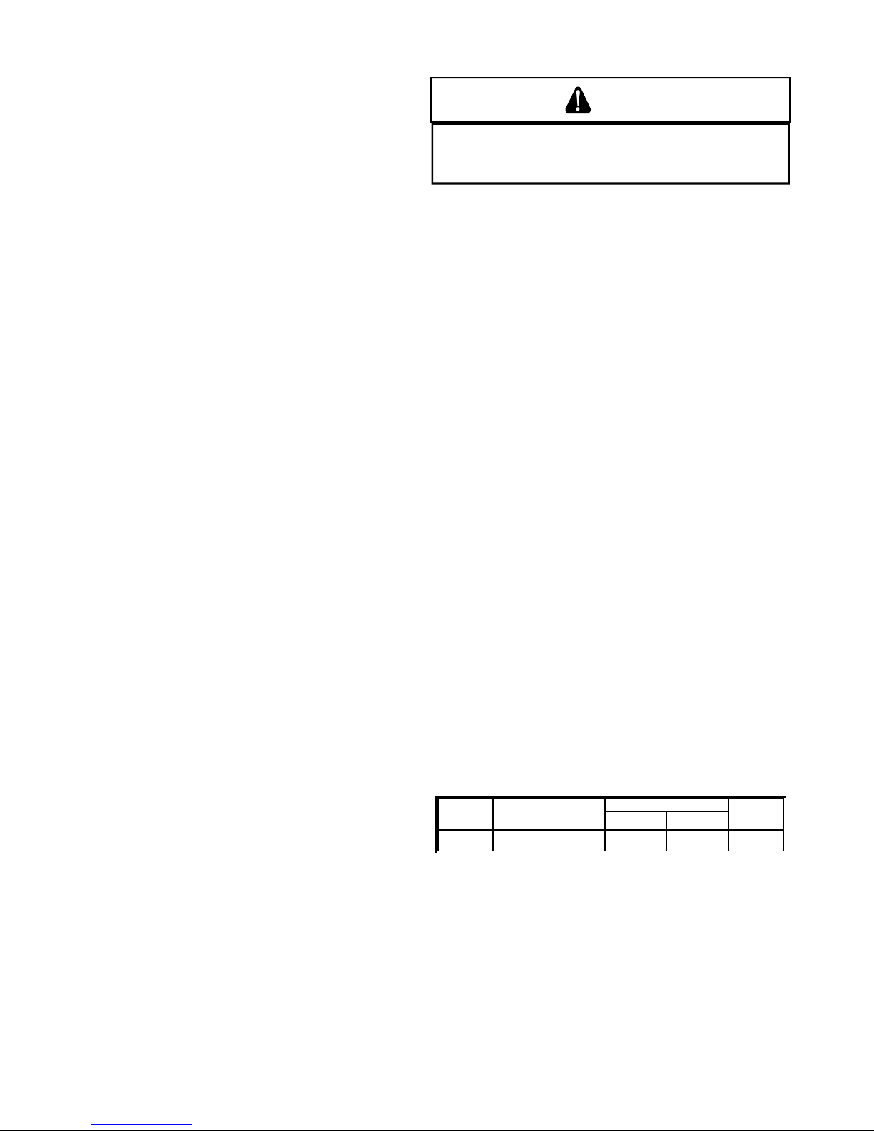
WARNING
O PREVENT POSSI BL E PE RSONAL I NJ URY OR DEAT H D UE TO ASPHYXIATI ON,
T
THI S FURNACE MUST BE
CATEGORY III VENTI N G.
Notes:
1. Category I Venting is venting at a non-positive pressure.
A furnace vented as Category I is considered a fan-assisted appliance and the vent system does not have to
be “gas tight.”
NOTE: Gas furnaces with induced draft blowers draw
products of combustion through a heat exchanger allowing,
in some instances, common venting with natural draft
appliances (i.e. water heaters).
All installations must be vented in accordance with National
Fuel Gas Code NFPA 54/ANSI Z223.1 - latest edition. In
Canada, the furnaces must be vented in accordance with
the National Standard of Canada, CAN/CSA B149.1 and
CAN/CSA B149.2 - latest editions and amendments.
NOTE: The vertical height of the Category I venting system
must be at least as great as the horizontal length of the
venting system.
2. Line voltage wiring can enter through the right or left side
of the furnace. Low voltage wiring can enter through the
right or left side of furnace.
3. Conversion kits for propane gas and high altitude natural
and propane gas operation are available. See High Altitude Derate chart for details.
Accessibility Clearances (Minimum)
Unobstructed front clearance of 24" for servicing is recommended.
MINIMUM CLEARANCE TO COMBUSTIBLE MATERIALS - INCHES
Sides TopRear Front*
1036 11
* 24" clearance for serviceability recommended.
** Single Wall Vent (SW) to be used only as a conncetor.
Refer to the venting tables outlined in the Installation Manual for
additional venting requirements.
Note: In all cases accessibility clearance shall take precedence over clearances from the enclosure where accessibility clearances are greater. All dimensions are given in inches.
ATEGORY I VENTED. DO NOT VENT USING
C
Vent
SW B
4
Page 5
PRODUCT DESIGN
A
D
Alcove Illustration
REAR
S
I
E
D
I
S
LCOVE
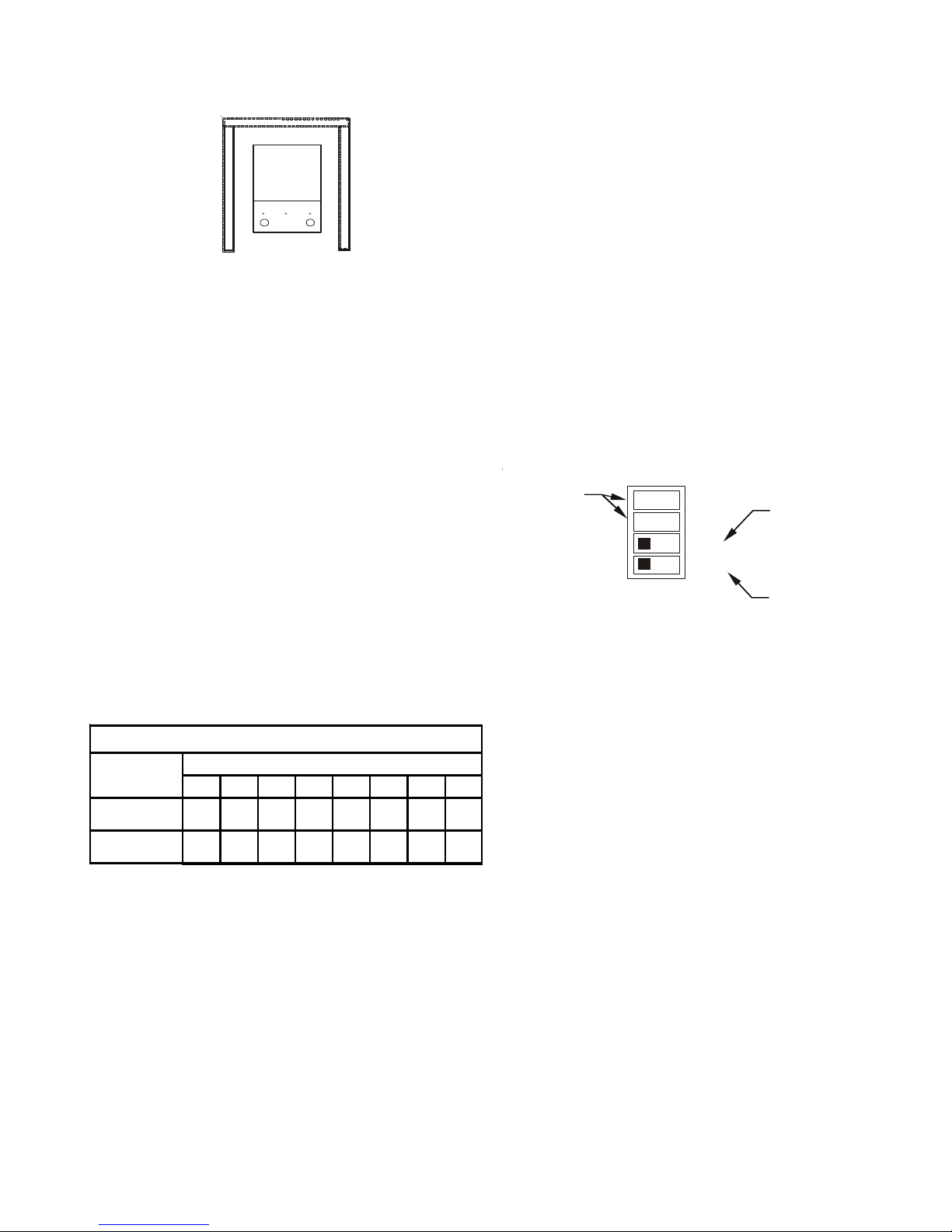
24" at front is required for servicing or cleaning.
Note: In all cases accessibility clearance shall take
precedence over clearances from the enclosure where
accessibility clearances are greater. All dimensions are
given in inches.
High Altitude Derate
When this furnace is installed at high altitude, the appropriate High Altitude orifice kit must be installed. This is required due to the natural reduction in the density of both the
gas fuel and combustion air as altitude increases. The kit
will provide the proper design certified input rate within the
specified altitude range.
High altitude kits are purchased according to the installation altitude and usage of either natural or propane gas. Refer
to the chart above for a tabular listing of appropriate altitude
ranges and corresponding manufacturer’s high altitude Natural Gas and Propane Gas kits. For a tabular listing of appropriate altitude ranges and corresponding manufacturer's High
Altitude Pressure Switch kits, refer to either the Pressure
Switch Trip Points & Usage Chart in this manual or the Accessory Charts in Service Instructions.
D
E
Single Stage Thermostat
A single-stage thermostat with only one heating stage may
be used to control this furnace. The application of a singlestage thermostat does not offer “true” thermostat-driven twostage operation, but provides a timed transition from low to
high fire. The furnace will run on low stage for a fixed period
of time before stepping up to high stage to satisfy the
thermostat’s call for heat. The delay period prior to stepping
up can be set at either a fixed 5 minute time delay or a load
based variable time between 1 and 12 minutes (AUTO mode).
If the AUTOmode is selected, the control averages the cycle
times of the previous three cycles and uses the average to
determine the time to transition from low stage to high stage.
To use a single-stage thermostat, turn off power to the furnace, move the thermostat selection DIP switch to the OFF
position. Set the desired transition time by setting the transition delay DIP switch to the desired ON/OFF position. Turn
power back on. Refer to the following figure.
Heat OFF Delay
DIP Switches
ON OFF
3
4
Thermostat
Stage Delay
S1
Move to the ON position
to select two-stage
thermostat or OFF to
select single stage
thermostat
Move to the ON position
to select A u to transition
delay or OFF for 5 minute
transition delay
INPUT PER BURNER - 22, 500 BTUH NATURAL GAS / 20,000 BTUH L.P.
ELEVATION ABOVE SEA-LEVEL (FEET)
2000 3000 4000 4500 5000 6000 7000 8000
US BUR NER
O RIF IC E
CANADA BURNER
O RIF IC E
HA-02 HIGH ALTITUDE CONVERSION KIT REQUIRE
Tabled data is based upon the furnace input being reduced for altitudes above sea level. U.S. 4% per 1,000 feet.
Canada 10% derate for 2,000-4,000 feet.
44/55 44/55 45/56 45/56 46/57 47/58 47/58
44/55 47/57
5
Page 6
COMPONENT IDENTIFICATION
2
Pressure Switch
3
Flue Pipe Connection
4
Induced Draft Blower
Gas Line
5
Entrance
6
Gas Valve
7
Rollout Limit
8
Junction Box
Tubular Heat Exchang er
1
躀
Wiring Harness
9
Grommet
Gas Manifold
Inshot Burner
Inductor
Transformer
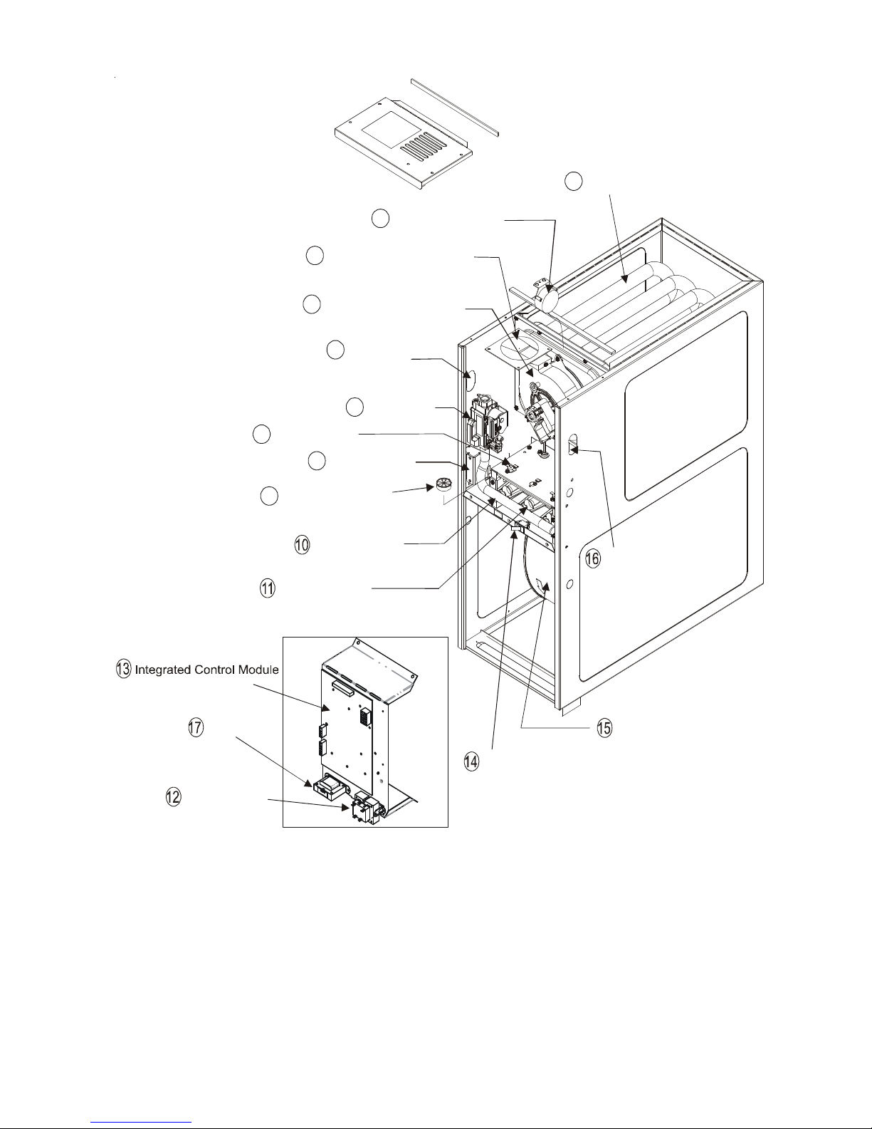
1 Tubular Heat Exchanger
2 Pressure Switch
3 Flue Pipe Connection
4 Induced Draft Blower
5 Gas Line Entrance
6 Gas Valve
7 Rollout Limit
8 Junction Box
9 Wiring Harness Grommet
Gas Line Entrance
(Alternate)
Circulator Blower
Blower Door
Interlock Switch
Upflow/Horizontal
10 Gas Manifold
11 Inshot Burner
12 Transformer
13 Integrated Control Module
14 Blower Door Interlock Swtich
15 Circulator Blower
16 Gas Line Entrance (Alternate)
17 Inductor
6
Page 7
COMPONENT IDENTIFICATION
Tubular Heat Exchanger
1
Inshot Burner
7
Rollout Limit
8
9
Transformer
Inductor
2
Pressure Switch
Gas Line
5
Entrance
Junction Box
Wiring Harness
Grommet
Blower Door
Interlock Switch
Gas Manifold
4
Induced Draft Blower
6
Gas Valve
Gas Line Entrance
(Alternate)
3
Flue Pipe Connection
Circulator Blowe r
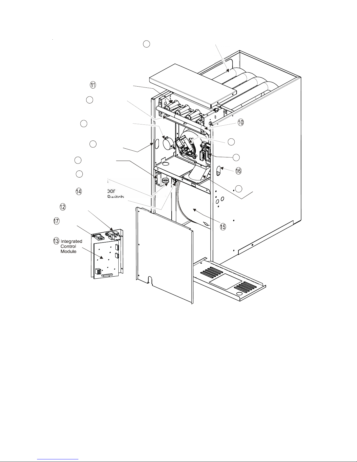
1 Tubular Heat Exchanger
2 Pressure Switch
3 Flue Pipe Connection
4 Induced Draft Blower
5 Gas Line Entrance
6 Gas Valve
7 Rollout Limit
8 Junction Box
9 Wiring Harness Grommet
10 Gas Manifold
11 Inshot Burner
12 Transformer
13 Integrated Control Module
14 Blower Door Interlock Swtich
15 Circulator Blower
16 Gas Line Entrance (Alternate)
17 Inductor
7
Page 8
PRODUCT DIMENSIONS
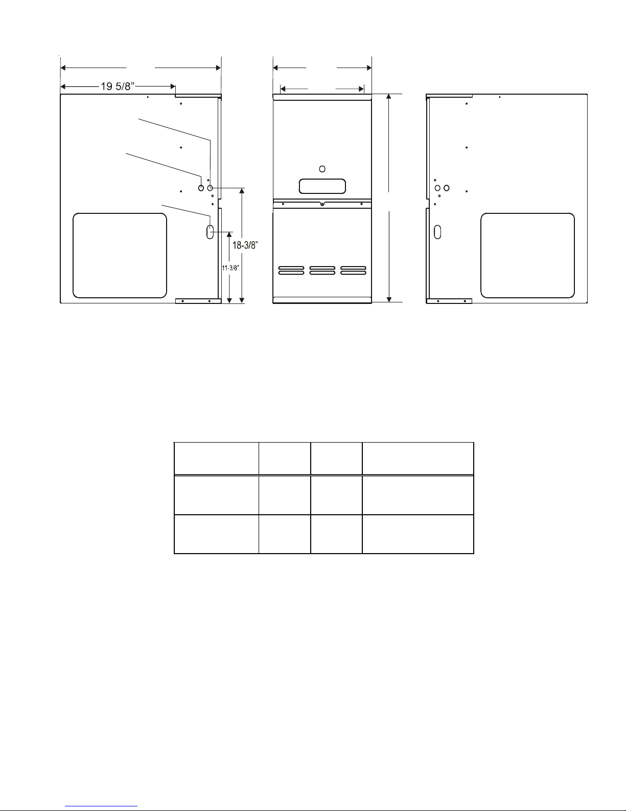
Alt. Gas Inlet
AMVC8/GMVC8_____X*
Alt. Gas Inlet
High Voltage Inlet
Low Voltage
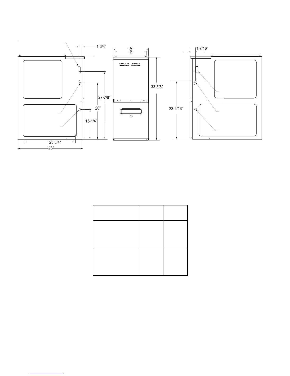
MODELS A B
AMVC80704BX **
GMVC80704BX**
17-1/2 16
Alt. High Voltage
Alt. LowVoltage
All dimensions ar e in inches.
8
AMVC80905CX**
AMVC81155CX**
GMVC80905CX **
GMVC81155CX **
21 19-1/2
Page 9
PRODUCT DIMENSIONS
A
28”
High Voltage
Electrical
Low Voltage
Electrical
ADVC8_____X*
B
Gas Inlet
33-3/8”
MODEL A B
ADV C80703 B X** 17 1/2 16 S B T17
NON-COMBUSTIBLE
FLOOR BASE
ADVC80905CX**
ADVC81155CX**
21 19 1/2 S B T21
All dim ens ions are in inc hes .
9
Page 10
PRODUCT DESIGN
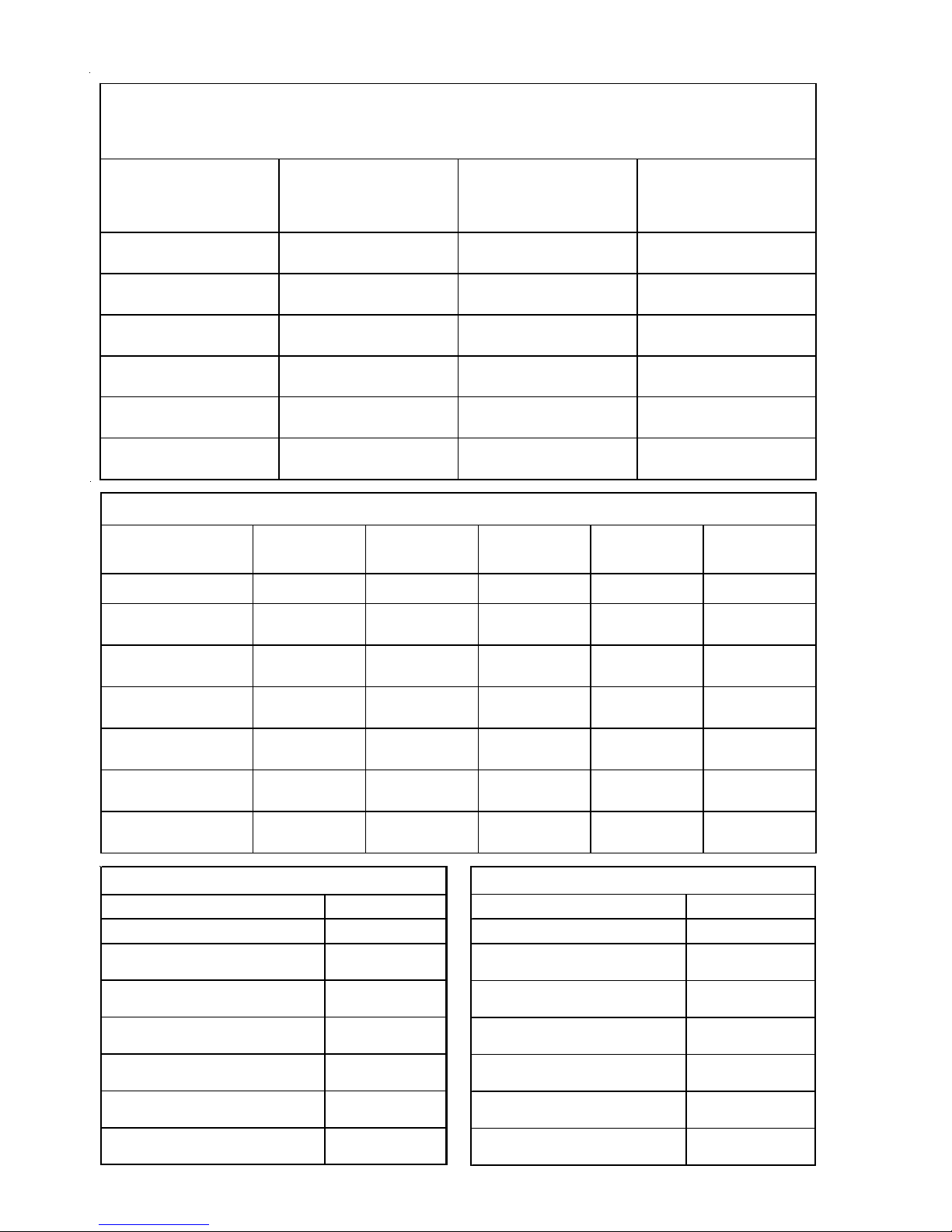
PRESSURE SWITCH TRIP POINT S
AND USAGE CHART
SQUARE NOSE
MODEL
AMVC800704BX**
GMVC8070 4BX**
AMVC80905CX**
GMVC80905CX**
AMVC81155CX**
GMVC81155CX**
ADVC80703BX**
ADVC80905CX**
ADVC81155CX**
TRIP POINT
ID BLOWER
PRESSURE SW ITCH -
LOW STAGE
-0.30 -0.65 0130F00049
-0.30 -0.60 0130F00050
-0.30 -0.60 0130F00050
-0.30 -0.55 B1370210
-0.30 -0.55 B1370210
-0.30 -0.55 B1370210
TRIP POINT
ID BLOWER
PRESSURE SWITCH -
HIGH STAGE
ID BLOWER
PRESSURE
SW ITCH
PART #
PRI M ARY LIM IT
Part Num b e r 0130M 00063 20162904 20162903 0130F 00067 0130F 00071
Op en Settin g (°F )
AMVC80704BX**
GMVC80704BX**
AMVC80905CX**
GMVC80905CX**
AMVC81155CX**
GMVC81155CX**
140 150 160 190 200
--- --- 1 --- ---
1 --- --- --- ---
--- 1 --- --- ---
ADVC80703BX**
ADVC80905CX**
ADVC81155CX**
RO LLO UT L IM IT S W ITC HES
Part Num ber 10123529
O p e n S e t t in g ( ° F )
AMVC80704BX**
GMVC80704BX**
AMVC80905CX**
GMVC80905CX**
AMVC81155CX**
GMVC81155CX**
ADVC80703BX**
ADVC80905CX**
ADVC81155CX**
--- --- --- 1 ---
--- --- --- 1 ---
--- --- --- --- 1
10
300
2
2
2
1
1
1
AUXILIARY LIMIT SW ITCHES
Part Num ber 0130F00038
O p e n S e tting (° F)
AMVC80704BX**
GMVC80704BX**
AMVC80905CX**
GMVC80905CX**
AMVC81155CX**
GMVC81155CX**
ADVC80703BX**
ADVC80905CX**
ADVC81155CX**
120
1
1
1
1
1
1
Page 11
PRODUCT DESIGN
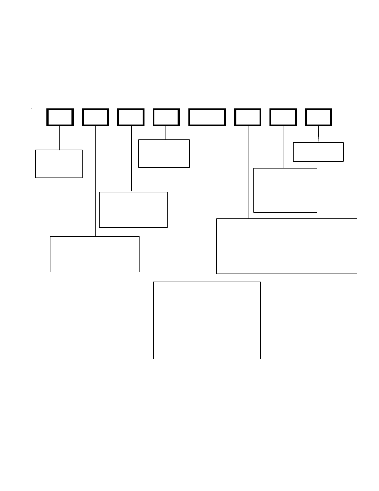
Coil Matches:
A large array of Amana® brand coils are available for use with the ADVC8 furnaces, in downflow applications, and with
AMVC8 and GMVC8 furnaces, in either upflow or horizontal applications. These coils are available in both cased and
uncased models (with the option of a field installed TXV expansion device). These 80%+ furnaces match up with the
existing Amana® brand coils as shown in the chart below.
Coil Matches (for Goodman® and Amana® Brand units using R22 and R-410A):
C A P F 1824 A 6 A
PRODUCT
TYPE:
C: Indoor Coil
APPLICATION
A: Up fl ow/D ownflow Coil
H: Hor izont al A C oil
S: Ho r izont al Slab Co il
EXPANSION
DEV ICE:
F: Flowrater
CAB INET F INIS H:
U: Unpainted
P: Pai nted
N: Unpai nted Ca se
N OMI NAL CAP ACI TY RA NGE
@ 13 SEER
18 24: 1 1/2 t o 2 Tons
30 30: 2 1/2 To ns
36 36: 3 Tons
36 42: 3 to 3 1/ 2 Tons
37 43: 3 to 3 1/ 2 Tons
48 60: 4 & 5 Tons
49 61: 4 & 5 Tons
REVISION
A: Revisio n
REFRIGERANT
CHARGE:
6 : R- 410A or R - 2 2
2: R- 22
4: R- 410a
NOMINAL WI DT H FO R GAS FURNACE
A: Fits 14 " F ur nace Cabine t
B: Fits 17 1/2" Fu r nace Cabi n et
C: Fits 21" Furnace Cabinet
D: Fits 24 1/2" Furnace Cabinet
N : Do es Not Apply (Horizonta l Slab Coils)
• All CAPF coils in B, C, & D widths have insulated blank off plates for use with one size smaller furnaces.
• All CAPF coils have a CAUF equivalent.
• All CHPF coils in B, C & D heights have an insulated Z bracket for use with one size smaller furnace.
• All proper coil combinations are subject to being ARI rated with a matched outdoor unit.
11
Page 12
PRODUCT DESIGN
Thermostats:
ComfortNet™ CTK01A* Thermostat Kit
Filters:
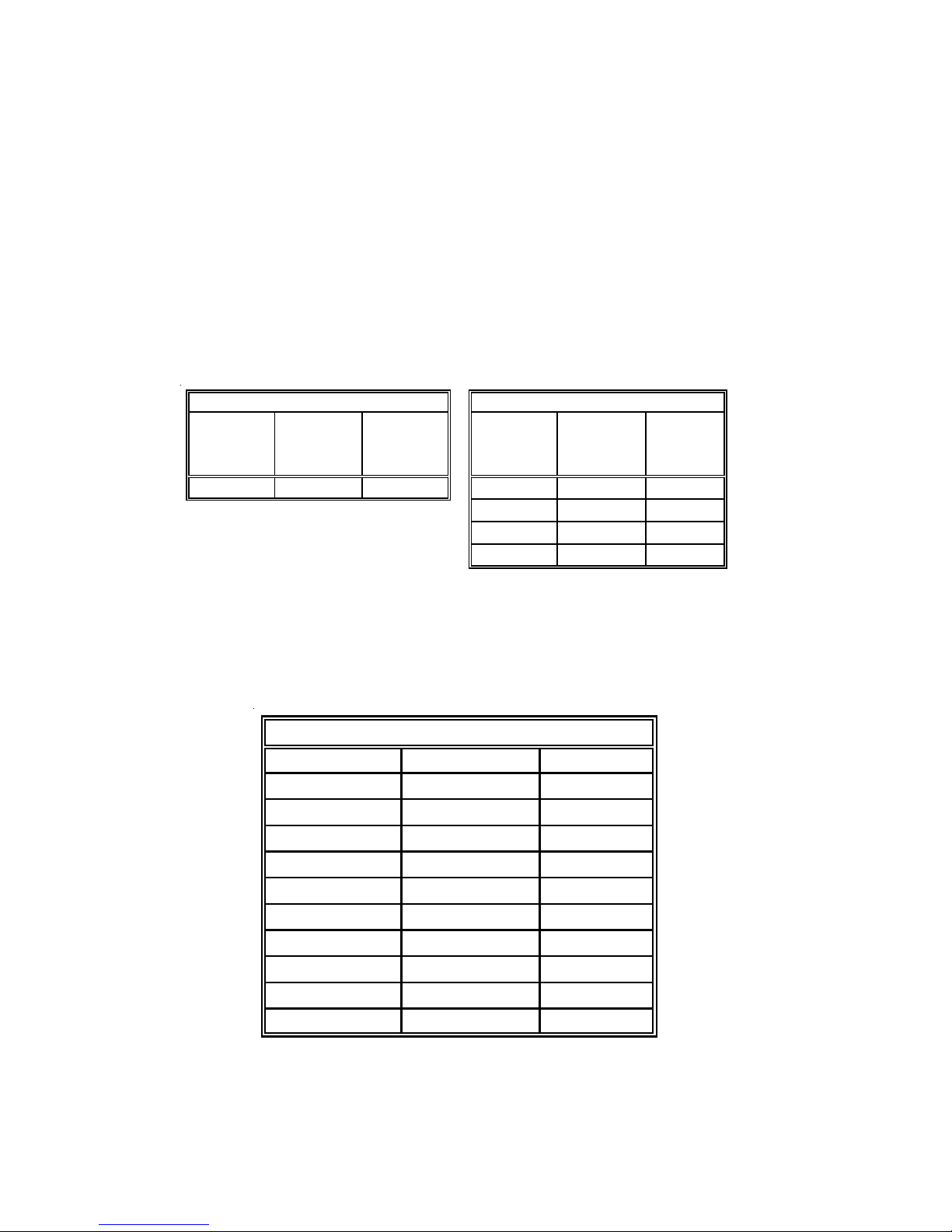
Filters are required with this furnace and must be provided by the installer. The filters used must comply with UL900 or
CAN/ULCS111 standards. Installing this furnace without filters will void the unit warranty
Upflow Filters
Return air filters may be installated at the furnace side and/or bottom return openings. The furnace bottom return opening
and side openings will accommodate the following filter sizes depending on cabinet size:
Side Re turn Open ing(s) Bottom Re turn Opening
Cabinet
Width
(in.)
Nominal
Filter Size
(in.)
Approx.
Flow A rea
2
(in
)
Cabinet
Width
(in.)
Nominal
Filter S iz e
(in.)
All 16 x 25 x 1 400 14 12 x 25 x 1 300
17-1/2 14 x 25 x 1 350
21 16 x 25 x 1 400
24-1/2 20 x 25 x 1 500
Approx.
Flow Area
(in2)
Refer to Minimum Filter Area tables to determine filter area requirement. NOTE: Filters can also be installed elsewhere in
the duct system such as a central return.
MINIMUM FILTER SIZES
FURNACE INPUT FILTER SIZE TYPE
45M
70M
90M
115M
140M
45M
70M
90M
115M
140M
PERMANENT NOMINAL 600 F.M. FACE VELOCITY
DISPOSABLE NOMINAL 300 F.M. FACE VELOCITY
160 in
241 in
320 in
400 in
370 in
320 in
483 in
640 in
800 in
738 in
2
2
2
2
2
2
2
2
2
2
permanent
permanent
permanent
permanent
permanent
disposable
disposable
disposable
disposable
disposable
12
Page 13
PRODUCT DESIGN
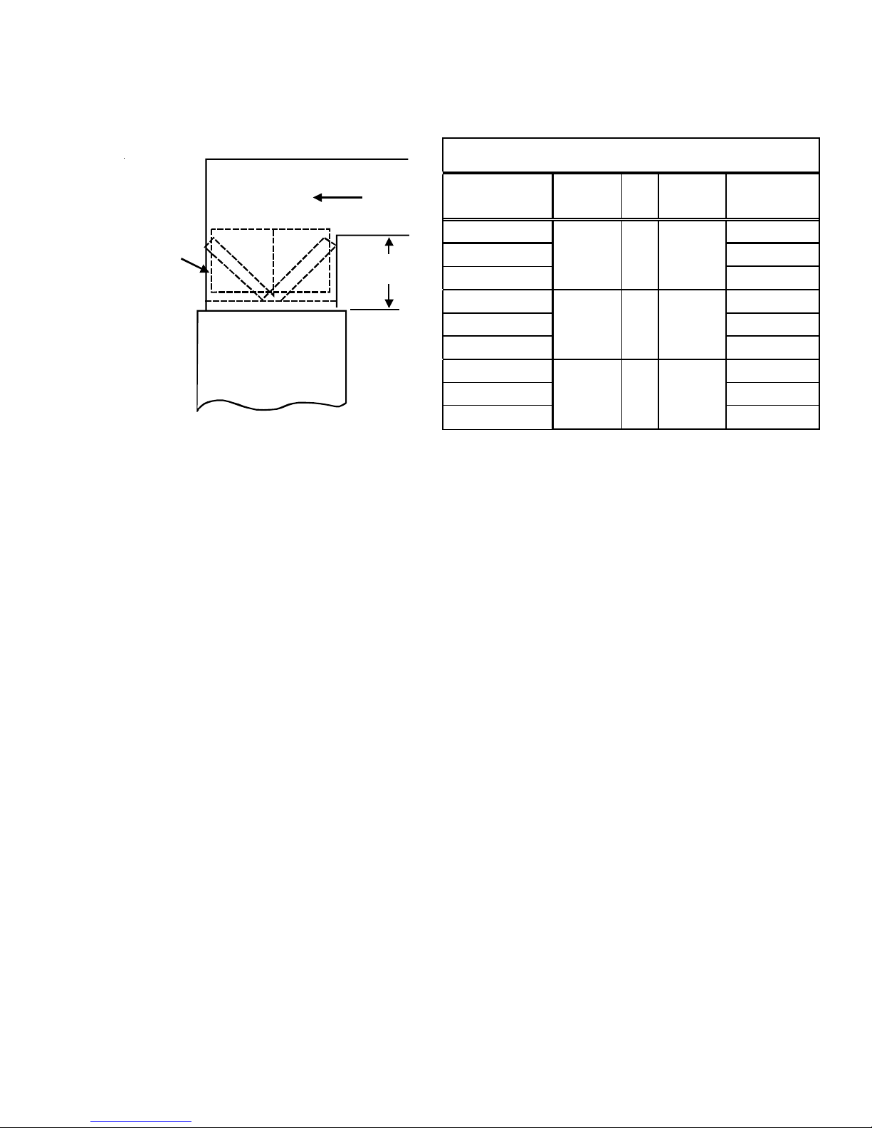
Downflow Filters
Return air filters may be installated at the at the downflow top return. A field supplied center filter support must be provided
by the installer in order to use the top return. The furnace will accommodate the following downflow top return filter sizes
depending on cabinet size:
Cou nte r flow Top Retu rn
Optional
Access
Door
Return Air
"A"
Min
Cabinet Width
17 1/2 14.2
21 13.0
24 1/2 11.3
17 1/2 19.7
21 18.8
24 1/2 17.7
17 1/2 25.0
21 24.3
24 1/2 23.4
Filter Area
2
(in
)
600 2 15 X 20 X 1
800 2 20 X 20 X 1
1 000 2 25 X 20 X 1
Qty
Filter Size
(in)
Dimension "A"
(in)
Refer to Minimum Filter Area tables to determine filter area requirement. NOTE: Filters can also be installed elsewhere
in the duct system such as a central return.
13
Page 14
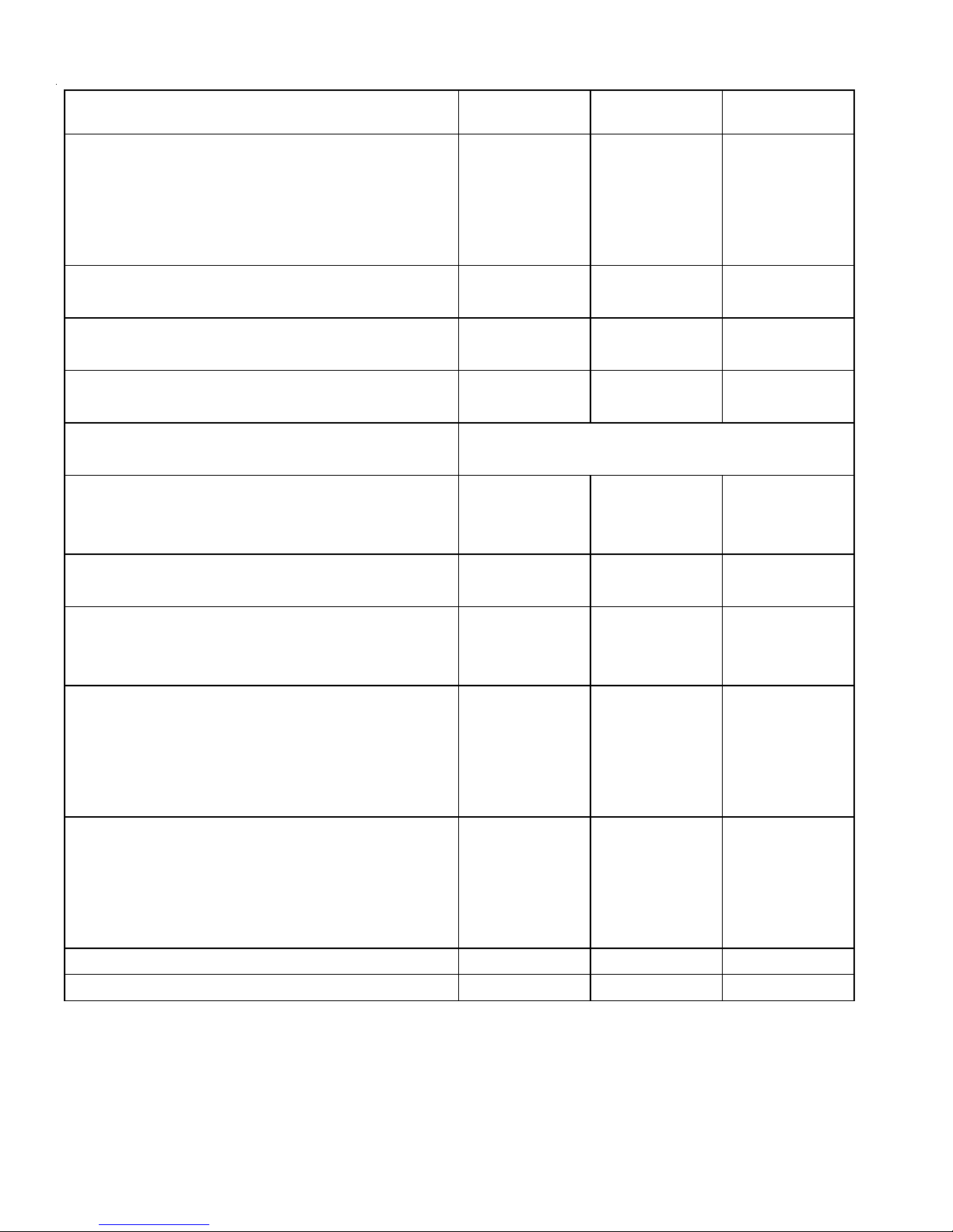
FURNACE SPECIFICATIONS
AMVC8
MODEL
Bt uh Input (US) High Fire 70,000 90,000 115,000
Out put (US) High F ire 5 7,000 74,000 93,000
Bt uh Input (US) Low Fire 49,000 63,000 80,000
Out put (US) Low F ire 39,200 50,400 64,000
A. F.U .E . 80% 80% 80%
Rated Ex ternal S tatic (" w.c.) .10 - .50 .10 - .50 .10 - .50
Temperature Rise (°F) 20 - 50 20 - 50 25 - 55
High S tage P ress ure Sw itch Trip Point (" w.c .) -0.65 -0.60 -0.60
Low S tage P ress ure S witch Trip P oint (" w.c .) -0.30 -0.30 -0.30
Blowe r W heel (D" x W") 10 x 8 10 x 10 10 x 10
Blowe r Horsepower 3/4 3/4 3/4
Blowe r Speeds
Max CFM @ 0.5 E.S.P.
Pow er Supply 115-60-1 115-60-1 115-60-1
M inimum C ircuit A m pac ity (M CA ) 12.1 12.1 12.1
M ax imu m Overc urrent Device 15 15 15
Trans former (VA) 40 40 40
Heat Anticipator (A m ps) 0.7 0.7 0.7
Prim ary Lim it S etting (°F) 160 140 150
A ux iliary Limit S et ting (°F) 120 120 120
Rollout Lim it Set ting (°F) 300 300 300
Fan Delay On Heating 30 secs. 30 secs. 30 secs.
Off Heating * 150 secs . 150 s ecs . 150 s ecs .
Fan Delay On Cooling 5 secs. 5 secs. 5 secs.
Off Cooling 45 secs. 45 secs. 45 secs.
Fan Delay On - Fan Only 5 secs. 5 secs. 5 secs.
Gas S upply P ress ure (Natural/Propane) (" w.c .) 7 / 11 7 / 11 7 / 11
M anifold P ress ure (Natural/Propane) High St age (" w.c .) 3.5 / 10 3.5 / 10 3.5 /10
M anifold P ress ure (Natural/Propane) Low S tage ("w.c .) 1. 9 / 6.0 1.9 / 6. 0 1.9 / 6.0
Orific e S ize (Natural/Propane) #43 / #55 #43 / #5 5 #43 / #55
Number of B urners 3 4 5
Vent Connect or Diameter (inches) 4 4 4
Shipping W eight (lbs.) 138 156 156
AM V C80070 4BX ** AMV C80905C X ** AM V C8 1155CX **
Refer t o airflow ch arts in this m anual.
* Off Heating - This fan delay timing is adjustable (90, 120, 150 or 180 seconds), 150 seconds as shipped.
1. These furnaces are manufactured for natural gas operation. Optional Kits are available for conversion to propane gas operation.
2. For elevations above 2000 ft. the rating should be reduced by 4% for each 1000 ft. above sea level. The furnace must not be derated, orifice
changes should only be made if necessary for altitude.
3. The total heat loss from the structure as expressed in TOTAL BTU/HR must be calculated by the manufactures method in accordance with the
"A.S.H.R.A.E. GUIDE" or "MANUAL J-LOAD CALCULATIONS" published by the AIR CONDITIONING CONTRACTORS OF AMERICA. The total
heat loss calculated should be equal to or less than the heating capacity. Output based on D.O.E. test procedures, steady state efficiency times
output.
4. Minimum Circuit Ampacity calculated as: (1.25 x Circulator Blower Amps) + I.D. Blower Amps.
14
Page 15
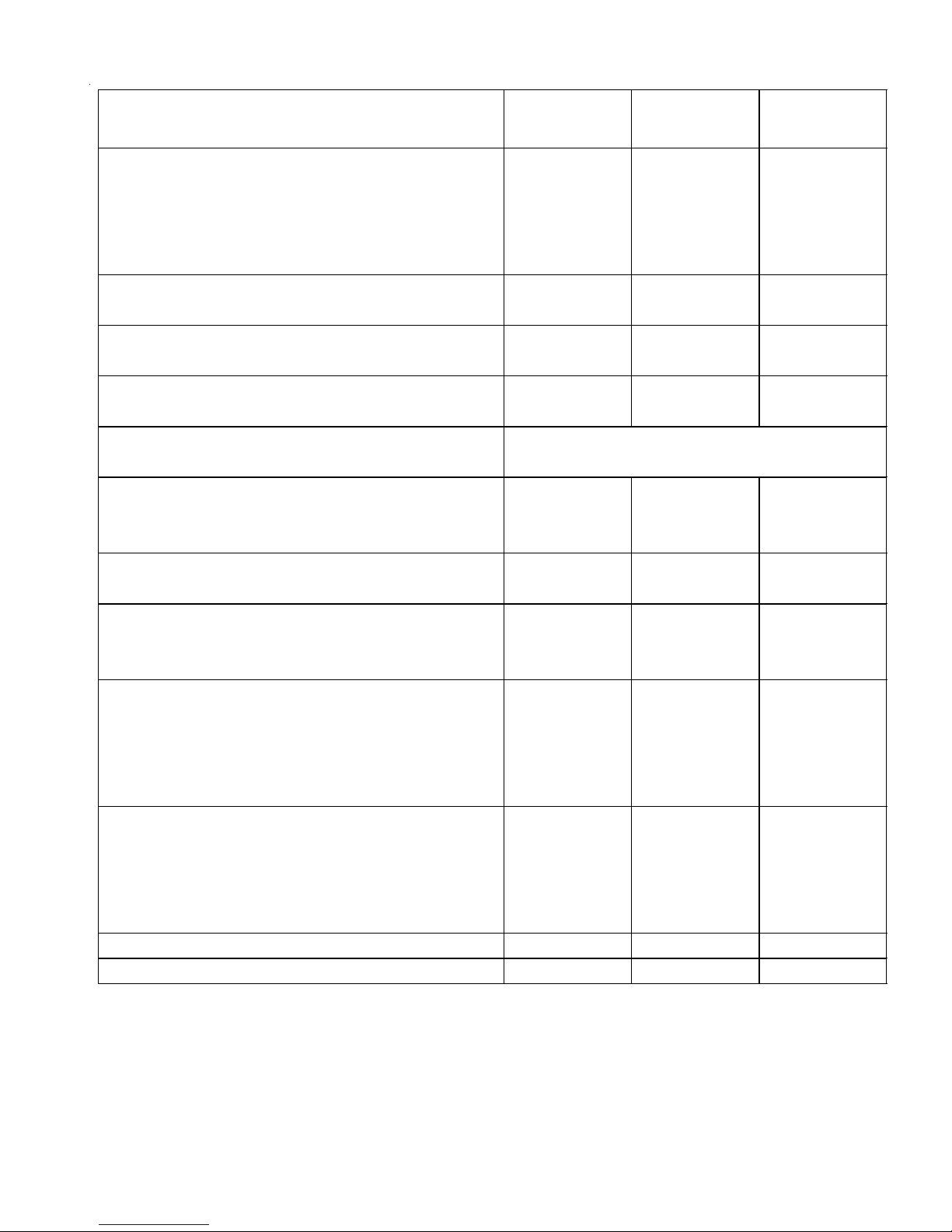
FURNACE SPECIFICATIONS
GMVC8
MODEL
Btuh Input (US) High Fire 70,000 90,000 115,000
Output (US ) High Fire 57,000 74,000 93,0 00
Btuh Input (US) Low Fire 49,000 63,000 80,000
Output (US ) Low Fire 39,200 50,400 64,000
A.F .U.E . 80% 80% 80%
Rated E x ternal Static (" w.c.) .10 - .50 .10 - .50 .10 - .50
Temperature Rise (°F) 20 - 50 20 - 50 25 - 55
High S tage P ressure S witch Trip P oint (" w.c.) -0.65 -0.60 -0.60
Low Stage Pressure Switch Trip Point (" w.c.) -0.30 -0.30 -0.30
B lower W heel (D" x W ") 10 x 8 10 x 10 10 x 10
Blower Hors epower 3/4 3/4 3/4
B lower Speeds
Max CFM @ 0.5 E.S.P.
P ower Supply 115-60-1 115-60-1 115-60-1
M inimum Circuit A m pacity (M C A ) 12.1 12.1 12.1
M axim um O vercurrent Device 15 15 15
Trans form er (VA ) 40 40 40
Heat A nticipator (A m ps ) 0.7 0.7 0.7
P rim ary Lim it Setting (°F) 160 140 150
A uxiliary Limit S etting (°F ) 120 120 120
Rollout Limit S etting (°F) 300 300 300
Fan Delay On Heating 30 secs. 30 secs. 30 secs.
Off Heating * 150 sec s . 150 s ecs . 150 se cs .
Fan Delay On Cooling 5 secs. 5 secs. 5 secs.
Off Cooling 45 sec s . 45 sec s. 4 5 sec s.
Fan Delay On - Fan Only 5 secs. 5 secs. 5 secs.
Gas S upply P ress ure (Natural/P ropane) (" w.c .) 7 / 11 7 / 11 7 / 11
M anifold P ressure (Natural/P ropane) High Stage (" w.c.) 3.5 / 10 3.5 / 10 3.5 /10
M anifold P ressure (Natural/P ropane) Low Stage ("w.c.) 1.9 / 6.0 1.9 / 6.0 1.9 / 6.0
Orifice Size (Natural/Propane) #43 / #55 #43 / #55 #43 / #55
Num ber of Burners 3 4 5
V ent Connec tor Diameter (inches) 4 4 4
Shipping W eight (lbs.) 138 156 156
GMVC 80704BX ** GM V C 80905CX ** GM V C1155 CX **
Refer to airflow charts in this m anua l.
* Off Heating - This fan delay timing is adjustable (90, 120, 150 or 180 seconds ), 150 seconds as shipped.
1. These furnaces are manufactured for natural gas operation. Optional Kits are available for conversion to propane gas operation.
2. For elevations above 2000 ft. the rating should be reduced by 4% for each 1000 ft. above sea level. The furnace must not be derated, orifice
changes should only be made if necessary for altitude.
3. The total heat loss from the structure as expressed in TOTAL BTU/HR must be calculated by the manufactures method in accordance with the
"A.S.H.R.A.E. GUIDE" or "MANUAL J-LOAD CALCULATIONS" published by the AIR CONDITIONING CONTRACTORS OF AMERICA. The total
heat loss calculated should be equal to or less than the heating capacity. Output based on D.O.E. test procedures, steady state efficiency times
output.
4. Minimum Circuit Ampacity calculated as: (1.25 x Circulator Blower Amps) + I.D. Blower Amps.
15
Page 16
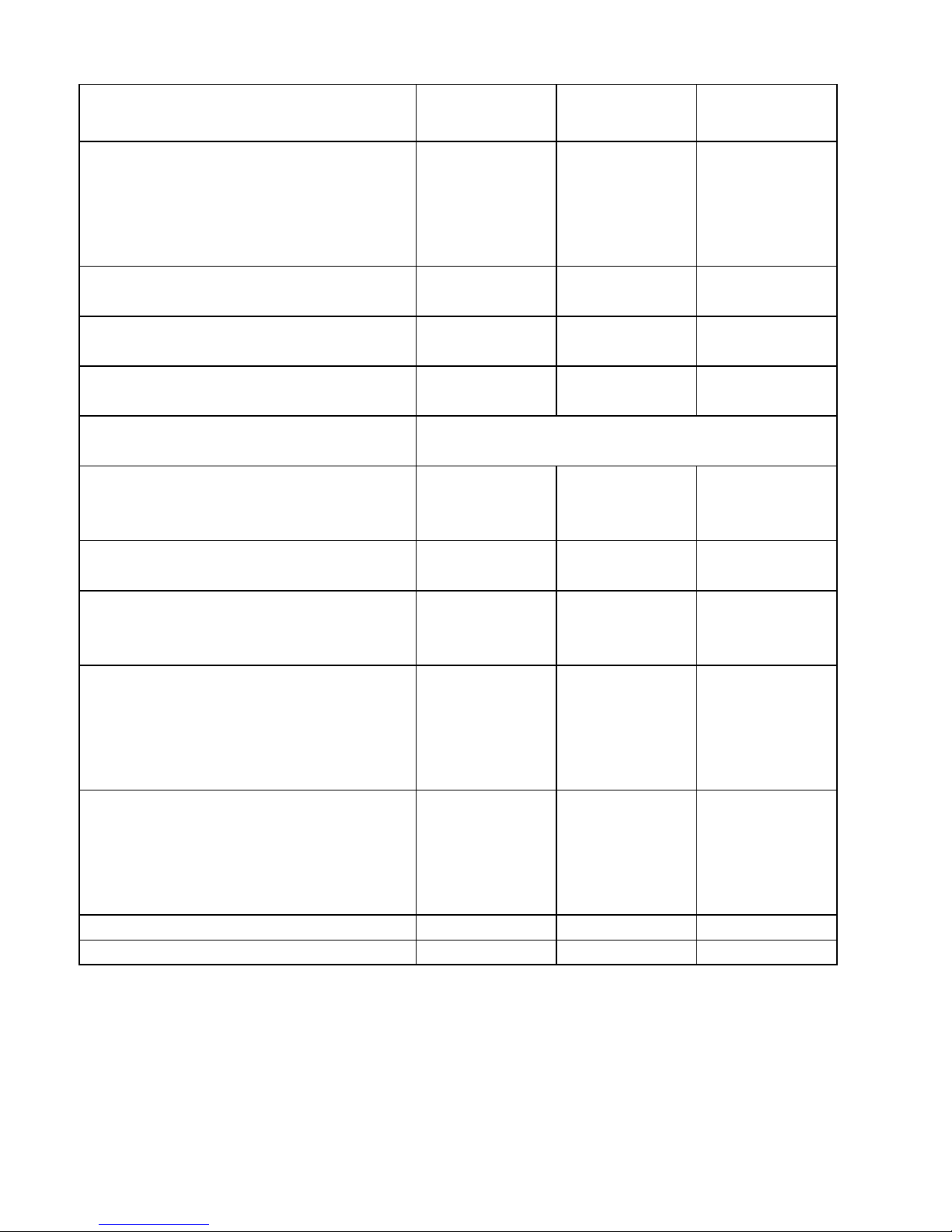
FURNACE SPECIFICATIONS
ADVC8
MODEL
Bt uh Input (US ) Hig h F i re 70,000 90,000 115, 000
Output (US ) High Fire 56,000 72,000 92,000
Bt uh Input (US) Low Fi re 51,000 63,000 80,500
Output (US ) Low Fire 40,800 50,400 64,400
A.F . U.E . 80% 80% 80 %
Rated E x t ernal S t at ic (" w. c . ) .10 - .50 .10 - .50 . 10 - . 50
Temperature Ris e (°F) 30 - 60 35 - 65 35 - 65
High St age P res sure S wit c h Trip Poi nt (" w. c . ) -0.55 -0.55 -0. 55
Low St age P res s ure S wit c h Trip Point (" w. c . ) -0.30 -0.30 -0. 30
Blower Wheel (D" x W" ) 10 x 8 10 x 10 10 x 10
Blower Hors epower 3/ 4 3/4 3/4
Blower S peeds
Max CFM @ 0.5 E.S.P.
Power S upply 115-60-1 115-60-1 115 -60-1
Minimum Circuit Ampacity (MCA) 12.1 12.1 12.1
Max im um O vercurrent Device 15 15 15
Transformer (VA) 40 40 40
Heat A ntic i pat or (Amp s ) 0.7 0.7 0.7
Prim ary Lim i t S e t ti ng (°F) 190 1 90 200
Aux il iary Li m it S et t ing (°F) 120 120 120
Rollout Li m it S et t ing (°F) 300 300 300
Fan Delay On Heating 30 secs. 30 secs. 30 secs.
Off Heating * 150 secs . 150 secs. 150 secs.
Fan Delay On Cooling 5 secs. 5 secs. 5 secs.
Off Cooling 45 secs. 45 secs. 45 secs.
Fan Delay On - Fan Only 5 secs. 5 secs. 5 secs.
Gas Supply Pres s ure (Natural / P ropane) (" w. c . ) 7 / 11 7 / 11 7 / 11
Manifold P res s ure (Nat ural/ P ropane) High St age (" w. c . ) 3.5 / 10 3.5 /10 3.5 /1 0
Manifold P res s ure (Natu ral/ P ropane) Low S t age ("w. c . ) 1. 9 / 6. 0 1.9 / 6. 0 1. 9 / 6. 0
Orifice S i z e (Natu ral/Propane) #43 / #55 #43 / #55 #43 / #55
Number of Burners 3 4 5
Vent Connec t or Diam et er (inc hes ) 4 4 4
Shipping Weight (lbs. ) 112 124 130
ADVC80703BX** ADVC80905CX** ADVC81155CX**
Refer to airflow charts in this manual.
* Of f Heating - This fan delay timing is adjustable (90, 120, 150 or 180 seconds), 150 seconds as shipped.
1. These furnaces are manufactured for natural gas operation. Optional Kits are available for conversion to propane gas operation.
2. For elevations above 2000 ft. the rating should be reduced by 4% for each 1000 ft. above sea level. The furnace must not be derated, orifice
changes should only be made if necessary for altitude.
3. The total heat loss from the structure as expressed in TOTAL BTU/HR must be calculated by the manufactures method in accordance with the
"A.S.H.R.A.E. GUIDE" or "MANUAL J-LOAD CALCULATIONS" published by the AIR CONDITIONING CONTRACTORS OF AMERICA. The total
heat loss calculated should be equal to or less than the heating capacity. Output based on D.O.E. test procedures, steady state efficiency times
output.
4. Minimum Circuit Ampacity calculated as: (1.25 x Circulator Blower Amps) + I.D. Blower Amps.
16
Page 17
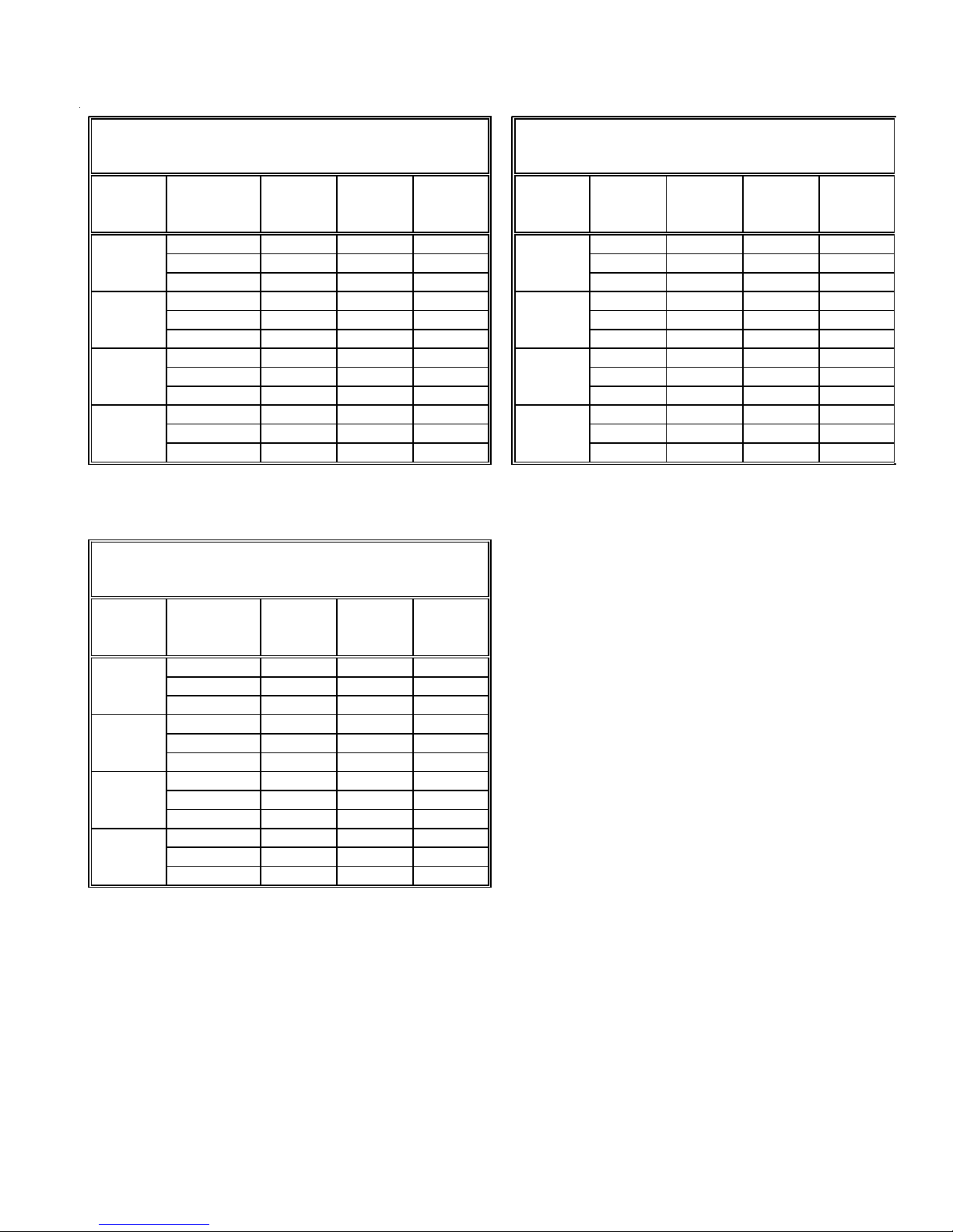
BLOWER PERFORMANCE SPECIFICATIONS
(
)
(
)
AMVC8/GMVC8 Heating Speed Charts
Heating
Speed
Tap
A
B
C
D
Heating
Speed
Tap
A
B
C
D
AMVC80704BX **
GM V C 80704BX **
Rise Ra nge : 20° - 50°F
Low -
Adjust Tap
Minus (-) 790 1125 46 M inus (-) 945 1350 49
Normal 875 1250 41 Normal 1050 1500 44
Plus (+) 960 1375 38 Plus (+) 1155 1650 40
Minus (-) 850 1215 43 M inus (-) 1010 1440 46
Normal 945 1350 38 Normal 1120 1600 42
Plus (+) 1040 1485 35 P lus (+) 1230 1760 38
Minus (-) 915 1305 40 M inus (-) 1070 1530 44
Normal 1015 1450 36 Normal 1190 1700 39
Plus (+) 1115 1595 33 P lus (+) 1310 1870 36
Minus (-) 975 1395 37 M inus (-) 1135 1620 41
Normal 1085 1550 33 Normal 1260 1800 37
Plus (+) 1195 1705 30 P lus (+) 1385 1980 34
AMVC81155CX **
GM V C 81155CX **
(Ri se Ran g e : 2 5° - 5 5°F )
Adjust Tap
Minus (-) 1090 1555 55
Normal 1210 1725 49
Plus (+) 1330 1900 45
Minus (-) 1105 1575 54
Normal 1225 1750 49
Plus (+) 1350 1925 44
Minus (-) 1120 1600 53
Normal 1245 1775 48
Plus (+) 1370 1955 44
Minus (-) 1135 1620 53
Normal 1260 1800 47
Plus (+) 1385 1980 43
Stage
CFM
Low -
Stage
CFM
High-
Stage
CFM
High-
Stage
CFM
Rise (°F)
Rise (°F)
He a ting
Speed
Tap
A
B
C
D
AM V C80905CX **
GM VC80905CX **
Rise Range : 20° - 50°F
Adjust
Tap
Low -
Stage
CFM
High -
Stage
CFM
Rise (°F)
1. Units are shipped without filter(s). CFM in chart is without filter(s).
2. All furnaces shipped with heating speed set at "B" and cooling speed set at "D". Installer should adjust blower speed
as needed. The first task is to determine the proper aiflow for the cooling system.
3. For most cooling applications, about 400 CFM per ton is desirable.
4. The chart is for information only. For satisfactory operation, external static pressure not to exceed value shown on
rating plate.
5. Do not operate above 0.5" w.c. ESP in heating mode. Operating between 0.5" w.c. and 0.8" w.c. is tabulated for cooling
purposes only.
6. * Motor CFM maximum.
17
Page 18
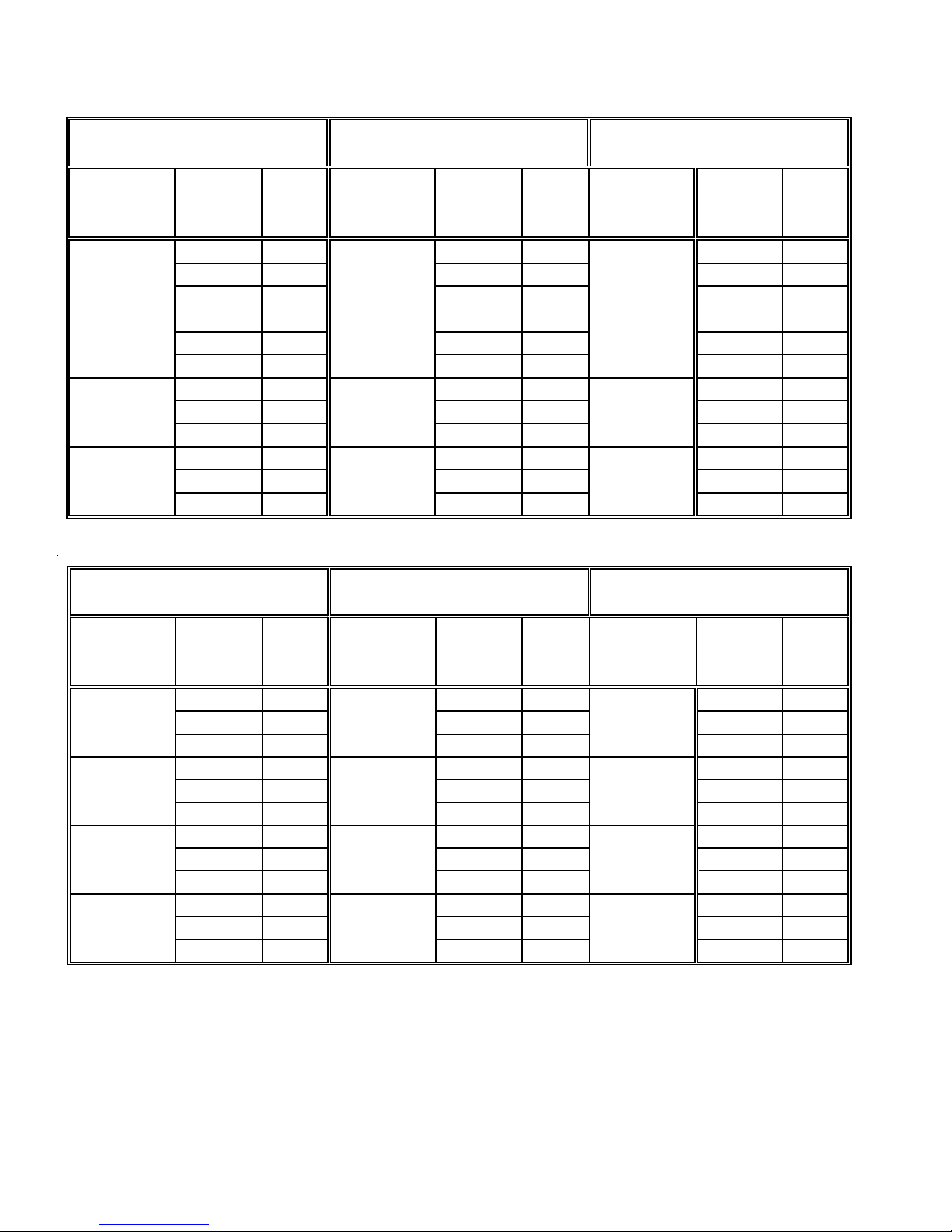
BLOWER PERFORMANCE SPECIFICATIONS
AMVC8/GMVC8
AMVC80704 BX**
GMVC80704BX**
Cooling
Speed Tap
High (Single) Stage Cooling Speed Charts
AMVC80905CX**
GMVC80905CX**
Adj ust
Tap
CFM
Cooling
1
Spe e d Tap
Adj ust
Tap
CFM
Minus (-) 540 Minus (-) 720 Minus (-) 720
A
Normal 600 Normal 800 Normal 800
A
Plus (+ ) 660 Plus (+ ) 880 Plus (+ ) 880
Minus (-) 720 Minus (-) 990 Minus (-) 990
B
Normal 800 Normal 1100 Normal 1100
B
Pl us (+ ) 880 P lus (+ ) 1210 Pl us (+ ) 1210
Mi nus (-) 990 M inus (-) 1260 Mi nus (-) 1260
C
Normal 1100 Normal 1400 Normal 1400
C
Pl us (+ ) 1210 Pl us (+ ) 1540 Pl us (+ ) 1540
Mi nus (-) 1260 Minu s (-) 1620 Minus (-) 16 20
D
Normal 140 0 Normal 1 800 Norm al 18 00
D
Pl us (+ ) 1540 Pl us (+ ) 1980 Pl us (+ ) 2,000 *
AMVC8/GMVC8 Low Stage Cooling Speed Charts
Cooling
1
Speed Tap
A
B
C
D
AMVC81155CX**
GMVC81155CX**
Adjust
Tap
CFM
1
AM VC80704 BX**
GMV C807 04 BX**
Cooling
Speed Tap
Adj u st
Tap
CFM
1
Minus (-) 351 Minus (-) 468 Minus (-) 468
A
Normal 390 Normal 520 Normal 520
Pl us (+ ) 429 Plus (+ ) 572 Pl us (+ ) 572
Minus (-) 468 Minus (-) 644 Minus (-) 644
B
Normal 520 Normal 715 Normal 715
Pl us (+ ) 572 Plus (+ ) 787 Pl us (+ ) 787
Minus (-) 644 Minus (-) 819 Minus (-) 819
C
Normal 715 Normal 910 Normal 910
Pl us (+ ) 787 Plus (+ ) 1001 P l us (+ ) 1001
Mi nus (-) 819 M inus (-) 105 3 M i nus (-) 1053
Normal 910 Normal 117 0 Normal 1170
Pl us (+ ) 1001 P lus (+ ) 1287 P l us (+ ) 1287
1. Units are shipped without filter(s). CFM in chart is without filter(s).
2. All furnaces shipped with heating speed set at "B" and cooling speed set at "D". Installer should adjust blower speed
as needed. The first task is to determine the proper aiflow for the cooling system.
3. For most cooling applications, about 400 CFM per ton is desirable.
4. The chart is for information only. For satisfactory operation, external static pressure not to exceed value shown on
rating plate.
5. Do not operate above 0.5" w.c. ESP in heating mode. Operating between 0.5" w.c. and 0.8" w.c. is tabulated for cooling
purposes only.
6. * Motor CFM maximum.
18
AMVC80905CX* *
GMVC80905CX**
Cooling
Speed Tap
A
B
Adjust
Tap
CFM
1
Speed Tap
AMVC8115 5CX**
GMVC81155CX**
Cooling
A
B
Adjust
Tap
CFM
CC
D
DD
1
Page 19
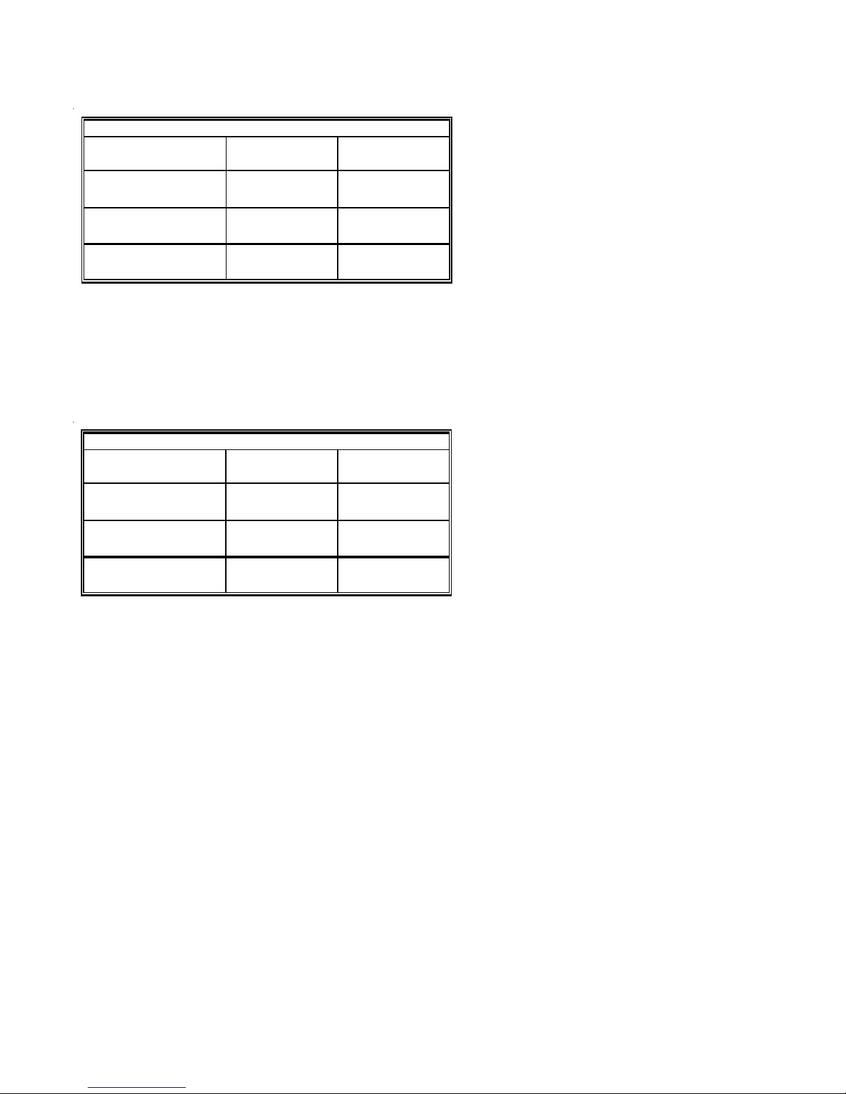
BLOWER PERFORMANCE SPECIFICATIONS
p
p
AMVC8/GMVC8
Continuous Fan Speed Chart
Continous Fan Speeds
Model
AMVC800704BX**
GMVC80704BX**
AMVC80905CX**
GMVC80905CX**
AMVC81155CX**
GMVC81155CX**
1
Continuous fan speed is 30% of furnace maximum CFM
2
Three continuous fan speeds are pos sible with the
Furnace
Ma x imu m CFM
1760 530
2000 600
2000 600
Co ntinu ous Fan
eed
1,2
S
C TK01AA thermostat : 30%, 50%, and 70% of furnace
maximum C FM
ADVC8 Continuous Fan Speed Chart
Continous Fan Speeds
Model
Furnace
Ma x imu m CFM
Co ntinu ous Fan
1,2
S
eed
ADVC80703BX** 1760 530
ADVC80905CX** 2000 600
ADVC81155CX** 2000 600
1
Continuous fan speed is 30% of furnace maximum CFM
2
Three continuous fan speeds are pos sible with the
C TK01AA thermostat : 30%, 50%, and 70% of furnace
maximum C FM
1. Units are shipped without filter(s). CFM in chart is without filter(s).
2. All furnaces shipped with heating speed set at "B" and cooling speed set at "D". Installer should adjust blower speed
as needed. The first task is to determine the proper aiflow for the cooling system.
3. For most cooling applications, about 400 CFM per ton is desirable.
4. The chart is for information only. For satisfactory operation, external static pressure not to exceed value shown on
rating plate.
5. Do not operate above 0.5" w.c. ESP in heating mode. Operating between 0.5" w.c. and 0.8" w.c. is tabulated for cooling
purposes only.
6. * Motor CFM maximum.
19
Page 20
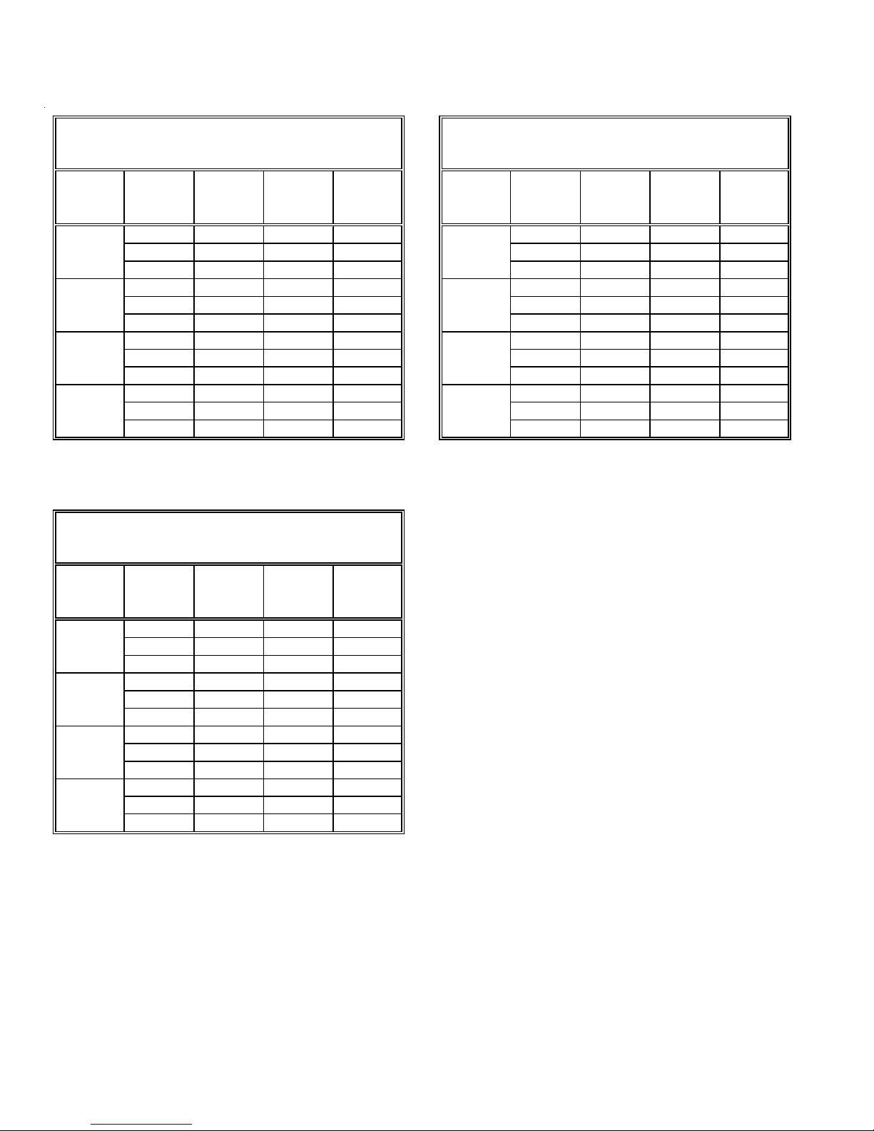
BLOWER PERFORMANCE SPECIFICATIONS
ADVC8 Heating Speed Chart
ADVC80703BX **
(Rise Ran g e : 30° - 60°F)
Heating
Speed
Tap
AA
BB
CC
DD
Adju st
Tap
Minus (-) 660 945 55 Minus (-) 850 1215 55
Normal 735 1050 49 Normal 945 1350 49
Plus (+ ) 810 1155 45 Plus (+ ) 1040 1485 45
Minus (-) 725 1035 50 M inus (-) 915 1305 51
Normal 805 1150 45 Normal 1015 1450 46
Plus (+ ) 885 1265 41 Plus (+ ) 1115 1595 42
Minus (-) 790 1125 46 M inus (-) 975 1395 48
Normal 875 1250 41 Normal 1085 1550 43
Plus (+ ) 960 1375 38 Plus (+ ) 1195 1705 39
Minus (-) 850 1215 43 M inus (-) 1040 1485 45
Normal 945 1350 38 Normal 1155 1650 40
Plus (+ ) 1040 1485 35 P lus (+) 1270 1815 37
(Rise Ran g e : 35° - 65°F)
Low -
Stage
CFM
ADVC81155CX **
High-
Stage
CFM
Rise (°F)
Heating
Speed
Tap
ADVC80905CX **
(Rise Ran g e : 30° - 60°F)
Adju st
Tap
Low-
Stage
CFM
High-
Stage
CFM
Rise (°F)
Heating
Speed
Tap
A
B
C
D
Adju st
Tap
Minus (-) 975 1395 61
Normal 1085 1550 55
Plus (+ ) 1195 1705 50
Minus (-) 1040 1485 57
Normal 1155 1650 52
Plus (+ ) 1270 1815 47
Minus (-) 1105 1575 54
Normal 1225 1750 49
Plus (+ ) 1350 1925 44
Minus (-) 1135 1620 53
Normal 1260 1800 47
Plus (+ ) 1385 1980 43
Low -
Stage
CFM
High-
Stage
CFM
1. Units are shipped without filter(s). CFM in chart is without filter(s).
2. All furnaces shipped with heating speed set at "B" and cooling speed set at "D". Installer should adjust blower speed
as needed. The first task is to determine the proper aiflow for the cooling system.
3. For most cooling applications, about 400 CFM per ton is desirable.
4. The chart is for information only. For satisfactory operation, external static pressure not to exceed value shown on
rating plate.
5. Do not operate above 0.5" w.c. ESP in heating mode. Operating between 0.5" w.c. and 0.8" w.c. is tabulated for cooling
purposes only.
6. * Motor CFM maximum.
20
Rise (°F)
Page 21
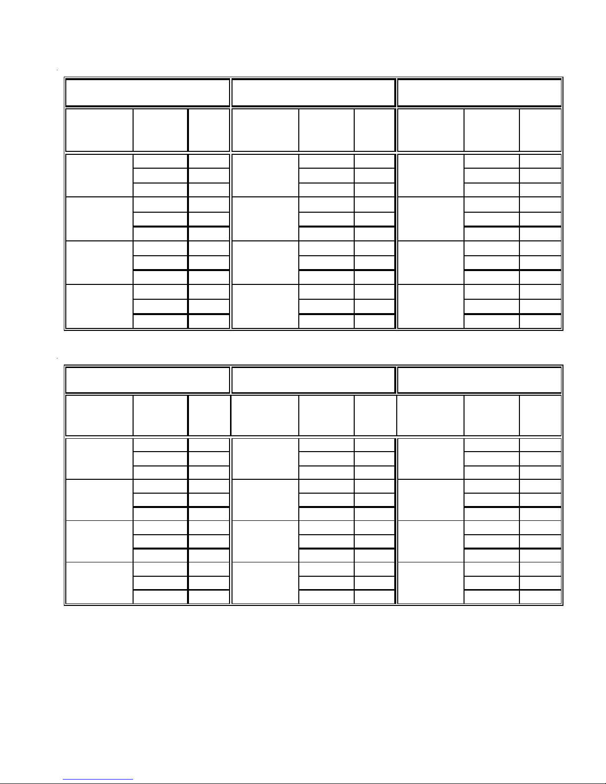
BLOWER PERFORMANCE SPECIFICATIONS
(+)
(+)
)
ADVC8 High (Single) Stage Cooling Speed Charts
ADVC 80703C X** AD V C 809 05C X* * ADVC81 155C X**
Coolin g
Speed Tap
Adjust
Tap
CFM
Cooling
1
Spe ed Tap
Adjust
Tap
Mi nus (-) 540 Mi nus (-) 720 Minus (-) 765
AAA
Normal 600 Normal 800 Normal 850
Plus (+) 660 P lus (+) 880 Plus (+) 935
Mi nus (-) 720 Mi nus (-) 990 Minus (-) 1035
BBB
Normal 800 Normal 1100 Normal 1150
Plus (+) 880 Plus (+) 1210 P lus (+) 1265
Mi nus (-) 900 Mi nus (-) 1260 Minus (-) 1305
CC
Normal 1000 Normal 1400 Normal 1450
Plus (+) 1100 Plus (+) 1540 Plus (+) 1595
Mi nus (-) 1080 Minus (-) 1620 Minus (-) 1665
DD
Normal 1200 Normal 1800 Normal 1850
Plus
1320 Plus (+)1980 P lus (+)2,000*
ADVC8 Low Stage Cooling Speed Charts
ADVC80703CX** ADVC80905CX**
Cooling
Speed Tap
Adjust
Tap
CFM
Cooling
1
Speed Tap
Adjust
Tap
CFM
CFM
Cooling
1
Speed Tap
Cooling
1
Speed Tap
Adjust
Tap
C
D
ADVC81155CX**
Adjust
Tap
CFM
CFM
1
1
Minus ( -) 351 Minus (-) 468 Minus (-) 497
Normal 390 Normal 520 Normal 553
Plus (+) 429 Plus (+) 572 Plus (+) 608
Minus ( -) 468 Minus (-) 644 Minus (-) 673
BB
Normal 520 Normal 715 Normal 748
Plus (+) 572 Plus (+) 787 Plus (+) 822
Minus ( -) 585 Minus (-) 819 Minus (-) 848
CC
Normal 650 Normal 910 Normal 943
Plus (+) 715 Plus (+) 1001 Plus (+) 1037
Minus ( -) 702 Minus (-) 1053 Minus (-) 1082
DD
1. Units are shipped without filter(s). CFM in chart is without filter(s).
2. All furnaces shipped with heating speed set at "B" and cooling speed set at "D". Installer should adjust blower speed
as needed. The first task is to determine the proper aiflow for the cooling system.
3. For most cooling applications, about 400 CFM per ton is desirable.
4. The chart is for information only. For satisfactory operation, external static pressure not to exceed value shown on
rating plate.
5. Do not operate above 0.5" w.c. ESP in heating mode. Operating between 0.5" w.c. and 0.8" w.c. is tabulated for cooling
purposes only.
6. * Motor CFM maximum.
Normal 780 Normal 1170 Normal 1203
Plus
858 Plus (+)1287 Pl us (+
AAA
B
C
D
1323
21
Page 22
BLOWER PERFORMANCE SPECIFICATIONS
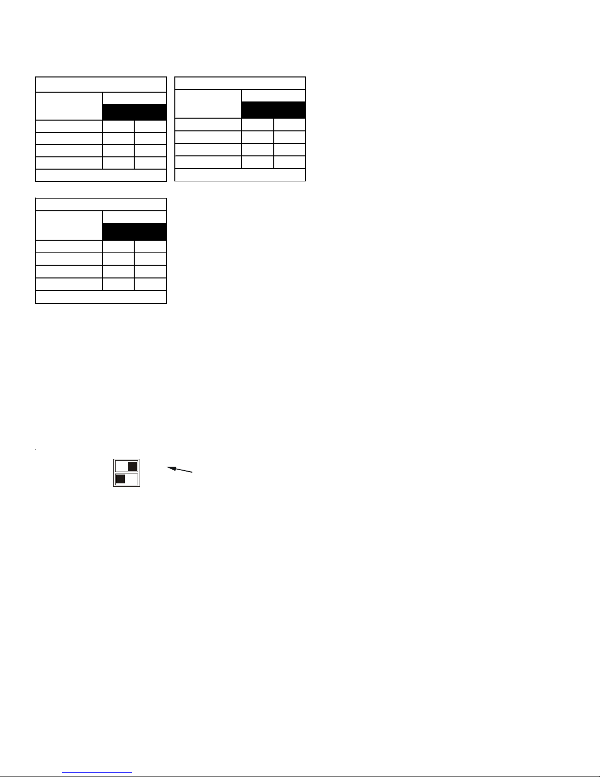
NOFF
Circulator Blower Speed Adjustment Switches
Switch Bank: S3
Cooling Speed
Taps
AOFFOFF
BONOFF
COFFON
D* ON ON
(*Indicates factory setting)
DIP S w itch No .
12
Switch Bank: S3
A djust Taps
Normal* OFF OFF
10% ON OFF
-10% OFF ON
Normal ON ON
(*Indicates f actory setting)
DIP Sw itch No.
34
Note: There are dual 7-segment LED's adjacent
to the selection dipswitches. The airflow rounded
to the nearest 100 CFM, is displayed on the dual
7-segment LED's. The CFM display alternates
with the operating mode.
Example:
If the airlfow demand is 1230 CFM, the LED's will
display 12. If the airflow demand is 1275 CFM,
the LED's will display 13.
Switch Bank: S4
Heating Speed
Taps
AOFFOFF
B* ON OFF
COFFON
DONON
(*Indicates factory setting)
DIP Sw itch No.
78
Dehumidification Enable Switch
O
9
10
S5
DEHUM
Unused
Move to the ON position
to enable dehumidification
Note: Continuous fan speed will be 30% of the
furnace's maximum airflow capability. If the furnace maximum CFM capaibility is 1760 CFM, the
continuous fan speed will be 0.30 X 1760 CFM =
530 CFM.
Example: If the furnace maximum CFM capaibility
is 1760 CFM, the continuous fan speed will be
0.30 X 1760 CFM = 530 CFM.
Note: The optional usage of a dehumidistat allows
the furnace’s circulator blower to operate at a slightly
lower speed (85% of desired speed) during a combined
thermostat call for cooling and dehumidistat call for
dehumidification. This can be done through an
independent dehumidistat or through a thermostat’s
DEHUM terminal (if available). This lower blower speed
enhances dehumidification of the conditioned air as it
passes through the AC coil. For proper function, a
dehumidistat applied to this furnace must operate on
24 VAC and utilize a switch which opens on humidity
rise.
1. Units are shipped without filter(s). CFM in chart is without filter(s).
2. All furnaces shipped with heating speed set at "B" and cooling speed set at "D". Installer should adjust blower speed
as needed. The first task is to determine the proper aiflow for the cooling system.
3. For most cooling applications, about 400 CFM per ton is desirable.
4. The chart is for information only. For satisfactory operation, external static pressure not to exceed value shown on
rating plate.
5. Do not operate above 0.5" w.c. ESP in heating mode. Operating between 0.5" w.c. and 0.8" w.c. is tabulated for cooling
purposes only.
6. * Motor CFM maximum.
22
Page 23
BLOWER PERFORMANCE SPECIFICATIONS
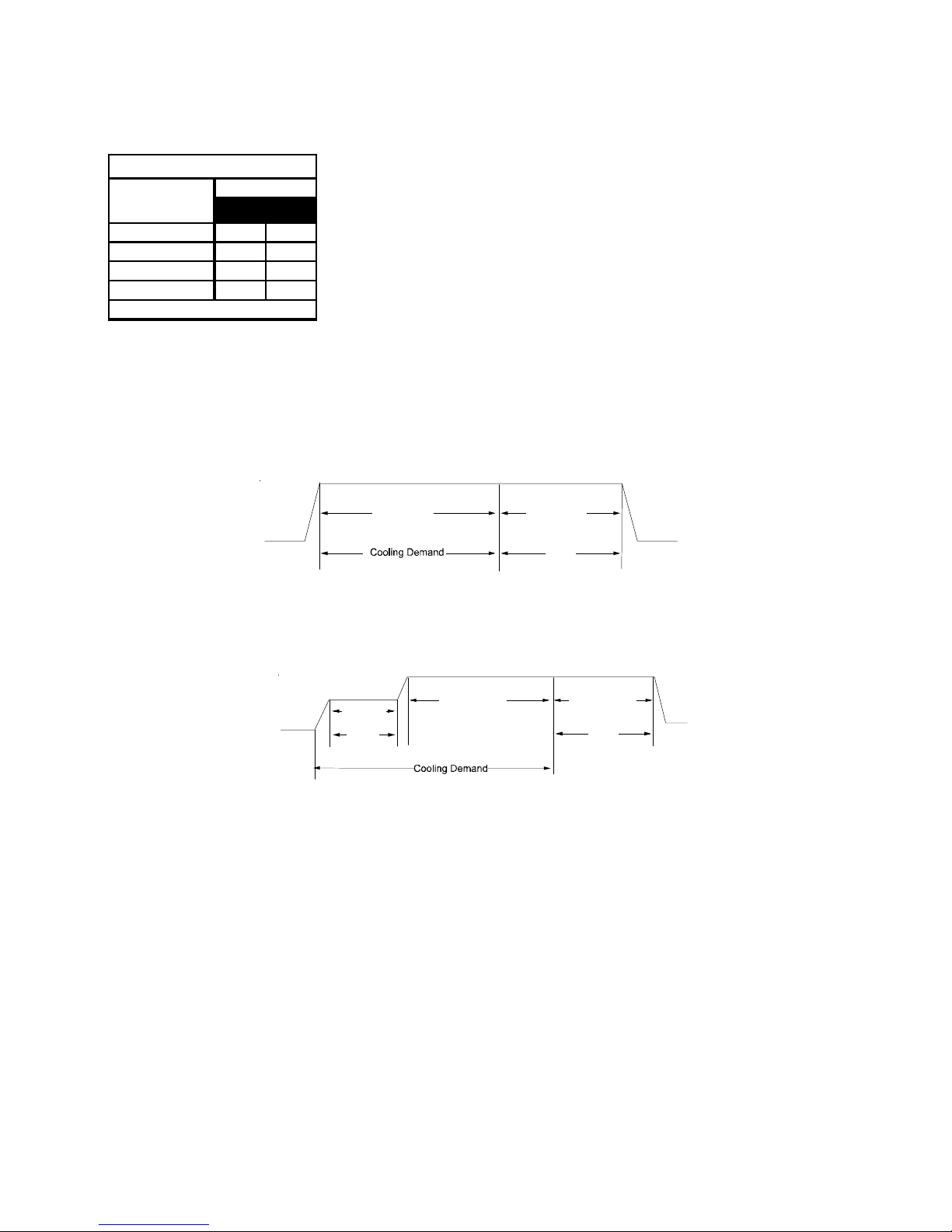
Ramping Profile
Switc h Bank: S4
Ramping
Profiles
A* OFF OFF
BONOFF
COFFON
DONON
(*Ind i cates facto ry setting )
DIP Switch No.
56
OFF
Profile A: provides only an OFF delay of one (1) minute at
100% of the cooling demand airflow.
Note: The multi-speed circulator blower also offers several
custom ON/OFF ramping profiles. These profiles may be
used to enhance cooling performance and increase comfort
level. The ramping profiles are selected using DIP switches
5 and 6. Refer to the following figure for switch positions
and their corresponding taps. Refer to the bullet points below
for a description of each ramping profile. Verify CFM by
noting the number displayed on the dual 7-segment LED
display.
100% CFM 100% CFM
OFF
1 min
OFF
Profile B: ramps up to full cooling demand airflow by first
stepping up to 50% of the full demand for 30 seconds. The
motor then ramps to 100% of the required airflow. A one (1)
minute OFF delay at 100% of the cooling airflow is provided.
1. Units are shipped without filter(s). CFM in chart is without filter(s).
2. All furnaces shipped with heating speed set at "B" and cooling speed set at "D". Installer should adjust blower speed
as needed. The first task is to determine the proper aiflow for the cooling system.
3. For most cooling applications, about 400 CFM per ton is desirable.
4. The chart is for information only. For satisfactory operation, external static pressure not to exceed value shown on
rating plate.
5. Do not operate above 0.5" w.c. ESP in heating mode. Operating between 0.5" w.c. and 0.8" w.c. is tabulated for cooling
purposes only.
6. * Motor CFM maximum.
50% CFM
1/2 min
100% CFM
100% CFM
OFF
1 min
23
Page 24
BLOWER PERFORMANCE SPECIFICATIONS
Ramping Profile
OFF
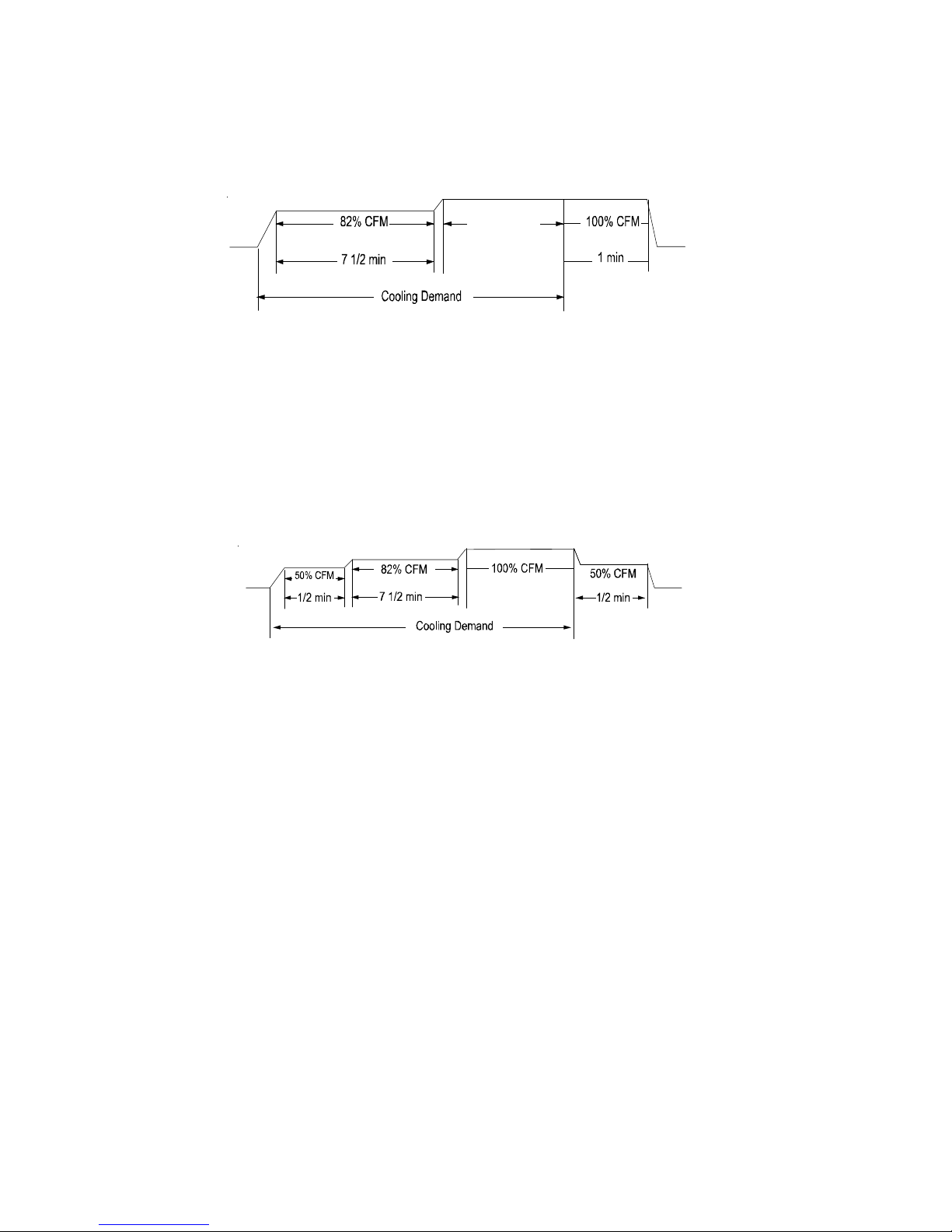
Profile C: ramps up to 82% of the full cooling demand airflow
and operates there for approximately 7 1/2 minutes. The motor
then steps up to the full demand airflow. Profile C also has a
one (1) minute 100% OFF delay.
OFF
100% CFM
OFF
OFF
Profile D: ramps up to 50% of the demand for 1/2 minute,
then ramps to 82% of the full cooling demand airflow and
operates there for approximately 7 1/2 minutes. The motor
then steps up to the full demand airflow. Profile D has a 1/2
minute at 50% airflow OFF delay.
1. Units are shipped without filter(s). CFM in chart is without filter(s).
2. All furnaces shipped with heating speed set at "B" and cooling speed set at "D". Installer should adjust blower speed
as needed. The first task is to determine the proper aiflow for the cooling system.
3. For most cooling applications, about 400 CFM per ton is desirable.
4. The chart is for information only. For satisfactory operation, external static pressure not to exceed value shown on
rating plate.
5. Do not operate above 0.5" w.c. ESP in heating mode. Operating between 0.5" w.c. and 0.8" w.c. is tabulated for cooling
purposes only.
6. * Motor CFM maximum.
24
Page 25
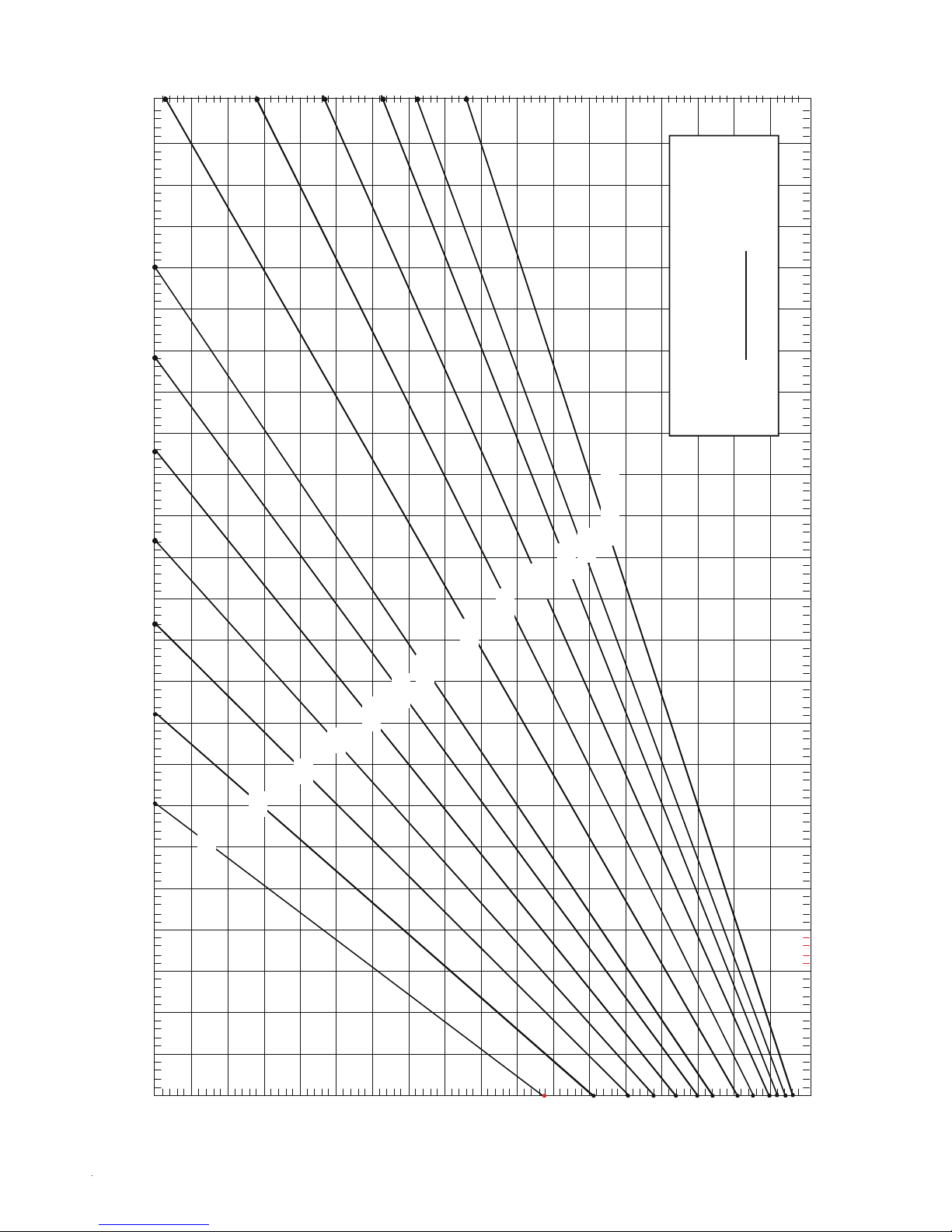
PERFORMANCE
MPER
RE R
÷ CFM
130 140 150
900
FORMULAS
BTU OUTPUT = CFM x 1.08 x RISE
1.08
BTU OUTPUT
RISE =
100
2400 CFM
2200
2000
1800
1600
1400
1200
1100
1000
OUTPUT BTU/HR x 1000
800
90
700
80
BTU OUTPUT vs TEMPER ATURE RISE CHART
600 CFM
100
70
30 40 50 60 70 80 90 110 120
60
ISE
50
ATU
TE
40
30
20
10
25
Page 26
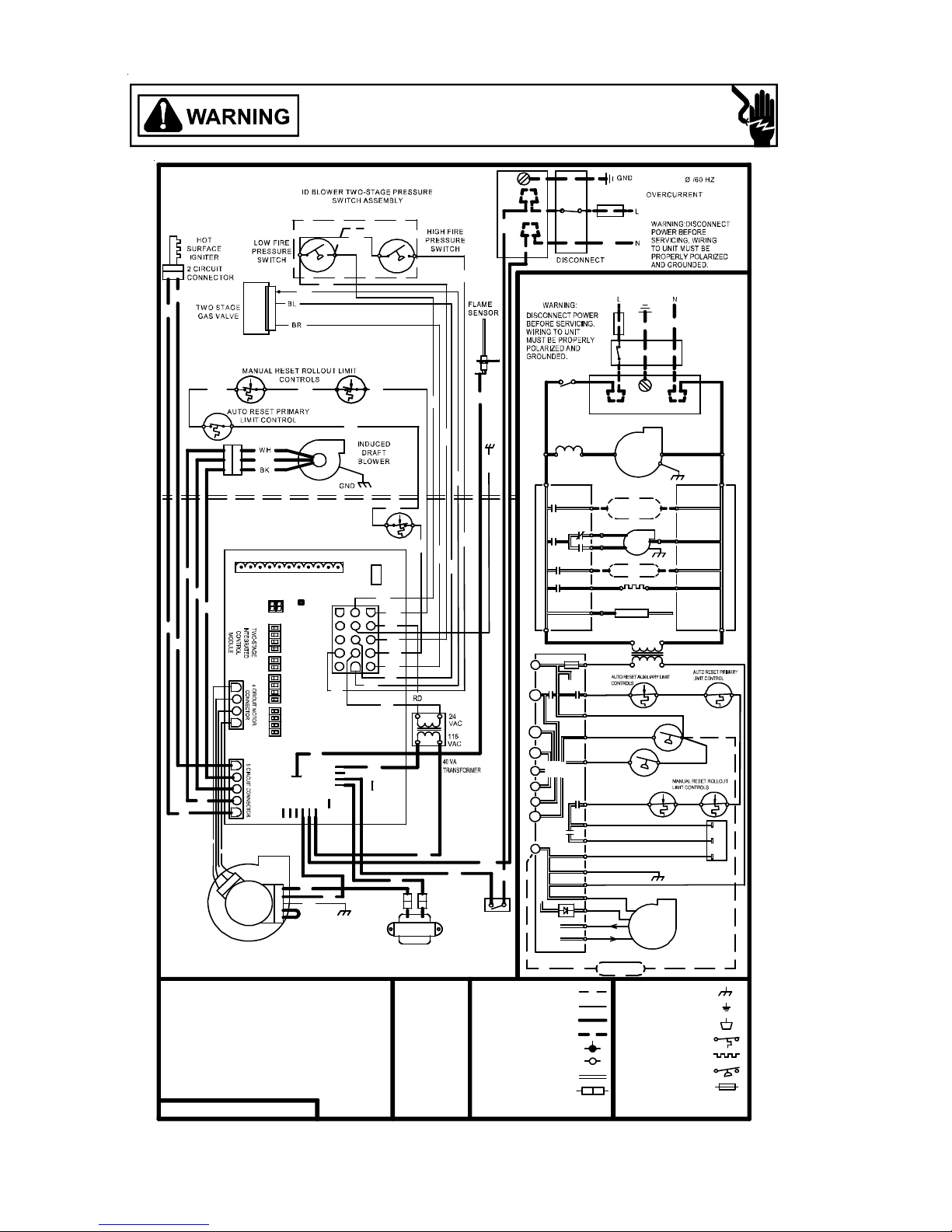
WIRING DIAGRAMS
A
A
A
A
HIGH VOLTAGE!
DISCONNECT ALL POWER BEFORE SERVICING OR INSTALLING THIS
UNIT. MUL TIPLE POWER SOURCES MAY BE PRESENT. FAILURE TO
DO SO MAY CAUSE PROPERTY DAMAGE, PERSONAL INJURY OR DEATH.
2
1
BK
WH
3
I
H
WH
2
C
1
PM
*MVC8***AA Models
TO
/
5
C
1
1
V
A
1
P
P
S
P
O
R
W
GND
P
R
CTI
E
E
O
T
ON DEV
C
JUNCTION BOX
B
24V HUM.
YL
C
O
N
C
NO
YL
K
WH
YL
TO 115VAC/ 1
Ø /60 HZ POWER SUPPLY WITH
OVERCURRENT PROTE
H
LY WI
T
U
D
T
O
N
EVI
C
E
I
ICE
PU
PU
PU
3
2
R
D
1
A
B
U
NER COM
R
O
B
WER COM
L
WH
24 V
O
DEHUM
P
R
P
A
H
T
ERMOSTAT CO
Y2
Y1
T
TM
E
N
T
TME
N
R
AUTO RESET
AUXILIARY
LIMIT CONTROL
E
N
N
CTION
S
2
1
G
W1
R
C
W2
RD
BK
DIAGNOSTIC
WH
LED'S
BK
1
2
3
4
1
2
3
4
WH
M
E
0
RD
R
T
S
S
G
B
CIRCULATOR
BLOWER
F
0
0
5
L
B
Y
4
K
3
2
1
6
0
6
WH
M
C
E
N
HAR
NOTES:
1. SE T HEAT ANTI CIPATOR ON RO
2. MANUFACTURER'S SPECIFIED REPLACEMENT PARTS MUST BE
USED WHEN SERVICING.
3. IF ANY OF THE ORIGINAL WIRE A S S UP P L IE D WITH THE
FURNACE MUST BE REPLACED, IT MUST BE REPLACED WITH
WIRING MATERIAL HA VING A TEMPERATURE RATING OF AT
LEAST 105°C. USE COPPER CONDUCTORS ONL Y.
4. UNIT MUST BE PERMANENTLY GROUNDED AND CONFOR
N.E.C. AND LOCAL CODES.
5. TO RECALL THE LAST 6 FAUL TS, MO ST RECENT TO LEAST
RECENT, DEPRESS SWITCH FOR MORE THAN 2 SECONDS WHILE
IN STANDBY (NO THERMOSTAT INPUTS)
1
4
0
DIP SWITCHES
5
4
3
2
1
OM THERMO
R
E
2ND STG DLY
T-ST AT
HEAT OFF
DELAY
UNUSED
DEHUM
HEAT
DELAY
DJUST
COOL
S
F
NEUTRAL
BK
GR
PK
STAT AT 0.7 AMPS.
.
A
V
SEE
NOTE 5
OR
3
6
9
12
15
YL
LINE
HUM
WH
M T
O
2
5
8
11
14
GND
RD
FUSE
YL
1
4
7
10
13
WH
BK
EAC
PU
4
2
V
A
3
RD
RD
YL
RD
BR
B
L
BL
WH
B
K
INDUCTOR COIL
70kBTU,90kBTU,
115kBTU MODE LS
ONLY
COLOR CODES:
PK PINK
BR BROWN
WH WHITE
BL BLUE
GY GRAY
RD RED
Y
O
PU PURPLE
GN GREEN
BK BLACK
CHASSIS GROU ND
DISCONNECT
YL
OR
YL
GN
WH
YL
RD
BR
BL
WH
BK
BLOWER
COMPARTMENT
DOOR SWIT CH
(OPEN WHEN
DOOR OPEN)
B
K
LOW VOLTAGE (24V)
LOW VOLTAGE FIELD
HI VOLTAGE (115
L
HI VO
L
L
E
O
Y
L
W
G
R
OR
A
E
N
INTERN
INTEGRAT
PLUG CONNECTION
DOOR
SWITCH
INDUCTO
70kBTU,90kBTU,
115 kBTU MODELS
E
LIN
INTEGRATED CO NTRO L MODULE
LINE
FUSE 3 A
R
TO
24V THERMOSTAT CONNECTIONS
Y1
W1
W2
TO
MICRO
Y2
G
O
D
E
H
U
M
24V HUM.
C
O
T
R
T
O
O
MIC
R
INTEGRATED CONTROL MODULE
V)
E
F
G
A
T
IELD
JUNCTION
E
T
R
M
I
A
N
TO
AL
NTROL
ED CO
+
L
ONLY
V
EAC
HUM
IGN
D
R COI
IND HI
IND LO
FS
TH (4)
C
HLO (10)
PSO (7)
PS1 (2)
2
P
S
HIGH FI RE
PRESS. SWTICH
HLI (1)
MVL (1 3)
MVH (14)
MVC (8)
GND (5)
TR (11)
D
N
G
+ VDC
(
X
R
X
(
T
JUNCTION BOX
L
INDOOR
CIRCULATOR
BLWR
ELECTRONIC
IR CLEANE R
ID
BLWR
HUMIDIFIER
HOT SURFACE
IGNITER
FLAME SENSOR
24V HUM.
NO
)
2
1
(
4
)
(
1
(
)
2
)
C
)
3
F
HUMID
I
I
E
EQUIPMENT GND
SWITCH (TEMP.)
SWITCH (PRESS
IR
115 VAC
40 VA
TRANSFORMER
24 VAC
NO
C
GND
I
N
R
O
O
D
AIR
L
U
C
R
I
T
O
R
BLWR
R
FIELD G
FIELD SPLICE
I
N
G
I
C
R
E
V
URR
O
PROT. D EVICE
GND
NEUTRAL
NEUTRAL
NEUTRAL
NEUTRAL
NEUTRAL
NEUTRAL
LOW FIRE PRESS.
SWITCH
C
ND
R
T
E
.)
T
N
E
GAS
VALVE
INTEGRATED CONTROL M ODUL E
PM
HI
C
Wiring is subject to change. Always refer to the wiring diagram on the unit for the most up-to-date wiring.
26
Page 27
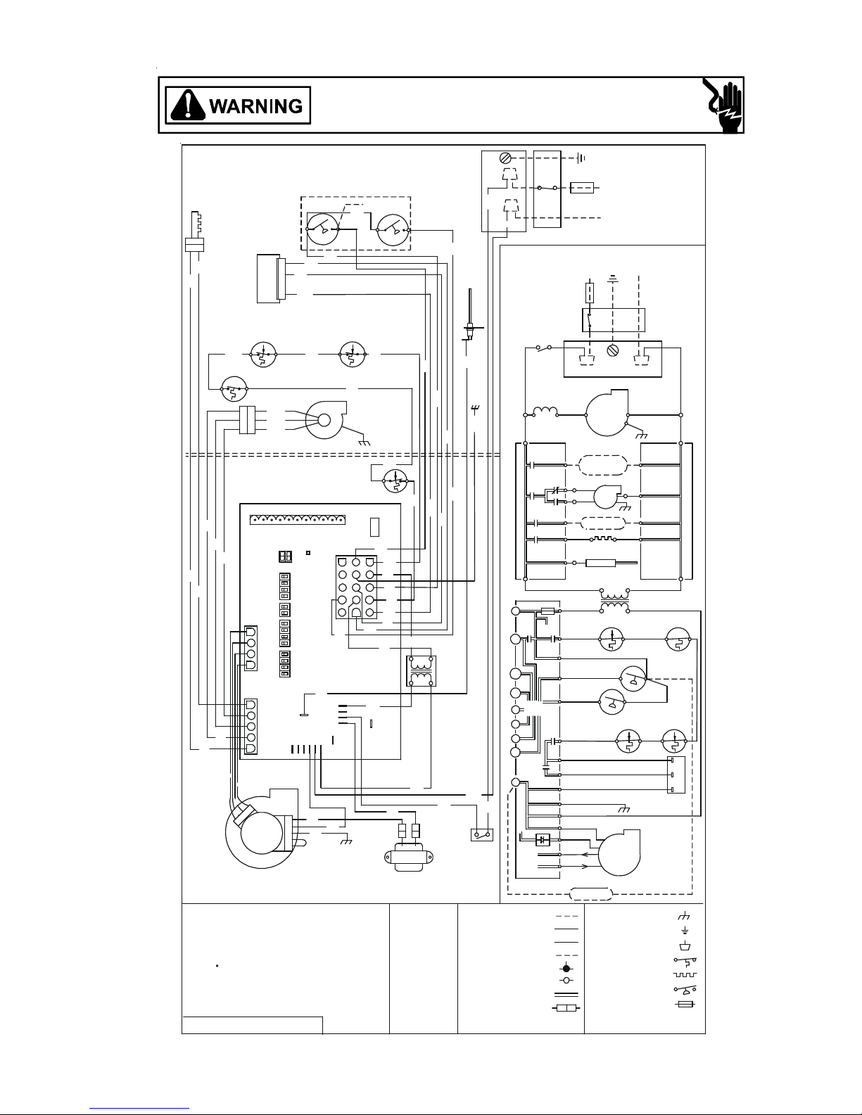
WIRING DIAGRAMS
A
A
A
HIGH VOLTAGE!
DISCONNECT ALL POWER BEFORE SERVICING OR INSTALLING THIS
UNIT. MUL TIPLE POWER SOURCES MAY BE PRESENT. FAILURE TO
*MVC8***AB, *DVC8***AA Models
DO SO MAY CAUSE PROPERTY DAMAGE, PERSONAL INJURY OR DEATH.
TO
GND
115 VAC / 1
Ø /60 HZ
POWER SUPPLY W ITH
OVERCURRENT
PROTECTION DEVICE
WARNING:DISCONNECT
POWER BEFORE
SERVICING. WIRING
TO UNIT MUST BE
PROPERLY POLARIZED
AND GROUNDED.
GND
N
DISCONNECT
GND
NEUTRAL
NEUTRAL
NEUTRAL
NEUTRAL
NEUTRAL
NEUTRAL
40 VA
TRANSFORMER
AUTO RESET PRIMARY
LIMIT CONTROL
LOW FIRE PRESS.
SWITCH
C
NO
C
MANUAL RESET ROLLOUT
LIMIT CONTROLS
GAS
VALV E
GND
INDOOR
AIR
BLWR
FIELD GND
IGNITER
I
N
T
E
G
R
A
T
E
D
C
O
N
T
R
O
L
M
O
D
U
L
E
PM
HI
C
YL
FLAME
SENSOR
OR
YL
WH
YL
BL
24
VAC
115
VAC
40 VA
TRANSFORMER
WH
BK
BLOWER
COMPARTMENT
DOOR SWITCH
(OPEN WHEN
DOOR OPEN)
LOW VOLTAGE ( 24V)
LOW VOLTAGE FIELD
HI VOLTAGE (115V)
HI VOLTAGE FIELD
INTEGRATED CONTROL
JUNCTION BOX
BK
WH
TO 115VAC/ 1
WARNING:
DISCONNECT POWER
BEFORE SER VICING.
WIRING TO UNI T
MUST BE PROPERLY
POLARIZED AND
GROUNDED .
CHASSIS GROUND
GN
I
N
T
E
G
R
A
T
E
D
C
O
N
T
R
O
L
M
O
D
U
L
E
R
Y1
2
4
V
T
H
E
R
W1
M
O
S
T
W2
T
C
O
N
Y2
N
E
C
T
G
I
O
N
S
O
DEHUM
2
4
V
H
U
M
C
.
BK
TO
R
MICRO
INTEGRATED CONTROL MODULE
JUNCTION
TERMINAL
INTERNAL TO
PLUG CONNE CTION
L
N
DISCONNECT
Ø /60 HZ POWER SUPPLY WITH
OVERCURRENT PROTECTION DE VICE
DOOR
SWITCH
INDUCTOR CO IL
70kBTU,90kBTU,
115kB TU MOD ELS
LINE
LINE
FUSE 3 A
TO +VDC
TO
MICRO
TO
ONLY
EAC
ELECTRONIC
AIR CLEANER
IND HI
IND LO
HUM
HUMIDIFIER
IGN
HOT SURFACE
FS
FLAME SENSOR
TH (4)
AUTO RESET AUXILIARY L IMIT
CONTROLS
HLO (10)
PSO (7)
PS1 (2)
PS2 (12)
HIGH FIRE
PRESS. SWTICH
HLI (1)
MVL (13)
MVH (14)
MVC (8)
GND (5)
TR (11)
GND (4)
+ VDC (1)
RX (2)
TX (3)
HUMIDIFIER
L
JUNCTION BOX
INDOOR
AIR
CIRCULATOR
BLWR
ID
BLWR
IGNITER
115 VAC
24 VAC
24V HUM.
NO
CIRCULATOR
EQUIPMENT GND
FIELD SPLICE
SWITCH (TEMP.)
SWITC H (PRESS.)
OVERCURRENT
PROT. DEVICE
ID BLOWER TWO-STAGE PRESSURE
SWITCH ASSEMBL Y
24V HUM.
C
NO
YL
AUTO RESET
AUXILIARY
LIMIT CONTROL
R
C
YL
RD
PU
INDUCED
DRAFT
BLOWER
GND
FUSE
1
2
2
1
BK
WH
HOT
SURFACE
IGNITER
2 CIRCUIT
CONNECTOR
TWO STAGE
GAS VALVE
(HONEY WELL)
WH
LOW FIRE
PRESSURE
SWITCH
2
HI
3
BL
C
1
PM
MANUAL RESET ROLLOUT LIMIT
LIMIT CONTROL
3
WH
2
RD
1
BK
CONTROLS
PU
AUTO RESET PRIMARY
BURNER COMPARTMENT
BLOWER COMPARTMENT
24 V THERMOSTAT CONNECTIONS
W2
DEHUM
W1
Y2
Y1
O
WH
BR
PU
G
RD
BK
DIAGNOSTIC
WH
RD
LED'S
INTEGRATED
T
W
CONTROL
MODULE
O
-
S
T
G
E
4 CIRCUIT MOTOR
1
CONNECTOR
2
3
4
5 CIRC UIT CONNEC TOR
1
2
3
4
5
BL
GY
4
BK
3
2
1
CIRCULATOR
BLOWER
WH
BK
WH
ECM MTR
HARNESS
NOTES:
1. SET HEAT ANTICIPATOR ON ROOM THERMOSTAT AT 0.7 AMPS.
2. MANUFACTURER'S SPECIFIED REPLACEMENT PARTS MUST BE
USED WHEN SERVICING.
3. IF ANY OF THE ORIGINAL WIRE AS SUPPLIED WITH THE
FURNACE MUST BE REPLACED, IT MUST BE REPLACED WITH
WIRING MATERIAL HAVING A TEMPERATURE RATING OF AT
LEAST 105 C. USE COPPER CONDUCTORS ONLY.
4. UNIT MUST BE PERMANENTLY GROUNDED AND CONFORM TO
N.E.C. AND LOCAL C ODES.
5. TO RECALL THE LAST 6 FAULTS, MOST RECENT TO LEAST
RECENT, DEPRESS SWITCH FOR MORE THAN 2 SECONDS WHILE
IN STANDBY (NO THERMOSTAT INPUTS)
DIP SWITCH ES
2ND STG DLY
T-STAT
HEAT OFF
DELAY
UNUSED
DEHUM
HEAT
DELAY
ADJUST
COOL
FS
NEUTRAL
5
4
3
2
1
BK
GR
PK
SEE
NOTE 5
OR
HUM
WH
YL
2
1
3
6
4
5
9
7
8
10
12
11
15
13
14
WH
YL
LINE
BK
E
C
GND
C
NO
PU
24 V
3 A
RD
RD
YL
RD
BR
BL
BL
BK
INDUCTOR COIL
70kBTU,90kBTU,
115kBTU MODELS
ONLY
COLO R CODES:
PK PINK
BR BROWN
BL BLUE
GY GRAY
RD RED
PU PURPLE
GN GREEN
BK BLACK
HIGH FIRE
PRESSURE
SWITCH
YL
RD
BR
RD
WH
WH WHITE
YL YELLOW
OR ORANGE
0140F00660 REV. A
Wiring is subject to change. Always refer to the wiring diagram on the unit for the most up-to-date wiring.
27
Page 28
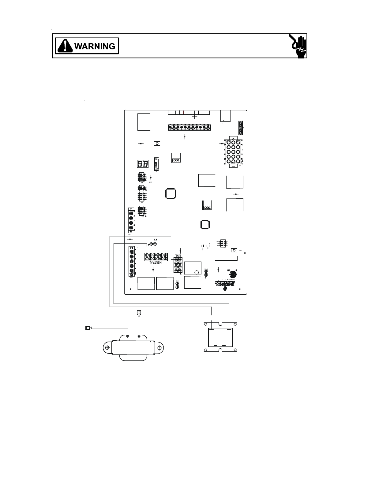
SCHEMATICS
HIGH VOLTAGE!
DISCONNECT ALL POWER BEFORE SERVICING OR INSTALLING THIS
UNIT. MUL TIPLE POWER SOURCES MAY BE PRESENT. FAILURE TO
DO SO MAY CAUSE PROPERTY DAMAGE, PERSONAL INJURY OR DEATH.
INTEGRATED CONTROL MODULE
HUM
Y2
DE
Y1
Y2
DEHUM
Y1Y1O
Y21DEHUM
R
W2
W1
C
GO
2
G
W2
R
W1
C
2 O
W2
W1
G1
2
R
C
1
1
3
6
9
12
15
4
7
10
13
ST5
INDUCTOR COIL
GND
TX
RX
12V
ST4
FS
WH
IGN-N
IND-N
IND-LO
IND-HI
IGN
BK
R
ANSI Z21 .20 AU TOMATIC IGNITIO N SYST EM 24VAC 60Hz 0 .8 A. M AX.
EAC
HUM
BK
WH
59-4715 R EV. F
LINE
LOAD
TRANSFORMER
ADVC8/AMVC8/GMVC8_____X* MODEL FURNACES
This schematic is for reference only. Not all wiring is as shown above,
refer to the appropriate wiring diagram for the unit being serviced.
Wiring is subject to change. Always refer to the wiring diagram on the unit for the most up-to-date wiring.
28
CONTROL ASSEMBLY SCHEMATIC
Page 29
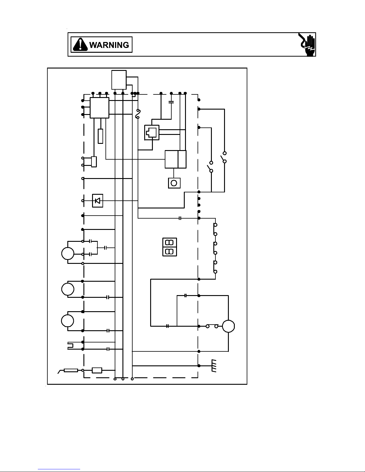
SCHEMATICS
Y2
O
W2
W1
HIGH VOLTAGE!
DISCONNECT ALL POWER BEFORE SERVICING OR INSTALLING THIS
UNIT. MUL TIPLE POWER SOURCES MAY BE PRESENT. FAILURE TO
DO SO MAY CAUSE PROPERTY DAMAGE, PERSONAL INJURY OR DEATH.
XFMR
G
DEHUM
P
μ
C
4
8
R
Y112
6
N/C
122
DIPSWX
334
TX/RX
1
VARIABLE SPEED
CIRCULATOR
HI
2
LO
3
INDUCER
4
EAC
RJ11
P
μ
RS485
COMM
COMM
STATUS LED
DU AL LED
DIS PLAY S
71593
101
PS2
PS1
N/C
AUXRLSHL
TYPICAL SCHEMATIC
14
WR 50C51-289 INTEGRATED IGNITION CONTROL
ADVC8/AMVC8/GMVC8_____X* MODEL FURNACES
HUM
15
IGN
Z CNTL
Wiring is subject to change. Always refer to the wiring diagram on the unit for the most up-to-date wiring.
DRAIN
SWITC H
LO HI
138
GAS VALVE
5-11
GROU ND
WIRING SCHEMATIC
This schematic is for reference only. Not all wiring is as shown above. Refer to the appropriate wiring diagram for the unit being serviced.
29
 Loading...