

Page 1
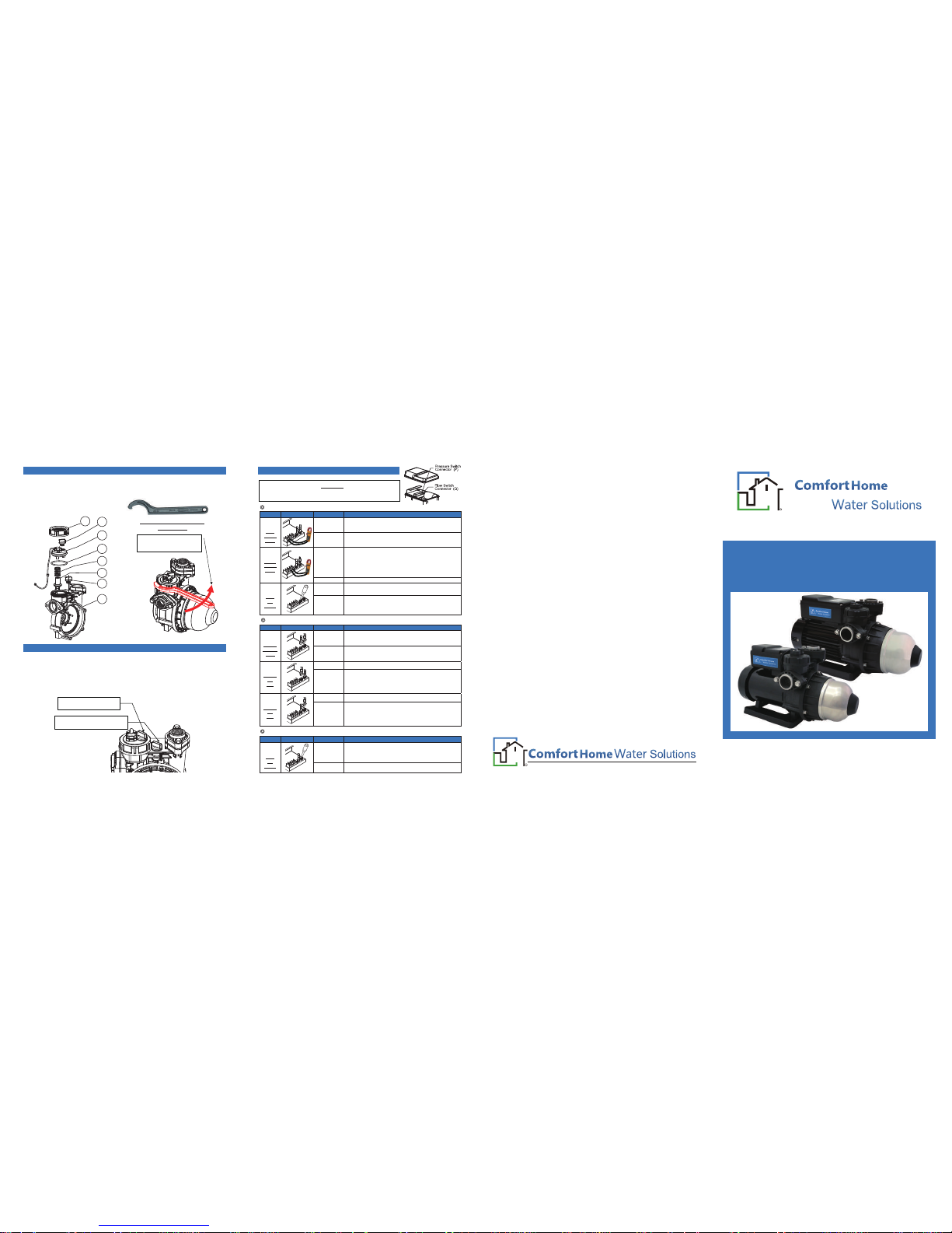
ASB Series
Installation and Operating Instructions
Auto Silent Booster Pump
Din 1810 Form A No.40 68-75
hook wrench
Unscrew the “Locking Ring
(Part No.22-4)” to disassemble
the flow switch.
Discharge Side
Air Evacuation Plug (Part No. 21-2)
Suction Side
Priming Plug (Part No. 21-1)
Flow Switch Disassembly
Pump Trapped-Air Evacuation
21-1
22-4
22-0
22-3
22-2
22-1
21-2
3
The flow switch can be disassembled or replaced by using a “Din 1810 Form A
No.40 68-75 hook wrench” or other similar pipe wrench to unscrew the “Locking
Ring (Part No. 22-4)”
The filling of suction piping and pump chamber must be very carefully to ensure
no any air inside. Trapped-air will cause pump low discharge / pressure, and
resulting abnormal operation. Trapped-Air evacuation can be accomplished by
opening all discharge valves, or unscrewing the discharge side “Priming Plug
(Part No. 21-2)” during pump operation.
PROBLEM – Pumps fail to start when the discharge devices are opened.
Test Schematic Status
Voltage
is normal
Go to test “A-2".
A-1
Input
Voltage
Check
No power
Check the controller power source and circuit breaker.
Voltage
is normal
1: Turn the power off, and check if the motor rotate manually.
2: If the motor or pump casing is overheating, the motor
winding or pump casing thermostat might be tripped due to
motor overloading or pump dry running. The motor will
start running automatically, when the motor winding or
pump casing temperature back to normal.
A-2
Output
Voltage
Check
No power Go to test “A-3”.
Motor still
fails to start
Replace the controller.
A-3
Short
“P”
Socket
Motor starts
running
1: Make sure the discharge device is fully opened, or
discharge piping is blocked.
2: Lower the pressure switch setting.
3: Replace the pressure switch.
PROBLEM – Pumps fail to stop after all the discharge appliances are closed.
Test Schematic Status
Motor stops
Go to test “B-2” and “B-3”.
B-1
Remove
“P” & “Q”
Plugs
Motor still
running
Replace the controller.
Motor Stops
The flow switch function is normal.
B-2
Remove
“P”
Plug
Motor still
running
1: Make sure if the flow switch is activated due to the leakage
of discharge piping or devices.
2: Clean the inlet check valve to ensure the flow switch can
back to normal position.
3: Replace the flow switch.
Motor Stops
The pressure switch function is normal.
B-3
Remove
“Q”
Plug
Motor still
running
1: Make sure the inlet water source is enough.
2: Check the suction piping for air-locked or leakage which
result low pump output pressure.
3: Lower the pressure switch setting.
4: Replace the pressure switch.
PROBLEM – Pumps cycle frequency or unstable under “Power ON”
Test Schematic Status
Motor back
to normal
1: Avoid small discharge piping leakage or operation which
will cause unstable flow switch ON/OFF switching.
2: Recharge pressure tank air up to 1~1.2 kg/cm
2
.
3: Replace the flow switch.
C-1
Short
“Q”
Socket
Motor still
unstable
Replace the controller.
CAUTION
PLEASE DO NOT ADJUST PRESSURE SWITCH SETTING UNLESS
Troubleshooting
Causes / Solutions
Causes / Solutions
Causes / Solutions
ALL THE TROUBLESHOOTING PROCESS HAS BEEN DONE.
R
Comfort Home
Limited Warranty:
Products of Comfort Home are warranted to the first user only to be free
of defects in material and workmanship for a period of 12 months from date
of installation, but no more than 24 months from date of manufacture.
Comfort Home's liability under this warranty shall be limited to repairing or
replacing at our election, without charge, FOB Comfort Home's distribution
center or authorized service agent. Comfort Home will not be liable for
any cost of removal, installation, transportation or any other charges that
may arise
in connection with warranty claim.
The warranty period commences on the date of original purchase of the
equipment. Proof of purchase and installation date, failure date, and
supporting installation data must be provided when claiming repairs
under
warranty.
This warranty is subject to due compliance by the original purchaser with
all directions and conditions set out in the installation and operating
instructions. Failure to comply with these instructions, damage or breakdown
caused by fair wear and tear, negligence, misuse, incorrect installation,
inappropriate chemicals or additives in the water, inadequate protection
against freezing, rain or other adverse weather conditions, corrosive or
abrasive water, lightning or high voltage spikes or through unauthorized
persons attempting repairs are not covered under warranty.
Comfort Home will not be liable for any incidental or consequential damages,
losses, or expenses, arising from installation, use, or any
other causes.
There are no express or implied warranties, including merchantability
or fitness for a particular purpose, which extend beyond those
warranties described or referred to above.
Certain countries do not permit the exclusion or limitation of incidental
or consequential damages or the placing of limitations on the duration
of an implied warranty, therefore, the limitations or exclusions herein
may not apply. This warranty sets forth specific legal rights and
obligations, however, additional rights may exist, which may vary from
countries to countries.
Supersedes all previous publications.
WEBSITE : www.comforthomewater.com
E-MAIL : [email protected]
R
Comfort Home
CCAASB0E01
Page 2
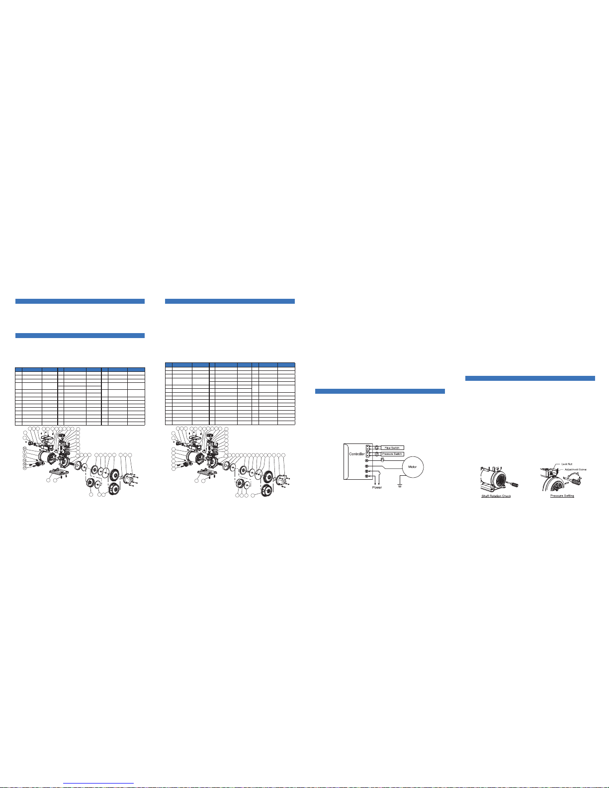
The ASB series booster pump is an all-in-one compact and reliable automatic
multistage centrifugal booster pump, which integrates motor, pump, accumulator,
pressure switch and flow switch in one set. The flow switch equipped with the
pump prevents the pump from continuously starting and stopping under small
discharge, and provide stable water supply. It is very suitable for domestic water
supply.
Operating Conditions
1. Ambient Temperature : +5 ºC ~ +40 ºC
2. Liquid Temperature
Regular Model : +5ºC ~ +40ºC
Hot Water Model : +5ºC ~ +90ºC
3. Maximum Operating Pressure
: 6 kg/cm
2
4. Rated Discharge Head / Height
ASB25(H) : 1.5 kg/cm2 / 15 m
ASB50(H) : 2.0 kg/cm2 / 20 m
ASB100(H) : 2.5 kg/cm
2
/ 25 m
Item Name Description Item Name Description Item Name Description
1 Motor 1Φ 2 Poles 15 Inlet Flange Gasket Rubber 25 Bolt S45C
2 Bolt S45C 16 Inlet Flange NYLON 26 Wiring Box Cover NYLON
3 Pump Casing Noryl 17 Flange Bolt SUS304 27 Bolt S45C
18 Outet Flange Gasket Rubber
4 Mechanical Seal
Ceramic+NBR
+Carbon
19 Outlet Flange NYLON
28 Controller
Triac-Based
5 Impeller Chamber NORYL 20 Flange Bolt SUS304
6 Impeller NORYL 21-1 Priming Plug NYLON
29 Pressure Switch
For Turn-On
Pressure Setting
7 Diffuser NORYL 21-2 Air Evacuation Plug NYLON 30 Switch Cover NYLON
8 Impeller NORYL 22-0 Flow Switch Set Flow Detection 31 Thermal Protector Auto Reset
9 O Ring NBR 22-1 Spring SUS304 32 Pump Base ABS
10 Bolt SUS304 22-2 Stopper NORYL 33 Bolt S45C
11*1 Pump Cover NYLON 22-3 Seal O Ring NBR 34*2Impeller Chamber NORYL
12 O Ring NBR 22-4 Locking Ring NYLON 35*2Impeller NORYL
13 Pressure Tank SUS304 23 Seal Gasket Rubber 36*2Pump Cover NYLON
14 Pump Cover Bolt SUS304 24 Wiring Box NYLON 37 Motor Capacitor Plastic Film
*1
Parts for 60 Hz models.
*2
Parts for 50 Hz models.
Installation and Piping
1.
For stable operation, please mount and bolt the booster pump securely. The
installation place must be dry with good ventilation and adequate space for
future maintenance and service. A proper shelter is required for outdoor
installation; exposure to rain will damage the insulation of electrical wiring.
Construction ( ASB-H Hot water Model with stainless steel impeller.)
Item Name Description Item Name Description Item Name Description
1 Motor 1Φ 2 Poles 13 Pressure Tank SUS304 24 Wiring Box NYLON
2 Bolt S45C 14 Pump Cover Bolt SUS304 25 Bolt S45C
3 Pump Casing Noryl 15 Inlet Flange Gasket Rubber 26 Wiring Box Cover NYLON
16 Inlet Flange NYLON 27 Bolt S45C
4 Mechanical Seal
Ceramic+ Viton
+Carbon*
3
17 Flange Bolt SUS304 28 Controller Triac Based
5 Impeller Chamber NORYL 18 Outlet Flange Gasket Rubber
6 Impeller SUS304*3 19 Outlet Flange NYLON
29 Pressure Switch
For Turn-On
Pressure Setting
6-1*3 Shaft Sleeve PPS 20 Flange Bolt SUS304 30 Switch Cover NYLON
7 Diffuser NORYL 21-1 Priming Plug NYLON 31 Thermal Protector Auto Reset
8 Impeller SUS304*3 21-2 Air Evacuation Plug NYLON 32 Pump Base ABS
8-1*3 Shaft Sleeve PPS 22-0 Flow Switch Set Flow Detection 33 Bolt S45C
9 O Ring NBR 22-1 Spring SUS304 34*2Impeller Chamber NORYL
10 Bolt SUS304 22-2 Stopper NORYL 35*2Impeller SUS304*3
10-1*3 Shaft Sleeve SUS304 22-3 Seal O Ring NBR 35-1*3Shaft Sleeve PPS
11*1 Pump Cover NYLON 22-4 Locking Ring NYLON 36*2Pump Cover NYLON
12 Tank O Ring Silicon Rubber*3 23 Seal Gasket Rubber 37 Motor Capacitor Plastic Film
Operation and Important Notes
Pressure Switch Adjustment
(a) Single Voltage Model Wiring
Description
Construction ( ASB Regular model with thermoplastic impeller.)
14
13
1211109
87
6
5
4
3
18
19
20
23
24
37
27
26
282529
30
27
30
27
31
15
16
17
32
33
32
33
34 35
36
34
35 36
141312111098
7
21-2
35-1
22-2
22-1
21-1
22-4
22-0
23
24
37
27
26
282529
21-1
6-1
8-1
22-4
22-0
22-3
18
19
20
21-2
22-2
22-1
10-1
22-3
1
2
654
3
2.
The pump should be installed as close as to the reservoir or well. For hot
water (40~90ºC) pumping, negative inlet pressure application is required to
avoid cavitations. Piping joints should be fitted carefully to prevent leak. Leak
in the suction piping will cause the pump suction capacity lost, while leak in
the discharge piping will cause a high frequency ON/OFF motor operation
while the faucets valves are closed.
*3 Parts or materials for hot water models
only.
*2 Parts for 50 Hz models.
*1 Parts for 60 Hz models.
3. Protection rubber films within the center of suction/discharge flange gaskets
(Part No. 15 & 18) muse be removed during installation.
4.
Be careful not to allow the foreign objects (PVC adhesive gum, dirt, sand etc)
into the pump, otherwise the pump will be damaged and shortened the life.
It is recommended to use a strainer to prevent that.
5.
Check the voltage and wiring of the motor power according to the connecting
diagram shown below or inside the cover. Be sure to arrange earth or circuit
breaker against electric leakage in accordance with local government electrical
code.
6.
The pump thermal protector (Part No. 31) is designed to protect the pump
from dry run. It is also used to prevent hot water pumping which will damage
the pump structure. The electrical power will be cut off after several minutes
while dry run occurs, and will be turned on periodically. Shut off the electrical
power manually is recommended during the water shortage period to save
the energy.
7. An auto-reset thermal protector is equipped with the motor winding. Power
will be cut off when the motor winding temperature is abnormal, and will
restart when the abnormal temperature back to normal.
1. Before set the power on, the pump chamber and suction pipe must be filled
with water in accordance with the following:
2. Insert a crossed screwdriver into motor shaft end, and turn the shaft several
turns clockwise to check whether the pump can be rotated freely. If not,
disassemble and clean the pump chamber.
3.
Double check the voltage and wiring of the motor power and then turn the
power switch ON. Open faucet or water appliances on the discharge piping
side. The water should be delivered after several seconds.
4. If the water does not be delivered after several minutes, turn off the pump
immediately. Repeat step 1 to pour water into the pump and suction piping,
and switch power ON and OFF continuously.
5. Once the water is pumped out, close and open the water appliances on the
discharge side repeatedly to check automatic ON/OFF operation.
6.
Measure the motor current and check with the data shown on the nameplate.
If the current is over, check the voltage again.
7. When re-start the pump after long term shut down, please repeat step1~6 to
ensure the normal operation.
The pressure switch set is designed inside the control box. In general, the
pressure has been set by factory properly to meet most situations. However,
for some special cases, when the pump cannot operate normally, it can be
adjusted easily. Please check the trouble shooting procedures, and read the
following instructions carefully before to do it. For pressure adjustment, first
remove the switch cover, and loose the lock nut counterclockwise by using a
12mm wrench.
1. Motor fails to stop
It is because of the pressure setting too high. By using a flat-end screwdriver,
turn the screw counterclockwise slowly, until the motor stop; then, turn an extra
small rotation, about 5 degrees. Finally, check if the motor can start normally.
2. Motor fail to start
It is because of the pressure setting too low. By using a flat-end screwdriver,
turn the screw clockwise slowly, until the motor start, then an extra small rotation,
about 5 degree, is added. Finally, check if the motor can stop normally.
3. After the pressure setting, screw the lock nut, and put the cover back.
◎
For the negative inlet pressure application ( inlet water level is below the pump
input ), remove the priming plugs (Part No. 21-1 or 21-2), and pour water into
the pump via priming hole completely. Then, secure the priming plugs back.
◎
For the positive inlet pressure application ( inlet water level is higher than
pump input ), loose the priming plug (Part No. 21-2), and then secure it after
the water drain out from the priming hole.
 Loading...