

Comfort Glow (VENT-FREE) GAS STOVE HEATER, SL30NT Series Owner's Operating & Installation Manual
Save this manual for future reference.
For more information, visit www.desatech.com
WARNING: If the information in this manual is not followed exactly, a fire or explosion may result causing
property damage, personal injury or loss of life.
— Do not store or use gasoline or other flammable
vapors and liquids in the vicinity of this or any other
appliance.
— WHAT TO DO IF YOU SMELL GAS
• Do not try to light any appliance.
• Do not touch any electrical switch; do not use any
phone in your building.
• Immediately call your gas supplier from a neighbor’s
phone. Follow the gas supplier’s instructions.
• If you cannot reach your gas supplier, call the fire
department.
— Installation and service must be performed by a quali-
fied installer, service agency or the gas supplier.
WARNING: This SL30PT/NT series vent-free gas log
heater is only approved for use in the Comfort Glow
series cast iron stove models CISC and CISG.
(VENT-FREE) GAS STOVE HEATER
OWNER’S OPERATION AND
INSTALLATION MANUAL
MODELS SL30PT AND SL30NT SERIES THERMOSTAT CONTROL
GAS LOG HEATER (BURNER SYSTEM FOR CAST IRON STOVES)

www.desatech.com
115580-01A
2
WARNING: Improper installation, adjustment, alteration, service or maintenance can cause injury or property damage. Refer to this manual for correct installation
and operational procedures. For assistance or additional information consult a qualified installer, service
agency or the gas supplier.
WARNING: This is an unvented gas-fired heater. It uses
air (oxygen) from the room in which it is installed. Provisions for adequate combustion and ventilation air must
be provided. Refer to Air for Combustion and Ventilation
section on page 5 of this manual.
This appliance may be installed in an aftermarket,* permanently located, manufactured (mobile) home, where
not prohibited by local codes.
This appliance is only for use with the type of gas indicated on the rating plate. This appliance is not convertible for use with other gases.
* Aftermarket: Completion of sale, not for purpose of resale, from the manufacturer
State of Massachusetts: The installation must be made by a licensed plumber or gas fitter in the
Commonwealth of Massachusetts.
Sellers of unvented propane or natural gas-fired supplemental room heaters shall provide to each
purchaser a copy of 527 CMR 30 upon sale of the unit.
Vent-free gas products are prohibited for bedroom and bathroom installation in the Common
-
wealth of Massachusetts.
TABLE OF CONTENTS
Safety Information ............................................... 3
Product Identification ...........................................
4
Local Codes ........................................................ 4
Product Features ................................................. 5
Air For Combustion and Ventilati
on ..................... 5
Installation ........................................................... 7
Operating Heater ............................................... 15
Inspecting Burners ............................................ 16
Cleaning and Maintenance ................................ 17
Troubleshooting .................................................
18
Specifications ....................................................
21
Service Hints ..................................................... 21
Technical Service .............................................. 21
Replacement Parts ............................................ 21
Accessories ....................................................... 21
Illustrated Parts Breakdown and Parts List ....... 22
Parts Centrals .................................................... 26
Warranty Information ............................ Back Page
www.desatech.com
115580-01A 3
SAFETY INFORMATION
WARNING: This product contains and/or generates chemicals
known to the State of California to
cause cancer or birth defects or
other reproductive harm.
IMPORTANT: Read this owner’s
manual carefully and completely
before trying to assemble, operate
or service this heater. Improper
use of this heater can cause seri
ous injury or death from burns, fire,
explosion, electrical shock and
carbon monoxide poisoning.
DANGER: Carbon monoxide
poisoning may lead to death!
Carbon Monoxide Poisoning: Early signs of carbon
monoxide poisoning resemble the flu, with head
-
aches, dizziness or nausea. If you have these signs,
the heater may not be working properly. Get fresh
air at once! Have heater serviced. Some people
are more affected by carbon monoxide than others.
These include pregnant women, people with heart
or lung disease or anemia, those under the influence
of alcohol and those at high altitudes.
Natural and Propane/LP Gas: Natural and propane/
LP gases are odorless. An odor-making agent is
added to these gases. The odor helps you detect a gas
leak. However, the odor added to the gas can fade.
Gas may be present even though no odor exists.
Make certain you read and understand all warn
ings. Keep this manual for reference. It is your
guide to safe and proper operation of this heater.
WARNING: Any change to
this heater or its controls can
be dangerous.
WARNING: Do not allow fans
to blow directly into the stove.
Avoid any drafts that alter burner
flame patterns. Ceiling fans can
create drafts that alter burner
flame patterns. Altered burner
patterns can cause sooting.
WARNING: Do not use a
blower insert, heat exchanger
insert or other accessory not approved for use with this heater.
Due to high temperatures, the
appliance should be located out
of traffic and away from furniture
and draperies.
Do not place clothing or other
flammable material on or near
the appliance. Never place any
objects on the heater.
Stove becomes very hot when
running heater. Keep children
and adults away from hot surface
to avoid burns or clothing ignition. Heater will remain hot for a
time after shutdown. Allow sur
-
face to cool before touching.
Carefully supervise young children when they are in the room
with fireplace.
Keep the appliance area clear
and free from combustible ma
-
terials, gasoline and other flam
-
mable vapors and liquids.
1. This appliance is only for use with the type of
gas indicated on the rating plate. This appliance
is not convertible for use with other gases.
2. Do not place propane/LP supply tank(s) in
side any structure. Locate propane/LP supply
tank(s) outdoors (propane/LP units only).
3. If you smell gas
• shut off gas supply
• do not try to light any appliance
• do not touch any electrical switch; do not use
any phone in your building
• immediately call your gas supplier from a
neighborʼs phone. Follow the gas supplierʼs
instructions
• if you cannot reach your gas supplier, call
the fire department
www.desatech.com
115580-01A
4
4. This heater shall not be installed in a bedroom
or bathroom.
5. Do not place stove directly on carpeting,
vinyl tile or any combustible material other
than wood. The stove must set on a metal
or wood panel extending the full width and
depth of the appliance.
6. Do not use this stove as a wood burning fire
place. Use only model SL30PT or SL30NT
vent-free gas log heater.
7. Do not add extra logs or ornaments such as pine
cones, vermiculite or rock wool. Using these
added items can cause sooting.
8. This log heater is designed to be smokeless. If
logs ever appear to smoke, turn off heater and
call a qualified service person.
Note: During
initial operation, slight smoking could occur
due to log curing and heater burning manufacturing residues.
9. To prevent the creation of soot, follow the
instructions in Cleaning and Maintenance,
page 17.
10. Before using furniture polish, wax, carpet
cleaners or similar products, turn heater off.
If heated, the vapors from these products may
create a white powder residue within burner
box or on adjacent walls or furniture.
11. This heater needs fresh, outside air ventilation
to run properly. This heater has an Oxygen De
pletion Sensing (ODS) safety shutoff system.
The ODS shuts down the heater if not enough
fresh air is available. See Air for Combustion
and Ventilation, page 5. If heater keeps shutting
off, see Troubleshooting, page 18.
12. Do not run heater
• where flammable liquids or vapors are used
or stored
• under dusty conditions
13. Do not use this stove to cook food or burn paper
or other objects.
14. Do not use heater if any part has been exposed
to or under water. Immediately call a qualified
service technician to inspect the room heater
and to replace any part of the control system and
any gas control which has been under water.
15. Do not operate heater if any log is broken. Do
not operate heater if a log is chipped (dimesized or larger).
SAFETY INFORMATION
Continued
16. Turn heater off and let cool before servicing.
Only a qualified service person should service
and repair heater.
17. Operating heater above elevations of 4,500
feet could cause pilot outage.
18. To prevent performance problems, the use of a
propane/LP tank of less than 100 lb. capacity is
not recommended (propane/LP units only).
19. Provide adequate clearances around air
openings.
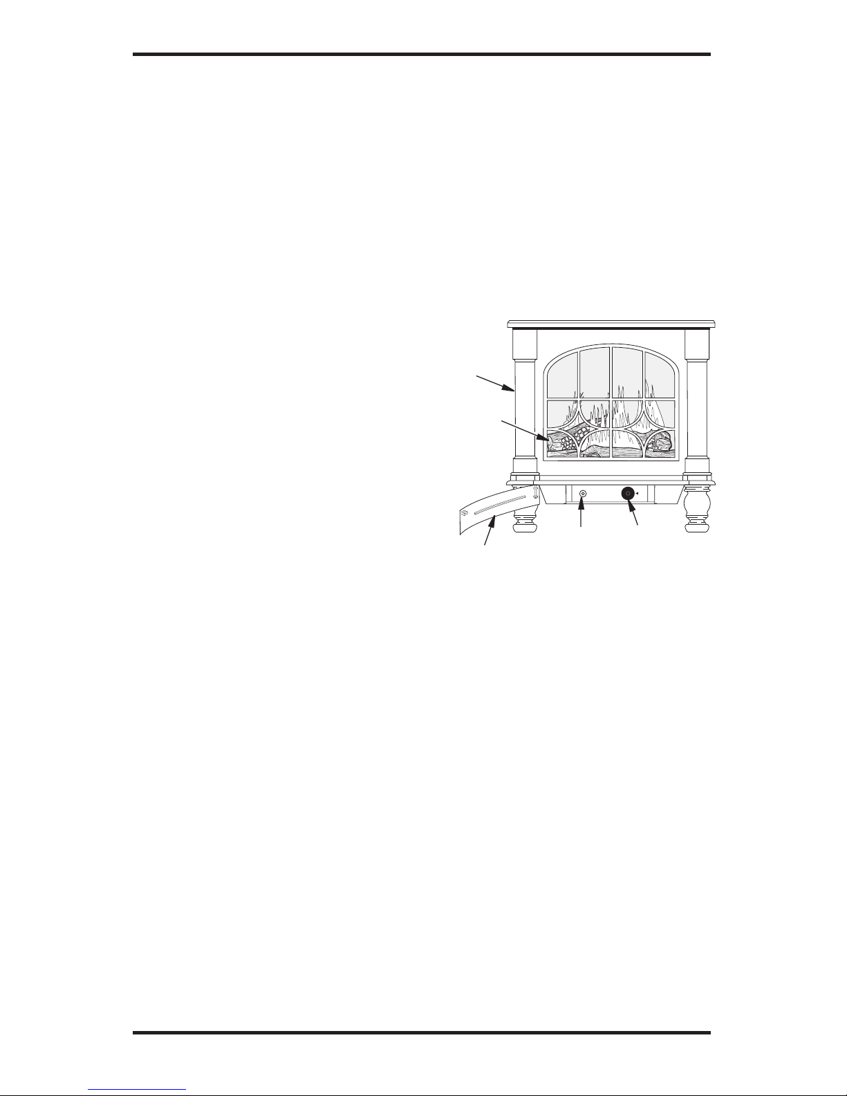
PRODUCT
IDENTIFICATION
Figure 1 - Typical Stove Cabinet Model
with Comfort Glow Gas Log Heater
Stove
Body
Stove Door (Shown
in the open position)
Piezo
Ignitor
Control
Knob
One Piece
Log Set
Inside Stove
Cavity
LOCAL CODES
Install and use heater with care. Follow all local
codes. In the absence of local codes, use the latest edition of The National Fuel Gas Code ANSI
Z223.1/NFPA 54*.
*Available from:
American National Standards Institute, Inc.
1430 Broadway
New York, NY 10018
National Fire Protection Association, Inc.
Batterymarch Park
Quincy, MA 02269
www.desatech.com
115580-01A 5
PRODUCT FEATURES
OPERATION
This heater is clean burning. It requires no outside
venting. There is no heat loss out a vent or up a
chimney. Heat is generated by realistic, dancing
yellow flames. This heater is designed for vent-free
operation. State and local codes in some areas
prohibit the use of vent-free heaters.
SAFETY PILOT
This heater has a pilot with an Oxygen Depletion Sensing (ODS) safety shutoff system. The
ODS/pilot is a required feature for vent-free room
heaters. The ODS/pilot shuts off the heater if there
is not enough fresh air.
PIEZO IGNITION SYSTEM
This heater has a piezo ignitor. This system requires no matches, batteries or other sources to
light heater.
AIR FOR COMBUSTION
AND VENTILATION
WARNING: This heater shall
not be installed in a confined
space or unusually tight construction unless provisions are
provided for adequate combus
tion and ventilation air. Read the
following instructions to insure
proper fresh air for this and
other fuel-burning appliances
in your home.
Todayʼs homes are built more energy efficient
than ever. New materials, increased insulation and
new construction methods help reduce heat loss
in homes. Home owners weather strip and caulk
around windows and doors to keep the cold air out
and the warm air in. During heating months, home
owners want their homes as airtight as possible.
While it is good to make your home energy effi
cient, your home needs to breathe. Fresh air must
enter your home. All fuel-burning appliances need
fresh air for proper combustion and ventilation.
Exhaust fans, fireplaces, clothes dryers and fuel
burning appliances draw air from the house to
operate. You must provide adequate fresh air for
these appliances. This will insure proper venting
of vented fuel-burning appliances.
PROVIDING ADEQUATE
VENTILATION
The following are excerpts from National Fuel
Gas Code, ANSI Z223.1/NFPA 54, Section 5.3, Air
for Combustion and Ventilation.
All spaces in homes fall into one of the three fol
-
lowing ventilation classifications:
1. Unusually Tight Construction
2. Unconfined Space
3. Confined Space
The information on pages 5 through 7 will help
you classify your space and provide adequate
ventilation.
Unusually Tight Construction
The air that leaks around doors and windows
may provide enough fresh air for combustion and
ventilation. However, in buildings of unusually
tight construction, you must provide additional
fresh air.
Unusually tight construction is defined as
construction where:
a. walls and ceilings exposed to the out
side atmosphere have a continuous
water vapor retarder with a rating of one
perm (6 x 10-11 kg per pa-sec-m2) or less
with openings gasketed or sealed and
b. weather stripping has been added on
openable windows and doors and
c. caulking or sealants are applied to areas
such as joints around window and door
frames, between sole plates and floors,
between wall-ceiling joints, between
wall panels, at penetrations for plumb
ing, electrical and gas lines and at other
openings.
If your home meets all of the three criteria
above, you must provide additional fresh
air. See Ventilation Air From Outdoors
,
page 7.
If your home does not meet all of the
three criteria above, proceed to
Determin-
ing Fresh-Air Flow For Heater Location
,
page 6.

www.desatech.com
115580-01A
6
Confined and Unconfined Space
The National Fuel Gas Code ANSI Z223.1/NFPA
54 defines a confined space as a space whose
volume is less than 50 cubic feet per 1,000 Btu
per hour (4.8 m
3
per kw) of the aggregate input
rating of all appliances installed in that space and
an unconfined space as a space whose volume is
not less than 50 cubic feet per 1,000 Btu per hour
(4.8 m
3
per kw) of the aggregate input rating of
all appliances installed in that space. Rooms com
municating directly with the space in which the
appliances are installed*, through openings not
furnished with doors, are considered a part of the
unconfined space.
* Adjoining rooms are communicating only if
there are doorless passageways or ventilation grills
between them.
DETERMINING FRESH-AIR FLOW
FOR HEATER LOCATION
Determining if You Have a Confined or
Unconfined Space
Use this work sheet to determine if you have a
confined or unconfined space.
Space: Includes the room in which you will
install heater plus any adjoining rooms with door
less passageways or ventilation grills between
the rooms.
1. Determine the volume of the space (length x
width x height).
Length x Width x Height = cu. ft. (volume
of space)
Example: Space size 20 ft. (length) x 16 ft.
(width) x 8 ft. (ceiling height) = 2560 cu. ft.
(volume of space)
If additional ventilation to adjoining room is sup
-
plied with grills or openings, add the volume of
these rooms to the total volume of the space.
2. Multiply the space volume by 20 to determine
the maximum Btu/Hr the space can support.
(volume of space) x 20 = (maximum Btu/Hr
the space can support)
Example: 2560 cu. ft. (volume of space) x 20 =
51,200 (maximum Btu/Hr the space can support)
AIR FOR COMBUSTION
AND VENTILATION
Continued
3. Add the Btu/Hr of all fuel burning appliances
in the space.
Vent-free heater _________
Btu/Hr
Gas water heater* _________
Btu/Hr
Gas furnace ________
Btu/Hr
Vented gas heater ________
Btu/Hr
Gas fireplace logs ________
Btu/Hr
Other gas appliances* + ________
Btu/Hr
Total = ________
Btu/Hr
* Do not include direct-vent gas appliances.
Direct-vent draws combustion air from the
outdoors and vents to the outdoors.
Example:
Gas water heater ________
Btu/Hr
Vent-free heater + ________
Btu/Hr
Total = ________
Btu/Hr
4. Compare the maximum Btu/Hr the space can
support with the actual amount of Btu/Hr used.
_____________Btu/Hr (maximum the space
can support)
___________ Btu/Hr (actual amount of
Btu/Hr used)
Example: 51,200 Btu/Hr (maximum the
space can support)
70,000 Btu/Hr (actual amount
of Btu/Hr used)
The space in the above example is a confined space
because the actual Btu/Hr used is more than the maxi
mum Btu/Hr the space can support. You must provide
additional fresh air. Your options are as follows:
A. Rework worksheet, adding the space of an
adjoining room. If the extra space provides an
unconfined space, remove door to adjoining
room or add ventilation grills between rooms. See
Ventilation Air From Inside Building, page 7.
B. Vent room directly to the outdoors. See Ven
-
tilation Air From Outdoors,
page 7.
C. Install a lower Btu/Hr heater, if lower Btu/Hr
size makes room unconfined.
If the actual Btu/Hr used is less than the
maximum Btu/Hr the space can support,
the
space is an unconfined space. You will need
no additional fresh air ventilation.
40,000
30,000
70,000
www.desatech.com
115580-01A 7
AIR FOR COMBUSTION
AND VENTILATION
Continued
WARNING: If the area in
which the heater may be oper
ated is smaller than that defined
as an unconfined space or if the
building is of unusually tight
construction, provide adequate
combustion and ventilation air
by one of the methods described
in the National Fuel Gas Code,
ANSI Z223.1/NFPA 54, Section
5.3 or applicable local codes.
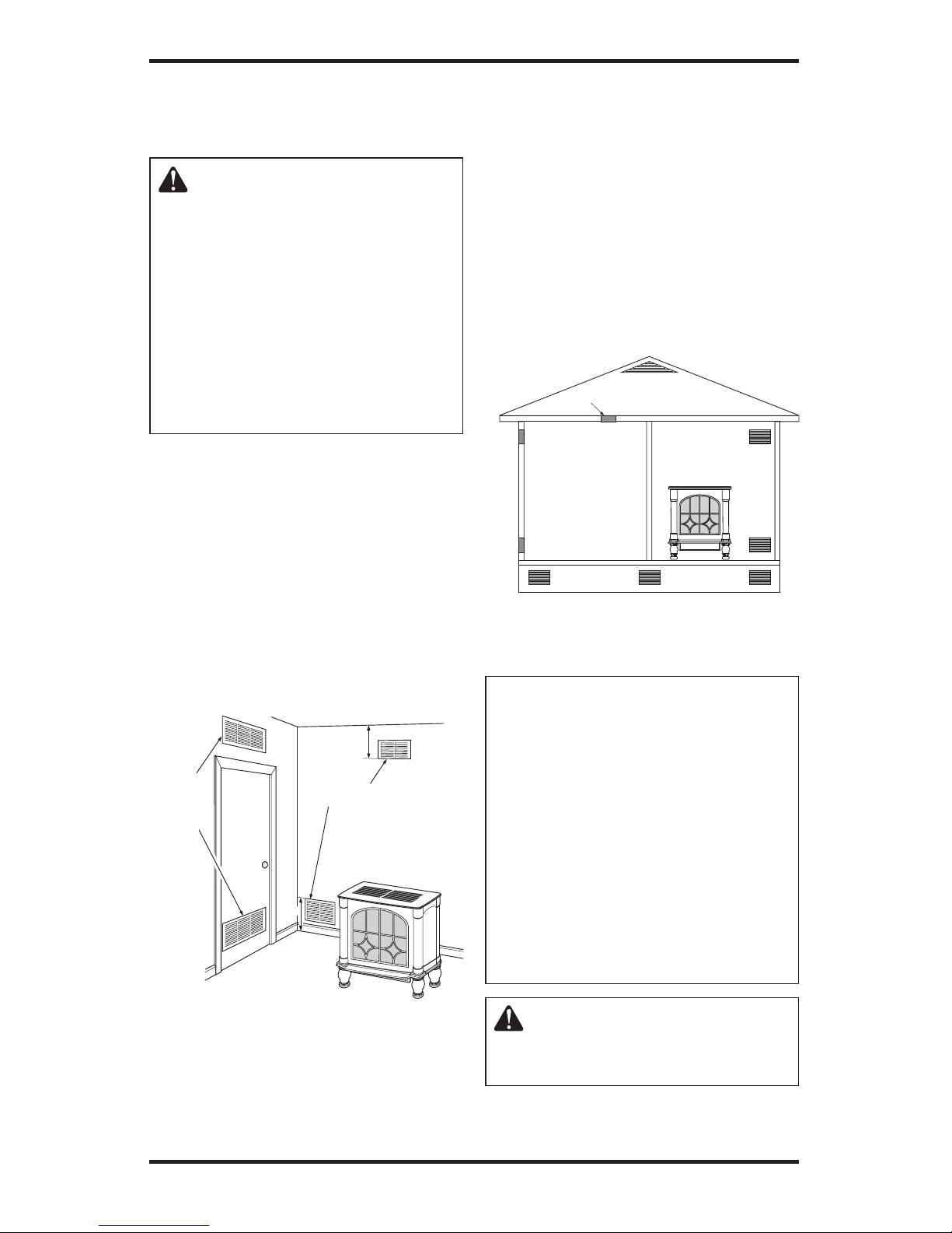
VENTILATION AIR
Ventilation Air From Inside Building
This fresh air would come from an adjoining unconfined space. When ventilating to an adjoining
unconfined space, you must provide two permanent openings: one within 12" of the ceiling and
one within 12" of the floor on the wall connecting
the two spaces (see options 1 and 2, Figure 2). You
can also remove door into adjoining room (see
option 3, Figure 2). Follow the National Fuel Gas
Code, ANSI Z223.1/NFPA 54, Section 5.3, Air for
Combustion and Ventilation for required size of
ventilation grills or ducts.
INSTALLATION
NOTICE: This heater is intended
for use as supplemental heat.
Use this heater along with your
primary heating system. Do not
install this heater as your pri
mary heat source. If you have a
central heating system, you may
run system’s circulating blower
while using heater. This will help
circulate the heat throughout the
house. In the event of a power
outage, you can use this heater
as your primary heat source.
WARNING: A qualified service person must install heater.
Follow all local codes.
Figure 2 - Ventilation Air from Inside
Building
Or
Remove
Door into
Adjoining
Room,
Option
3
Ventilation Grills
Into Adjoining Room,
Option
2
Ve
ntilation
Grills
Into Adjoining
Room,
Option 1
12"
12"
Figure 3 - Ventilation Air from Outdoors
Outlet
Air
Ve
ntilated
Attic
Outlet
A
ir
Inlet
Air
Inlet Air
Ventilated
Crawl Space
To
Crawl
Space
To Attic
Ventilation Air From Outdoors
Provide extra fresh air by using ventilation grills or
ducts. You must provide two permanent openings:
one within 12" of the ceiling and one within 12"
of the floor. Connect these items directly to the
outdoors or spaces open to the outdoors. These
spaces include attics and crawl spaces. Follow the
National Fuel Gas Code, ANSI Z223.1/NFPA 54,
Section 5.3, Air for Combustion and Ventilation for
required size of ventilation grills or ducts.
IMPORTANT: Do not provide openings for inlet
or outlet air into attic if attic has a thermostatcontrolled power vent. Heated air entering the attic
will activate the power vent.
www.desatech.com
115580-01A
8
WARNING: Never install the
heater
• in a bedroom or bathroom
• in a recreational vehicle
• where curtains, furniture,
clothing or other flammable
objects are less than 42 inches
from the front, top or sides of
the heater
• in high traffic areas
• in windy or drafty areas
CAUTION: This heater creates
warm air currents. These currents
move heat to wall surfaces next
to heater. Installing heater next
to vinyl or cloth wall coverings or
operating heater where impurities
(such as, but not limited to, tobacco smoke, aromatic candles,
cleaning fluids, oil or kerosene
lamps, etc.) in the air exist, may
discolor walls or cause odors.
IMPORTANT: Vent-free heaters add moisture to
the air. Although this is beneficial, installing heater
in rooms without enough ventilation air may cause
mildew to form from too much moisture. See Air
for Combustion and Ventilation
, page 5.
CHECK GAS TYPE
Use only the correct gas type (natural or propane/LP)
for your unit. If your gas supply is not correct, do not
install heater. Call dealer where you bought heater
for proper type heater.
WARNING: This appliance
is equipped for (natural or pro
pane/LP) gas. Field conversion
is not permitted.
INSTALLATION
Continued
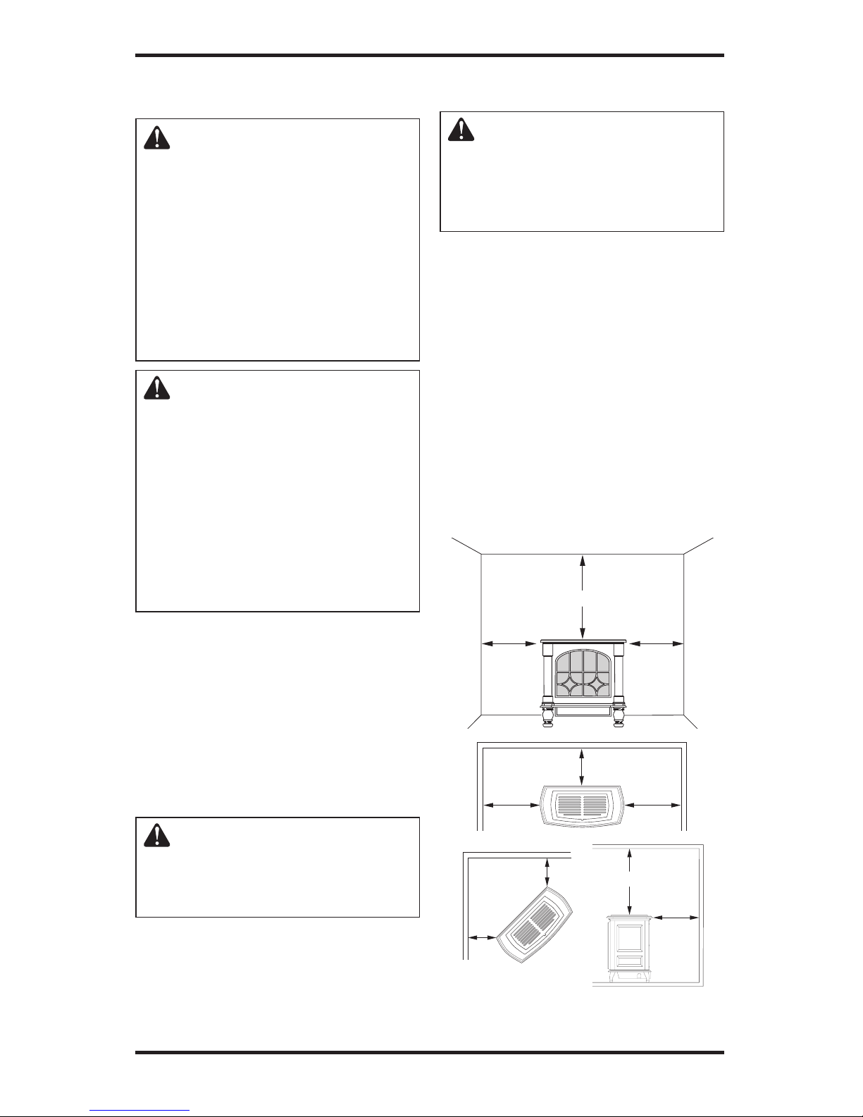
CLEARANCES TO COMBUSTIBLES
(Vent-Free Operation Only)
WARNING: Maintain the
minimum clearances. If you can,
provide greater clearances from
floor, ceiling and adjoining side
and back walls.
Carefully follow the instructions below. This stove
is a freestanding unit designed to set directly on the
floor. IMPORTANT: You must maintain minimum
wall and ceiling clearances during installation.
The minimum clearances are shown in Figure 4.
Measure from outermost point of stove top.
Minimum Wall and Ceiling Clearances
(see Figure 4)
A. Clearances from outermost point of stove top
to any combustible side wall should not be
less than 12 inches.
B. Clearances from outermost point of stove top
to any combustible back wall should not be less
than 6 inches (includes corner installations).
C. Clearances from the stove top to the ceiling
should not be less than 48 inches.
12"
Minimum
12"
Minimum
48"
Minimum
Ceiling
Side Wall Side Wall
Back Wall
Side Wall Side Wall
12 "
Minimum
12 "
Minimum
6 "
Minimum
Corner
Wa
ll
Wa
ll
6 "
Minimum
6 "
Minimum
6"
Minimum
48"
Minimum
Ceiling
Floor
Back
Wall
Figure 4 - Minimum Clearance to Walls
and Ceiling (Stove May Vary Depending
on Model)
www.desatech.com
115580-01A 9
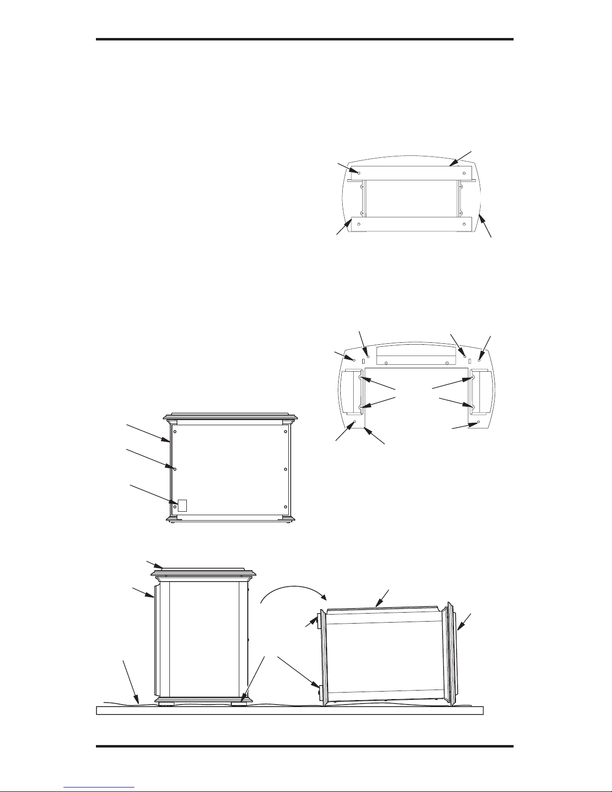
STOVE CAVITY ASSEMBLY
1. Lift off corrugated box enclosing stove
body crating.
2. Remove all screws fastening the wood frame
enclosure. Spread wood frame open and lift
away from plastic-bagged stove body. The
bottom pieces of pallet wood will remain
bolted to the stove body.
3. Remove plastic bag from stove body.
4. Remove back panel from stove (see Figure 5).
Use an adjustable wrench or a 10 mm socket.
Remove six (6) bolts and washers. Keep bolts
and washers to reattach back panel later.
5. Remove all contents from inside stove cavity.
Contents include:
(1) - Stove bottom
(4) - Legs (Amity models include leg
leveler bolts)
(1) - Bottom door
(1) - Top grate
(1) - Hardware kit bag with fasteners
6. Carefully lay stove body on back to attach bottom
components to stove body (see Figure 6). Rest
stove on drop cloth or blanket to avoid scratching
stove edges.
INSTALLATION
Continued
Figure 5 - Removing Back Panel
Bolt
Product
Identification
Label
Back Stove
Panel
Figure 6 - Laying Down Stove On Side (Stove Style May Vary Depending on Model)
Front of
Stove
Unit
Pallet Wood
Bolted to
Stove Body
Bottom
Top of
Stove Unit
Front of Stove
Unit
Top of
Stove
Unit
Drop Cloth/
Blanket
7. Remove remaining pallet wood attached to
bottom of stove body (see Figure 7). Use an
adjustable wrench to remove bolts.
8. Fasten each leg to stove with four (4) bolts.
Use a flat screw driver to tighten bolt to leg.
Thread bolt in tapped holes on stove body (see
Figure 8 and Figure 9, page 10).
Figure 7 - Removing Pallet Wood From
The Bottom of The Stove
Pallet
Wood
Bolt
Bottom Of
Stove Unit
Front
Pallet
Wood
Figure 8 - Locating Threaded Holes
for Stove Bottom, Legs and Door
Attachment (Appearance May Vary
Depending on Model)
Leg
Hole
Leg
Hole
Leg
Hole
Leg Hole
Door Hinge
Step Bolt Hole
Door Catch Bolt
With Adjustable
Hex Nuts Hole
Stove
Bottom
Holes
Front
Bottom Of Stove Unit
 Loading...