

Page 1
GMC11FC/GMC12UC Hardwood
and GMC13FC Oak
Cabinet Mantel
Assembly and Installation Instructions
Firebox
Perimeter Brass
Trim included
with this
Shown with Optional
Hearth Base
Mantel
W ARNING
WARNING ICON G 001
Carefully remove each mantel piece one at a time from shipping carton. Do not
try to lift all of the parts out of the box at once. This may damage mantel pieces.
IMPORTANT:
This mantel is only approved for use with CGFP28 and LFP33 series natural gas and propane fireplace systems,
CGFB32 series fireboxes, and direct-vent gas fireplace systems CDV34 and CHD34 series. Do not use mantel with any
other product. Several optional accessories are available for this mantel kit. These accessories include the GC3333F
and G3334U series hearth base kits for hardwood mantels and GC3335FB series for oak mantels. Contact dealer to
purchase optional accessories.
This mantel kit contains the following pieces:
Hardware 101472-01 101472-01 101472-01
Brass Trim Kit 102753-01 102753-01 102753-01
Trim Kit Hardware 102865-01 102865-01 102865-01
Mounting Blocks 101477-09 101477-09 101477-09
Read entire instruction sheet before assembling or installing mantel kit.
GMC11FC GMC12UC GMC13FC
The hardware package contains the following:
•15 - 1 1/4" wood screws
•Colored finishing nails
Tools required
•#2 Phillips screw driver •Pencil
•Flat head screw driver •Drill
•Measuring tape
If any of these pieces are missing or damaged, contact the dealer where you purchased
this kit or call DESA International’s Parts
Department at 1-800-972-7879 for referral
information.
Page 2
GMC11FC, GMC12UC, and GMC13FC Mantels
Assembly and Installation Instructions
W ARNING
WARNING ICON G 001
Use care when finishing an unfinished mantel. Do not finish mantel pieces near running heater or open flame.
Vapors from most finishing products are highly flammable. Follow manufacturer’s guidelines when using finishing
products.
IMPORTANT:
If you are painting an unfinished mantel, apply an oil base undercoat to the mantel before painting. This will seal the
wood. After undercoat dries completely, lightly sand and apply an oil base top coat. If you do not apply an oil base undercoat and
topcoat, the wood grain will bleed through the paint.
Unpacking Mantel
W ARNING
WARNING ICON G 001
Carefully remove each mantel piece one at a time from
shipping carton. Do not try to lift all of the parts out of
the box at once. This may damage mantel pieces.
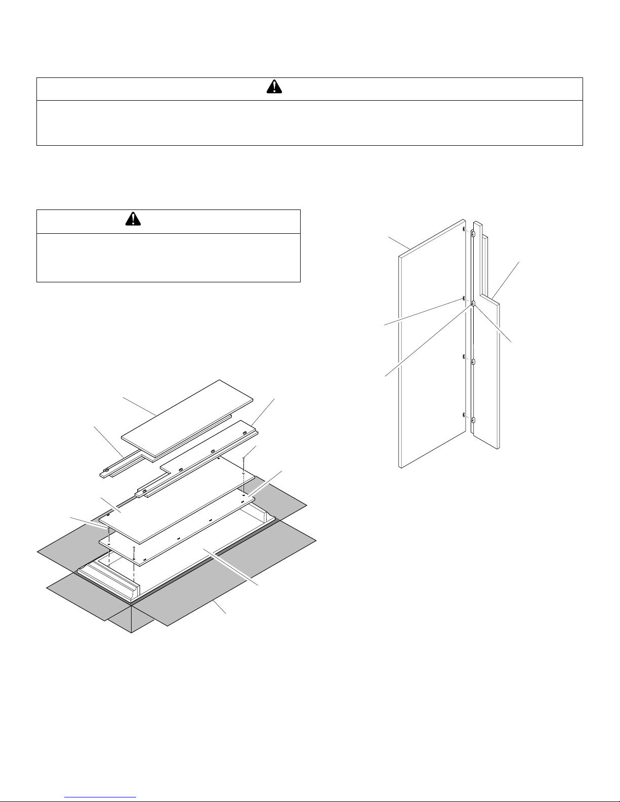
1. Carefully remove packaging materials, header, right front,
and left front one at a time from shipping carton.
2. Remove 2 screws attaching left side to right side (see Figure
1). Remove one side from shipping carton. Discard screws.
Remove 2 screws attaching other side to top. Discard screws.
Remove other side from shipping carton.
3. Remove top from shipping carton.
Header
Left Front
Right Front
Screw
Right Side
Male
Twistlock
Fastener
Screw
Right
Front
Female
Twistlock
Fastener
Side
Screw
Figure 1 - Removing Mantel Pieces from Shipping Carton
Assembling Mantel
1. If you must install mantel flush with wall, baseboard will
prevent proper installation of mantel. Either alter baseboard
to fit mantel or remove baseboard.
2. Insert male twistlock fasteners (located on right side) in
female twistlock fasteners (located on right front) (see Figure
2). Tighten screws of twistlock fasteners one-half turn with
flat head screwdriver. Repeat for left side. This will lock the
fasteners together.
Side
Top
Shipping Carton
Figure 2 - Attaching Mantel Right Front to Mantel Right Side
3. Rest header on face boards of right and left sides (see Figure
3). Push sides together to eliminate gaps with header. Push
down on header to ensure a tight fit (see Figure 4). Attach
header to right side with two 1 1/4" screws. Repeat for other
side (see Figure 4).
4. Place one mounting block on back of one of the side face
boards and the front panel. Attach mounting block to front
panel and to side face board with two 1 1/4" screws (see
Figure 4). Repeat for other side.
5. Place top on assembly (see Figure 5).
Make sure molding on top fits properly over front and side
panels. Back edge of top should be flush with back edge of
sides. From backside of mantel, locate predrilled holes near
top of left side. Attach with three 1 1/4" wood screws (see
Figure 6). Repeat above steps to attach top to right side.
Locate predrilled hole near the center of the header. Attach
the header to the top using one 1 1/4" wood screw.
Note:
If using optional hearth base with mantel, move hearth
base to installation location. If using mantel without optional
hearth base, move mantel to installation location.
2
105609
Page 3

Face Boards
Left
Side
Side
Header
Right
Side
Top
Header
Side Face
Boards
Header
Mounting
Block
Figure 3 - Installing Header
Side
1 1/4"
Wood
Screws
1 1/4"
Wood
Screws
Figure 5 - Placing Mantel Top on Mantel Assembly
Top
1 1/4" Wood Screws
Side
Header
Figure 6 - Attaching Top
W ARNING
WARNING ICON G 001
A qualified service person must install gas piping to
heater. Follow all local codes.
Figure 4 - Attaching Header
105609
6. Place mantel in desired location. Place firebox in front
opening of mantel. To make firebox fit through mantel
opening, bend back or remove nailing flanges on sides of the
firebox. Make sure all pieces fit properly. Remove mantel.
Follow instructions included with heater or base to attach to
floor.
7. Mark floor or wall for gas line entrance. Make sure there is
enough clearance between heater and mantel for gas line.
IMPORTANT:
Make sure there are no electrical lines where
gas piping will go through floor or wall.
Continued
3
Page 4

8. From gas meter or propane tank, run hard piping to manual
shutoff valve. You must install the manual shutoff valve
within reach from heater. Install an approved flex hose (if
allowed by local or state codes) for natural or propane gas to
run from the manual shutoff valve to heater.
9. Connect heater to gas line according to instructions in heater
owner’s manual. Check all connections for leaks from heater
to gas meter or propane tank.
WARNING
WARNING ICON G 001
Never use an open flame to check for a leak. Apply a
mixture of liquid soap and water to all joints. Bubbles
forming show a leak. Correct all leaks at once.
10.After firebox is secured, replace mantel. Assemble and install
brass trim.
Assembling and Installing Brass Trim
1. Remove packaging from three pieces of brass trim.
2. Locate 2 adjusting plates with set screws and 2 shims in the
hardware packet.
3. Align shim under adjusting plate as shown in Figure 7.
4. Slide one end of adjusting plate/shim in slot on mitered edge
of top brass trim (see Figure 7).
5. Slide other end of adjusting plate/shim in slot on mitered
edge of side brass trim (see Figure 7).
6. While firmly holding edges of brass trim together, tighten both
screws on the adjusting plate using a slotted screwdriver.
7. Repeat steps 1 through 6 for other side.
Side Brass
Trim
Set Screws
Adjusting
Plate
Top Brass Trim
8. Locate seven hanging shoulder screws in hardware packet.
Tighten the seven hanging shoulder screws (#10-16x.50 long
with .12 shoulder) into holes on firebox sides. Place the
assembled trim onto firebox cabinet. Align hanging notches
on trim with hanging screws on side of firebox (see Figure 8).
Tap trim firmly into place with palm of hand engaging
hanging notches around shoulder screws. Start at one end of
the trim and work around firebox until all notches are fully
engaged.
Trim Hanging
Shoulder Screws
Assembled
Brass Trim
Hanging
Notches
on Trim
Figure 8 - Assembling Brass Trim
Shoulder
Screw
Hanging
Notches
on Trim
Shim
Mitered Edge
Slot
Figure 7 - Assembling Brass Trim
Slot
2701 Industrial Drive
P .O. Box 90004
Bowling Green, KY 42102-9004
Technical Service Department 1-800-323-5190
Parts Department 1-800-972-7879
105609-01
Rev. A
02/99
 Loading...