

Comfort Glow CGFB32CA Circulating Louvered Safety Information And Installation Manual
For more information, visit www.desatech.com
For more information, visit www.desatech.com
CGFB32CA
Circulating
Louvered
Model
UNVENTED (VENT-FREE)
UNIVERSAL FIREBOX
SAFETY INFORMATION AND
INSTALLATION MANUAL
Shown with optional cabinet
mantel, hearth base.
WARNING: If the information in this manual is not
followed exactly, a fire or explosion may result causing property damage, personal injury or loss of life.
Carefully review the instructions supplied with the
decorative type unvented room heater for the minimum fireplace size requirement.
Do not install an appliance in this firebox unless this
firebox meets the minimum dimensions required for
the installation.
This firebox has been tested and approved by CSA
under ANSI Z21.91 for use with any ANSI Z21.11.2
approved gas logs.
This appliance may be installed in an aftermarket*, permanently located, manufactured
(mobile) home, where not prohibited by local codes.
This appliance is only for use with the type of gas indicated on the rating plate. This appliance
is not convertible for use with other gases.
*Aftermarket: Completion of sale, not for purpose of resale, from the manufacturer
WARNING: Improper installation,
adjustment, alteration, service, or
maintenance can cause injury or
property damage. Refer to this
manual for correct installation and
operational procedures. For assistance or additional information consult a qualified installer, service
agency, or the gas supplier.
WARNING: For use only with a listed
gas-fired unvented decorative room
heater. Not to exceed 40,000 Btu/H.
Do not build a wood fire.
Save this manual for future reference.
Save this manual for future reference.
TABLE OF CONTENTS
SAFETY INFORMATION
2
TABLE OF CONTENTS
SAFETY INFORMATION ............................................................ 2
LOCAL CODES........................................................................... 3
UNPACKING............................................................................... 3
PRODUCT SPECIFICATIONS.................................................... 3
PRODUCT FEATURES .............................................................. 4
LOCATING FIREBOX ................................................................. 4
AIR FOR COMBUSTION AND VENTILATION ........................... 4
INSTALLATION ........................................................................... 6
SAFETY INFORMATION
WARNINGS
IMPORTANT: Read this owner’s manual carefully and
completely before trying to assemble, operate, or
service this firebox. Improper use of this firebox can
cause serious injury or death from burns, fire, explosion, electrical shock, or carbon monoxide poisoning.
WARNING: Any change to this firebox or its
controls can be dangerous.
WARNING: Do not allow fans to blow directly into the
firebox. Avoid any drafts that alter burner flame patterns.
Ceiling fans can create drafts that alter burner flame
patterns. Altered burner patterns can cause sooting.
WARNING: Do not use a blower insert, hood, heat
exchanger insert, or other accessory not approved
for use with this heater.
Due to high temperatures, the firebox should be
located out of traffic and away from furniture and
draperies.
Do not place clothing or other flammable material on
or near firebox. Never place any objects on the firebox or logs.
Firebox front and screen become very hot when
running firebox. Keep children and adults away from
hot surfaces to avoid burns or clothing ignition.
Firebox will remain hot for a time after shutdown.
Allow surfaces to cool before touching.
TECHNICAL SERVICE .............................................................. 11
REPLACEMENT PARTS ........................................................... 11
ILLUSTRATED PARTS BREAKDOWN AND PARTS LIST ....... 12
ACCESSORIES ........................................................................ 14
OWNER’S REGISTRATION FORM.......................................... 15
PARTS CENTRALS .................................................................. 17
WARRANTY INFORMATION ....................................... Back Page
Carefully supervise young children when they are in
the room with firebox.
You must operate this fireplace with the provided
fireplace screen (closed), hood, and brick liner in
place. Make sure these parts are in place before
running firebox.
Keep the firebox area clear and free from combustible materials, gasoline, and other flammable vapors
and liquids.
1. This firebox shall not be installed in a bedroom or bathroom.
2. Never install the firebox
• in a recreational vehicle
• where curtains, furniture, clothing, or other flammable ob-
jects are less than 42 inches from the front, top, or sides of
the firebox
• in high traffic areas
• in windy or drafty areas
3. Do not use this firebox as a wood-burning fireplace. Use only
decorative unvented room heaters (log sets).
4. Do not add extra logs or ornaments such as pine cones, vermiculite, or rock wool. Using these added items can cause sooting.
5. Vent-free gas log heaters installed in these fireboxes require
fresh air ventilation to run properly. See Air for Combustion
and Ventilation, pages 4 through 6.
6. Do not run firebox
• where flammable liquids or vapors are used or stored
• under dusty conditions
7. Do not use this firebox to cook food or burn paper or other objects.
8. Turn firebox off and let cool before servicing. Only a qualified
service person should service and repair firebox.
For more information, visit www.desatech.com
For more information, visit www.desatech.com
107331-01E
SAFETY INFORMATION
35 1/16"
31
3
/4"
1
1
/4"
16
1
/4"
2
3
/4"
3
7
/8"
6 3/4"
2
3
/4"
6
3
/8"
19
3
/8"
1 1/4"
LOCAL CODES
UNPACKING
PRODUCT IDENTIFICATION
3
3
SAFETY INFORMATION
Continued
9. Operating vent-free log sets in a firebox above elevations of
4,500 feet could cause pilot outage.
10. Do not use the firebox if it has been under water due to the
shock hazard that could result with the blower accessary (if
installed) in place.
11. Provide adequate clearances around air openings.
LOCAL CODES
Install and use fireplace with care. Follow all local codes. In the absence
of local codes, use the latest edition of The National Fuel Gas Code ANSI
Z223.1/NFPA 54*. Firebox must be electrically grounded in accordance
with the National Electrical Code, ANSI/NFPA70 (latest edition).
*Available from:
American National Standards Institute, Inc.
1430 Broadway
New York, NY 10018
National Fire Protection Association, Inc.
Batterymarch Park
Quincy, MA 02269
UNPACKING
1. With utility knife, cut the carton all the way around above the
staples on the bottom tray. Lift the carton off the firebox. Remove packing.
2. Check carton contents for the following:
• Screen assembly
• Screen support rod
• Hardware and parts bag containing the following:
- Owner’s Operation and Installation Manual
- 2 - Black #10 x 3/8" Phillips screws
3. If any items are missing, inform dealer where you bought the
firebox.
4. Check all items for any shipping damage. If damaged, promptly
inform dealer where you bought firebox.
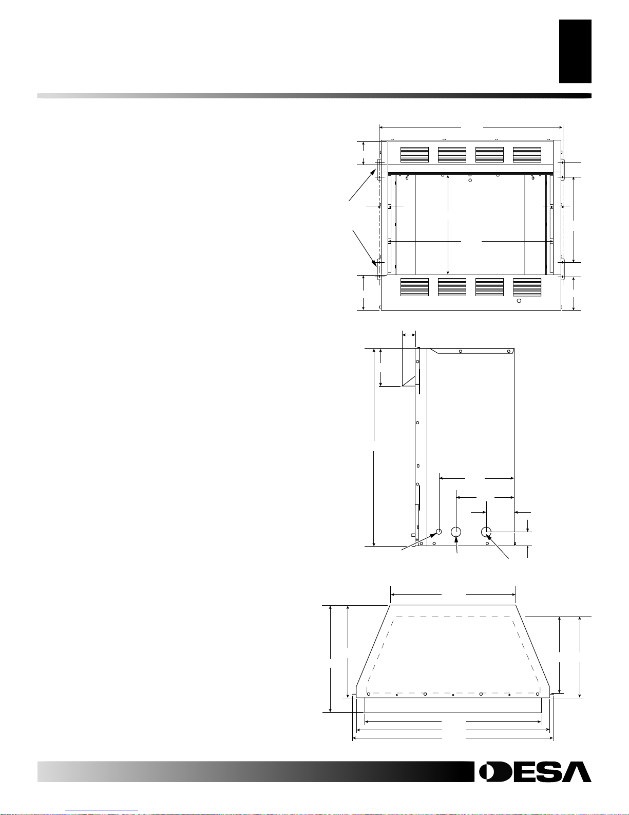
PRODUCT SPECIFICATIONS
Built-in
Nailing
Flanges
Figure 1 - Firebox Front View
6"
11
/16"
33
3
/16"
32
Electrical Access Hole
Figure 2 - Firebox Side View
1
/4"
2
Electrical
Access Hole
22 1/2"
12 1/2"
3
/4"
9
5
4
/8"
Gas Line Access
1
2
/2"
107331-01E
For more information, visit www.desatech.com
For more information, visit www.desatech.com
*
Note:
11
16
/16"
1
/4"
19
14 1/4" is total firebox
cavity depth including brick
liner. 13
1
/4" is depth of flat
floor including brick liner.
31 5/8"
34 3/8"
35 5/8"
13 1/4"
14 1/4"
*
*
Figure 3 - Firebox Top View
PRODUCT FEATURES
4
Operation
Blower Accessory
LOCATING FIREBOX
AIR FOR COMBUSTION AND VENTILATION
Providing Adequate Ventilation
PRODUCT FEATURES
OPERATION
This firebox is designed to accept unvented decorative gas logs. It
requires no outside venting or chimney making installation easy and
inexpensive. When used without the blower the firebox requires no
electricity making it ideal for emergency backup heat.
BLOWER ACCESSORY
The CGFB32CA firebox will accept the GA3750 accessory. The
variable blower allows you to select the fan speed you desire. The
blower circulates heated air from the firebox into the room. Use of
blower is optional.
LOCATING FIREBOX
Plan where you will install the firebox. This will save time and
money later when you install the firebox. Before installation,
consider the following:
1. Where the firebox will be located. Allow for wall and ceiling
clearances (see Installation Clearances, page 6).
2. Everything needed to complete installation.
3. These models CANNOT be installed in a bedroom or bathroom.
4. Proper air for combustion and ventilation (see below).
AIR FOR COMBUSTION AND
VENTILATION
WARNING: This firebox shall not be installed in a
confined space or unusually tight construction unless provisions are provided for adequate combustion and ventilation air. Read the following instructions to insure proper fresh air for this and other fuelburning appliances in your home.
PROVIDING ADEQUATE VENTILATION
The following are excerpts from National Fuel Gas Code ANSI
Z223.1/NFPA 54, Section 5.3, Air for Combustion and Ventilation.
All spaces in homes fall into one of the three following ventilation
classifications:
1. Unusually Tight Construction
2. Unconfined Space
3. Confined Space
The information on pages 4 through 6 will help you classify your
space and provide adequate ventilation.
Unusually Tight Construction
The air that leaks around doors and windows may provide enough
fresh air for combustion and ventilation. However, in buildings of
unusually tight construction, you must provide additional fresh air.
Unusually tight construction is defined as construction
where:
a. walls and ceilings e xposed to the outside atmosphere
have a continuous water vapor retarder with a rating
of one perm (6x10
openings gasketed or sealed
b. weather stripping has been added on openable win-
dows and doors
c. caulking or sealants are applied to areas such as
joints around window and door frames, between sole
plates and floors, between wall-ceiling joints, between
wall panels, at penetrations for plumbing, electrical,
and gas lines, and at other openings.
If your home meets all of the three criteria above, you
must provide additional fresh air. See
From Outdoors,
If your home does not meet all of the
proceed to
tion
, page 5.
page 6.
Determining Fresh-Air Flow For Firebox Loca-
-11
kg per pa-sec-m2) or less with
and
and
Ventilation Air
three criteria above,
Today’s homes are built more energy efficient than ever. New materials, increased insulation, and new construction methods help reduce
heat loss in homes. Home owners weather strip and caulk around
windows and doors to keep the cold air out and the warm air in. During
heating months, home owners want their homes as airtight as possible.
While it is good to make your home energy efficient, your home
needs to breathe. Fresh air must enter your home. All fuel-burning
appliances need fresh air for proper combustion and ventilation.
Exhaust fans, fireboxes, clothes dryers, and fuel burning appliances
draw air from the house to operate. You must provide adequate fresh
air for these appliances. This will insure proper venting of vented
fuel-burning appliances.
For more information, visit www.desatech.com
For more information, visit www.desatech.com
Confined Space and Unconfined Space
The National Fuel Gas Code ANSI Z223.1/NFPA 54 defines a
confined space as a space whose volume is less than 50 cubic feet
per 1,000 Btu per hour (4.8 m3 per kw) of the aggregate input rating
of all appliances installed in that space and an unconfined space as
a space whose volume is not less than 50 cubic feet per 1,000 Btu per
hour (4.8 m3 per kw) of the aggregate input rating of all appliances
installed in that space. Rooms communicating directly with the
space in which the appliances are installed*, through openings not
furnished with doors, are considered a part of the unconfined space.
* Adjoining rooms are communicating only if there are doorless
passageways or ventilation grills between them.
107331-01E

AIR FOR COMBUSTION
AND VENTILATION
Continued
AIR FOR COMBUSTION AND VENTILATION
Determining Fresh-Air Flow For Heater Location
Ventilation Air
5
5
DETERMINING FRESH-AIR FLOW FOR
HEATER LOCATION
Determining if You Have a Confined or
Unconfined Space
Use this work sheet to determine if you have a confined or unconfined space.
Space: Includes the room in which you will install heater plus any adjoining
rooms with doorless passageways or ventilation grills between the rooms.
1. Determine the volume of the space (length x width x height).
Length x Width x Height =___________ cu. ft. (volume of space)
Example:
height) = 2560 cu. ft. (volume of space)
If additional ventilation to adjoining room is supplied with grills or open-
ings, add the volume of these rooms to the total volume of the space.
2. Multiply the space volume by 20 to determine the maximum Btu/Hr
the space can support.
__________ (volume of space) x 20 = (Maximum Btu/Hr the space
Example:
Btu/Hr the space can support)
3. Add the Btu/Hr of all fuel burning appliances in the space.
* Do not include direct-vent gas appliances. Direct-vent draws combustion air from the outdoors and vents to the outdoors.
4. Compare the maximum Btu/Hr the space can support with the actual
amount of Btu/Hr used.
__________________ Btu/Hr (maximum the space can support)
__________________ Btu/Hr (actual amount of Btu/Hr used)
Example:
The space in the above example is a confined space because the actual Btu/Hr
used is more than the maximum Btu/Hr the space can support. You must
provide additional fresh air. Your options are as follows:
Space size 20 ft. (length) x 16 ft. (width) x 8 ft. (ceiling
can support)
2560 cu. ft. (volume of space) x 20 = 51,200 (maximum
Vent-free heater _____________ Btu/Hr
Gas water heater* _____________ Btu/Hr
Gas furnace _____________ Btu/Hr
Vented gas heater _____________ Btu/Hr
Gas fireplace logs _____________ Btu/Hr
Other gas appliances* + _____________ Btu/Hr
Total = _____________ Btu/Hr
Example:
Gas water heater _____________ Btu/Hr
Vent-free heater + _____________ Btu/Hr
Total = _____________ Btu/Hr
51,200 Btu/Hr (maximum the space can support)
79,000 Btu/Hr (actual amount of Btu/Hr used)
40,000
39,000
79,000
A. Rework worksheet, adding the space of an adjoining room. If the
extra space provides an unconfined space, remove door to adjoining
room or add ventilation grills between rooms. See Ventila tion Air F rom
Inside Building below.
B. Vent room directly to the outdoors. See Ventilation Air F rom Out-
doors, page 6.
C. Install a lower Btu/Hr heater, if lower Btu/Hr size makes room unconfined.
If the actual Btu/Hr used is less than the maximum Btu/Hr the space can
support, the space is an unconfined space. You will need no additional fresh
air ventilation.
WARNING: If the area in which the firebox and gas
log heater may be operated is smaller than that
defined as an unconfined space or if the building is of
unusually tight construction, provide adequate combustion and ventilation air by one of the methods
described in the
NFPA 54 Section 5.3
National Fuel Gas Code, ANSI Z223.1/
or applicable local codes.
VENTILATION AIR
Ventilation Air From Inside Building
This fresh air would come from an adjoining unconfined space.
When ventilating to an adjoining unconfined space, you must
provide two permanent openings: one within 12" of the ceiling and
one within 12" of the floor on the wall connecting the two spaces
(see options 1 and 2, Figure 4). You can also remove door into
adjoining room (see option 3, Figure 4). Follow the National Fuel
Gas Code ANSI Z223.1/NFPA 54, Section 5.3, Air for Combustion
and Ventilation for required size of ventilation grills or ducts.
12"
Ventilation
Grills
Into Adjoining
Room,
Option 1
Or
Remove
Door into
Adjoining
Room,
Option
3
Ventilation Grills
Into Adjoining Room,
Option 2
12"
For more information, visit www.desatech.com
For more information, visit www.desatech.com
107331-01E
Figure 4 - Ventilation Air from Inside Building

AIR FOR COMBUSTION AND VENTILATION
6
Ventilation Air (Cont.)
INSTALLATION
Installation Clearances
AIR FOR COMBUSTION AND
VENTILATION
Continued
Ventilation Air From Outdoors
Provide extra fresh air by using ventilation grills or ducts. You must
provide two permanent openings: one within 12" of the ceiling and
one within 12" of the floor. Connect these items directly to the
outdoors or spaces open to the outdoors. These spaces include attics
and crawl spaces. Follow the National Fuel Gas Code ANSI Z223.1/
NFPA 54, Section 5.3, Air for Combustion and Ventilation for
required size of ventilation grills or ducts.
IMPORTANT:
attic if attic has a thermostat-controlled power vent. Heated air
entering the attic will activate the power vent.
Outlet
Air
Inlet
Air
Figure 5 - Ventilation Air from Outdoors
Do not provide openings for inlet or outlet air into
Outlet
Air
Inlet Air
Ventilated
Attic
To Attic
To
Crawl
Space
Ventilated
Crawl Space
WARNING: Never install the firebox
• in a bedroom or bathroom
• in a recreational vehicle
• where curtains, furniture, clothing, or other flam-
mable objects are less than 42 inches from the
front, top, or sides of the firebox
• in high traffic areas
• in windy or drafty areas
CAUTION: Log heaters installed in this firebox
create warm air currents. These currents move heat
to wall surfaces next to firebox. Installing firebox next
to vinyl or cloth wall coverings or operating firebox
where impurities (such as, but not limited to, tobacco
smoke, aromatic candles, cleaning fluids, oil or kerosene lamps, etc.) in the air exist, may discolor walls
or cause odors.
IMPORTANT:
Vent-free gas log heaters add moisture to the air.
Although this is beneficial, installing firebox in rooms without
enough ventilation air may cause mildew to form from too much
moisture. See Air for Combustion and Ventilation, pages 4 through 6.
IMPORTANT:
Make sure the firebox is level. If firebox is not level,
log set will not work properly.
Note
: Your Comfort Glow firebox is designed to be used in zero
clearance installations. Wall or framing material can be placed
directly against any exterior surface on the rear, sides, or top of your
firebox, except where standoff spacers are integrally attached. If
standoff spacers are attached to your firebox, these spacers can be
placed directly against wall or framing materials.
Use the dimensions shown for rough openings to create the easiest
installation (see Built-In Firebox Installation, page 10).
INSTALLATION
NOTICE: This heater is intended for use as supplemental heat. Use this heater along with your primary
heating system. Do not install this heater as your
primary heat source. If you have a central heating
system, you may run system’s circulating blower
while using heater. This will help circulate the heat
throughout the house. In the event of a power outage,
you can use this heater as your primary heat source.
WARNING: A qualified service person must in-
stall firebox. Follow all local codes.
For more information, visit www.desatech.com
For more information, visit www.desatech.com
INSTALLATION CLEARANCES
WARNING: Maintain the minimum clearances. If
you can, provide greater clearances from floor, ceiling, and adjoining wall.
Carefully follow the instructions below. This will ensure safe
installation.
Minimum Clearances For Side Combustible
Material, Side Wall, and Ceiling
A. Clearances from the side of the fireplace cabinet to any combus-
tible material and wall should follow diagram in Figure 6, page 7.
Example:
combustible material and protrudes 3 1/2" from the wall. This
combustible material must be 4" from the side of the fireplace
opening (see Figure 6, page 7).
B. Clearances from the top of the fireplace opening to the ceiling
should not be less than 42 inches.
The face of a mantel, bookshelf, etc. is made of
107331-01E
 Loading...