

Comfort Company Swing-Clear Lap Tray User Manual
SWING CLEAR LAP TRAY
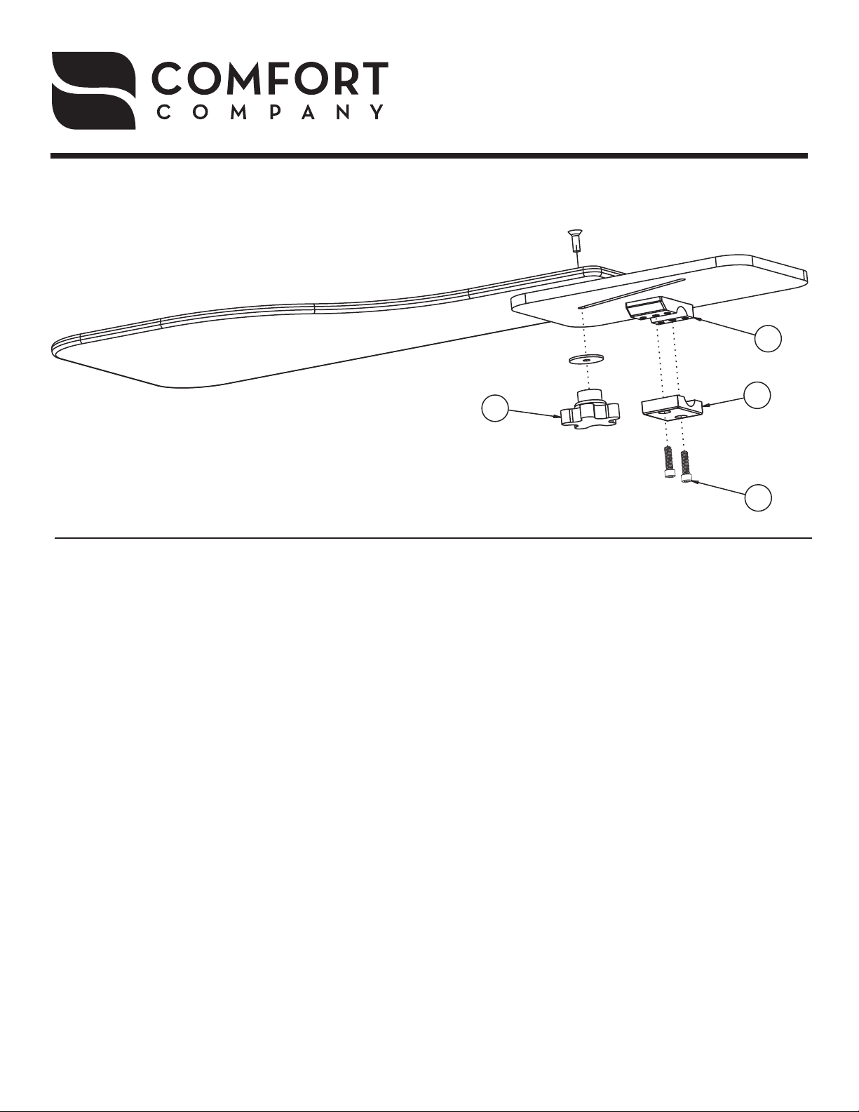
Parts Included:
1 - Swing Clear Lap Tray Assembly
2 - 3/16” Allen Wrench
Toll Free 800.564.9248
www.comfortcompany.com
509 South 22nd Ave Bozeman, MT 59718
C
Remove existing armrest from wheelchair.
1
Remove two screws (A) from bottom clamp
2
(B). Set the top half of the clamp (C) to the
top of the wheelchair arm rail. Then reinstall
the bottom clamp (B) using the screws (A).
Adjustment lever (D) should always be
3
screwed in far enough to securely hold the
assembly together. To adjust, loosen the
lever (D), shift the tray to the desired position, then tighten the lever once again to lock
the tray into position.
D
Attach the mounting bracket (F) to the foam
6
pad assembly (G) using two of the pan head
screws (E). The third screw is provided for
aesthetic purposes.
*NOTE: The provided diagram shows the assembly
instructions for the left side leg rest.
Insert the shoulder bolt (A) into the washer
7
(B), mounting bracket (F) and thread securely
into the interlock cane clamp (C).
*NOTE: The various holes on the mounting bracket
(F) allow for varying foam height mounting.
B
A
Insert the shoulder bolt (A) into the washer
4
(B), mounting bracket (F) and thread securely
into the interlock cane clamp (C).
*NOTE: The various holes on the mounting bracket
(F) allow for varying foam height mounting.
Attach the interlock cane clamp to the leg
5
rest wheelchair tube. For 1” diameter tubes,
use the longer socket head cap screws
provided in the products kit bag.
Attach the interlock cane clamp to the leg
8
rest wheelchair tube. For 1” diameter tubes,
use the longer socket head cap screws
provided in the products kit bag.
Attach the mounting bracket (F) to the foam
9
pad assembly (G) using two of the pan head
screws (E). The third screw is provided for
aesthetic purposes.
*NOTE: The provided diagram shows the assembly
instructions for the left side leg rest.
IS-SWINGCLEARTRAY
REV0413
 Loading...