

Page 1
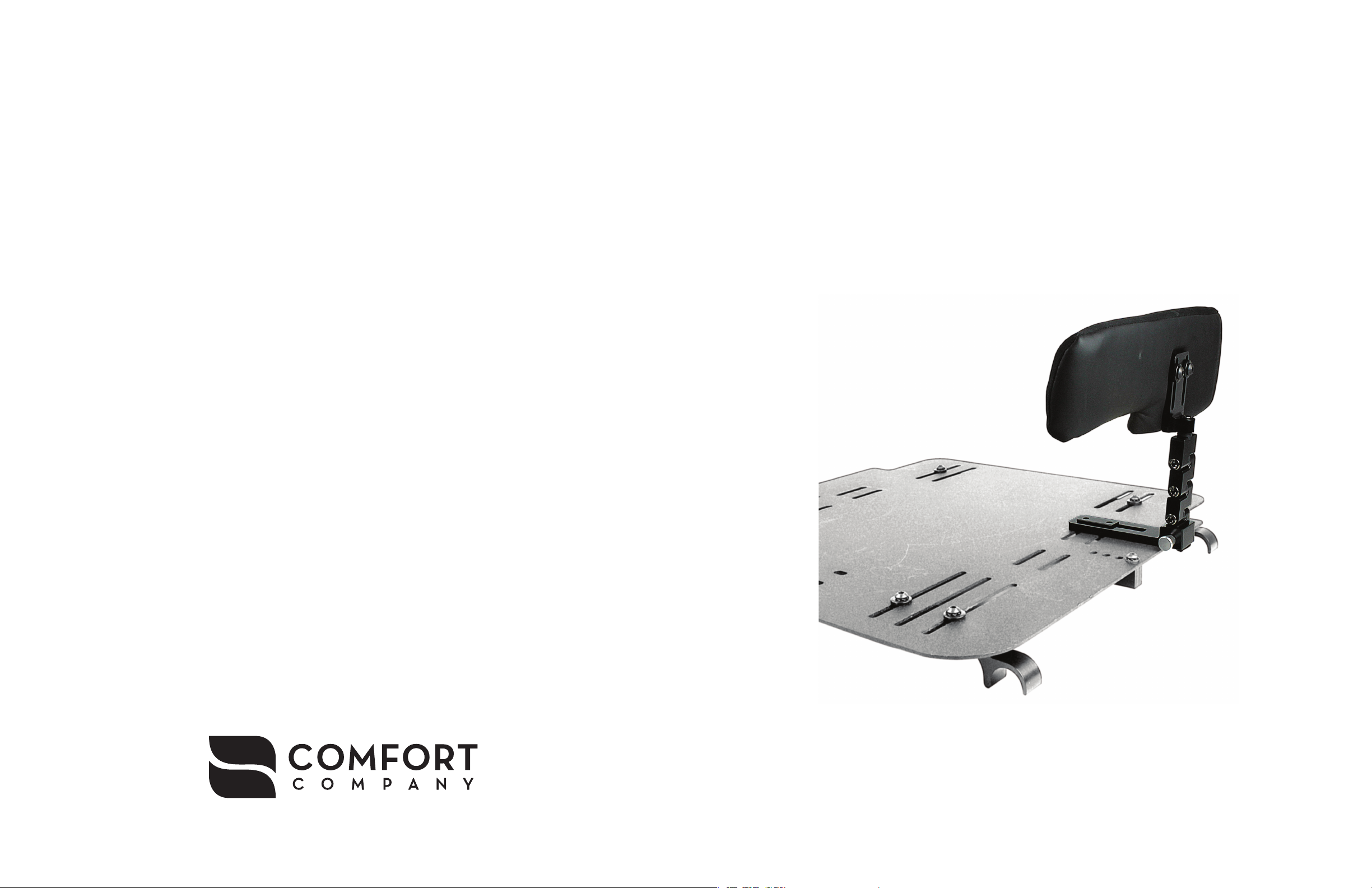
QUICK RELEASE
HIP GUIDE HARDWARE
Toll Free 800.564.9248 www.comfortcompany.com 509 South 22nd Ave Bozeman, MT 59718
www.comfortcompany.com
IS-QRHIPGUIDEHARDWARE
REV0413
Page 2
QUICK RELEASE HIP GUIDE HARDWARE
Parts Included:
1 - Quick Release Hip Guide Hardware Assembly
1 - 5mm Hex Key
1 - 5/32” Hex Key
INITIAL INSTALLATION INSTRUCTIONS
M
J
G
I
N
L
K
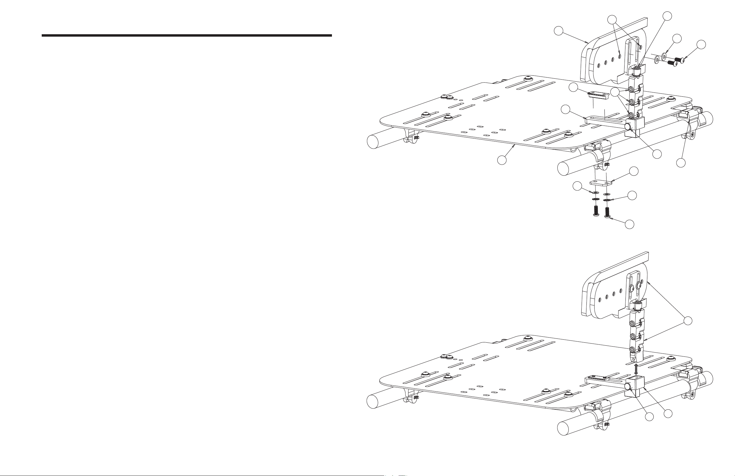
For the easiest method of installation, remove the solid seat pan assembly (A) from the wheelchair using the
1
plastic quick fastening clips (B).
Remove (C), (D), (E), (F), (G) components from hip guide assembly using the 5/32” hex key.
2
Set (H) on top of the solid seat pan at the required width & depth, making sure the slot in the assembly base
3
lines up with two of the seat pan mounting slots as shown in Figure 1. Assembly order: (C), (D), (E), (F), (A),
(H) and (G). Secure tightly using the 5/32” hex key.
Repeat steps 2 and 3 with the mounting bracket on the opposite side.
4
NOTE: Be sure to mount bracket assembly such that bolt heads (I) are facing the front end of the solid seat pan.
Mount hip pad (J) onto hip guide hardware assembly using screws (K) and washers (L) in the desired set of
5
mounting holes (M). Secure tightly using the 5/32” hex key. Be sure to put the foam covered side of the
pad facing inward with the solid wood frame outward and aligned with the mounting bracket.
NOTE: The end of the hip guide with the cutout must face towards the front of the seat pan.
Mounting of hip guide hardware is complete. Be sure to double check all bolts are securely fastened.
H
A
E
FIGURE 1 C
O
B
F
D
ADJUSTMENT INSTRUCTIONS
The hip guide pad (J) can be adjusted forward or backwards. To adjust, remove hip guide pad from the
1
hardware assembly, locate the desired holes (M) along the hip guide pad and burn a new hole(s) through the
cover. Then securely fasten the pad to the hardware assembly with screws (K) and washers (L) using the
5/32” hex key.
Hip guides can be adjusted to different widths, heights and angles by loosening (but not removing) bolts (I)
2
or (N) using the 5mm hex key and adjusting the orientation of the assembly. Make sure to tighten bolts (I)
or (N) tightly after the mounting bracket position has been adjusted.
To use the quick release feature of the hip guide hardware assembly, pull knob (O) and lift hardware assem-
3
bly (P) upwards as shown in Figure 2.
Reattach the hip guide hardware simply by inserting (P) back into (H). Be sure the assembly has fully seated
4
and the knob (O) has fully retracted to secure the assembly.
FIGURE 2
P
O
H
 Loading...