

Comfort Company Lateral Trunk Support User Manual

LATERAL TRUNK
SUPPORTS
Attaching Rigid Lateral Pads
and Swing Away Lateral Pads
Toll Free 800.564.9248 www.comfortcompany.com 509 South 22nd Ave Bozeman, MT 59718
www.comfortcompany.com
IS-LATERALTRUNKSUPPORT
REV0814
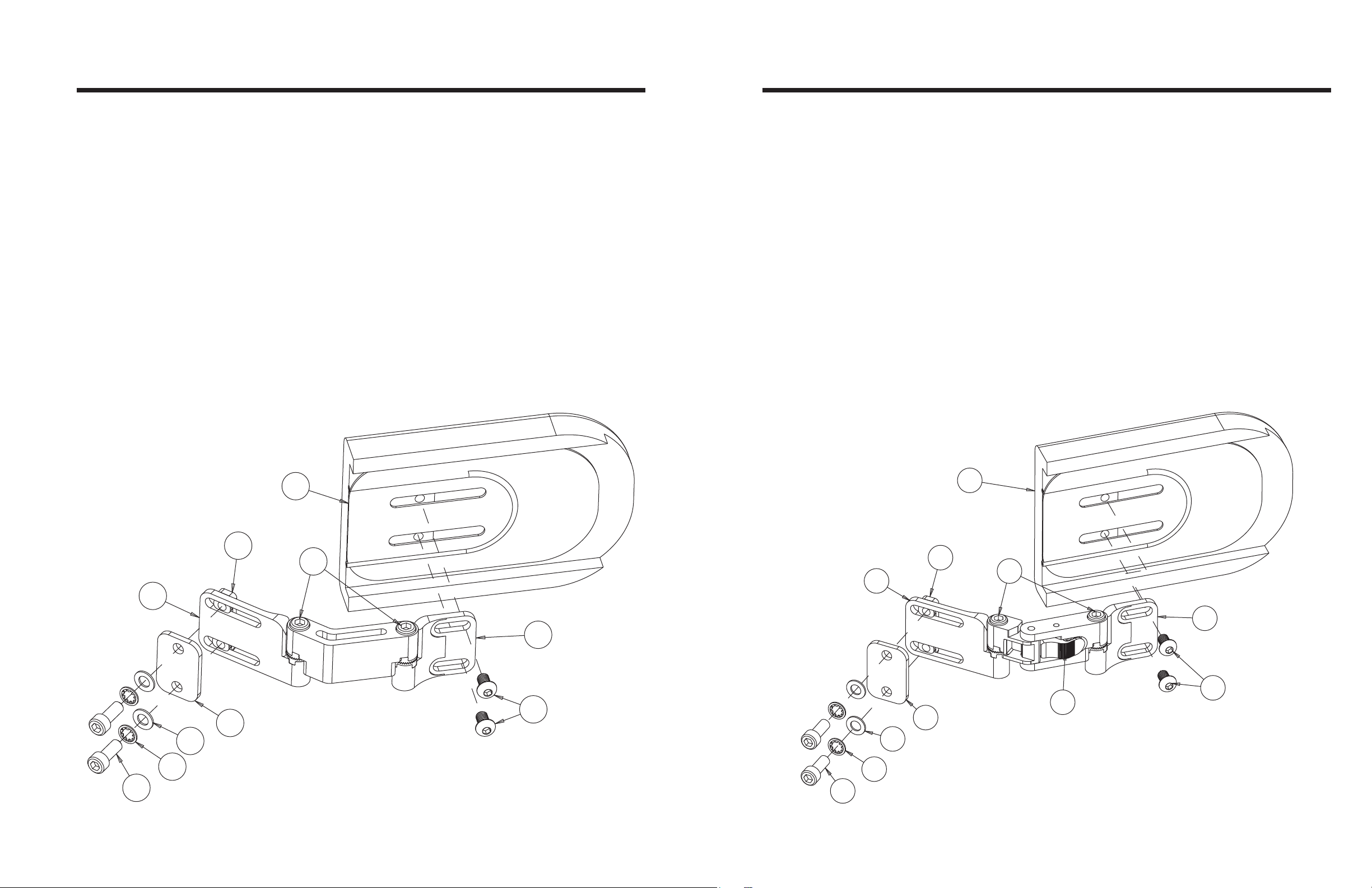
LATERAL TRUNK SUPPORT
SWING AWAY LATERAL TRUNK SUPPORT
Parts Included:
1 - Rigid Lateral Hardware Assembly (LT_-RF) / *Acta-Relief (LT_-RF-K)
1 - 5mm Allen Wrench
1 - 5/32” Allen Wrench
Loosen and remove bolts (A) using the provided 5mm Allen wrench.
1
Fasten the base end of the hardware to the mounting slots on the wheelchair back shell in the order (A-B-C-D-Shell-E-F) as shown in
2
Figure 1. Securely tighten once mounting brackets are in position.
*ACTA-RELIEF - Fasten the base end of the hardware to the outside mounting slots on the shell in the order (A-B-C-D-E-Shell-F) as
shown in Figure 1. Securely tighten once mounting brackets are in position.
To properly position the lateral pad (G), loosen but do not remove bolts (A or H) and slide them along the slots of the mounting brackets
3
(E or I) using the provided 5mm and 5/32” Allen wrench. Securely tighten once mounting brackets are in position.
To adjust the orientation of the mounting brackets (E or I), loosen but do not remove bolts (J) using the provided 5mm Allen Wrench.
4
Securely tighten once mounting brackets are in position.
Figure 1: Right Side Rigid Lateral Trunk Support
Parts Included:
1 - Swing Away Lateral Hardware Assembly (LT_-SF) / *Acta-Relief (LT_-SF-K)
1 - 5mm Allen Wrench
1 - 5/32” Allen Wrench
Loosen and remove bolts (A) using the provided 5mm Allen wrench.
1
Fasten the base end of the hardware to the mounting slots on the wheelchair back shell in the order (A-B-C-D-Shell-E-F) as shown in
2
Figure 2. Securely tighten once mounting brackets are in position.
*ACTA-RELIEF - Fasten the base end of the hardware to the outside mounting slots on the shell in the order (A-B-C-D-E-Shell-F) as
shown in Figure 2. Securely tighten once mounting brackets are in position.
To properly position the lateral pad (G), loosen but do not remove bolts (A or H) and slide them along the slots of the mounting brackets
3
(E or I) using the provided 5mm and 5/32” Allen wrench. Securely tighten once mounting brackets are in position.
To adjust the orientation of the mounting brackets (E or I), loosen but do not remove bolts (J) using the provided 5mm Allen Wrench.
4
Securely tighten once mounting brackets are in position.
To swing away the lateral pad, press swing away lever (K). Assembly will snap back into place when returned to its original position.
5
Figure 2: Right Side Swing Away Lateral Trunk Support
A
E
B
C
D
F
G
J
H
G
F
J
E
I
I
H
K
D
C
B
A
 Loading...