

Comfort Company HIP GUIDE ASSEMBLY Instruction Sheet

HIP GUIDE ASSEMBLY
Toll Free 800.564.9248 www.comfortcompany.com 509 South 22nd Ave Bozeman, MT 59718
www.comfortcompany.com
IS-HIPGUIDE
REV0413
HIP GUIDE ASSEMBLY
Parts Included:
Item Description
A
B
C
D
E
F
G
H
I
J
K
L
Remove solid seat pan assembly from the wheelchair by undoing the plastic fastening clips.
Description Qty. Part Number
Two Hole Nut
Hip Guide Bracket
Two Hole Washer
Washer- 9/32" ID 5/8" OD 1/8"
Washer – External Tooth Lock
Screw- M6 X 1.0 X 16MM Button Head
Screw - M6 X 1.0 X 14MM Button Head
Washer- 0.25" ID, Steel, Black
Padded Hip Guide Mount
Screw- M6 x 1.0 x 12 Socket Head
Wrench: 5/32” Allen
Wrench: 3/16” Allen
2
2
2
4
4
4
4
4
2
6
1
1
425386T
425388_-RGD
425386H
30346
30333
30299
30348T
30267
HG-R_H_D-_-FAB Assembly
30233
30207
30208
1
Set the seat pan on a flat table with the underside facing upwards.
2
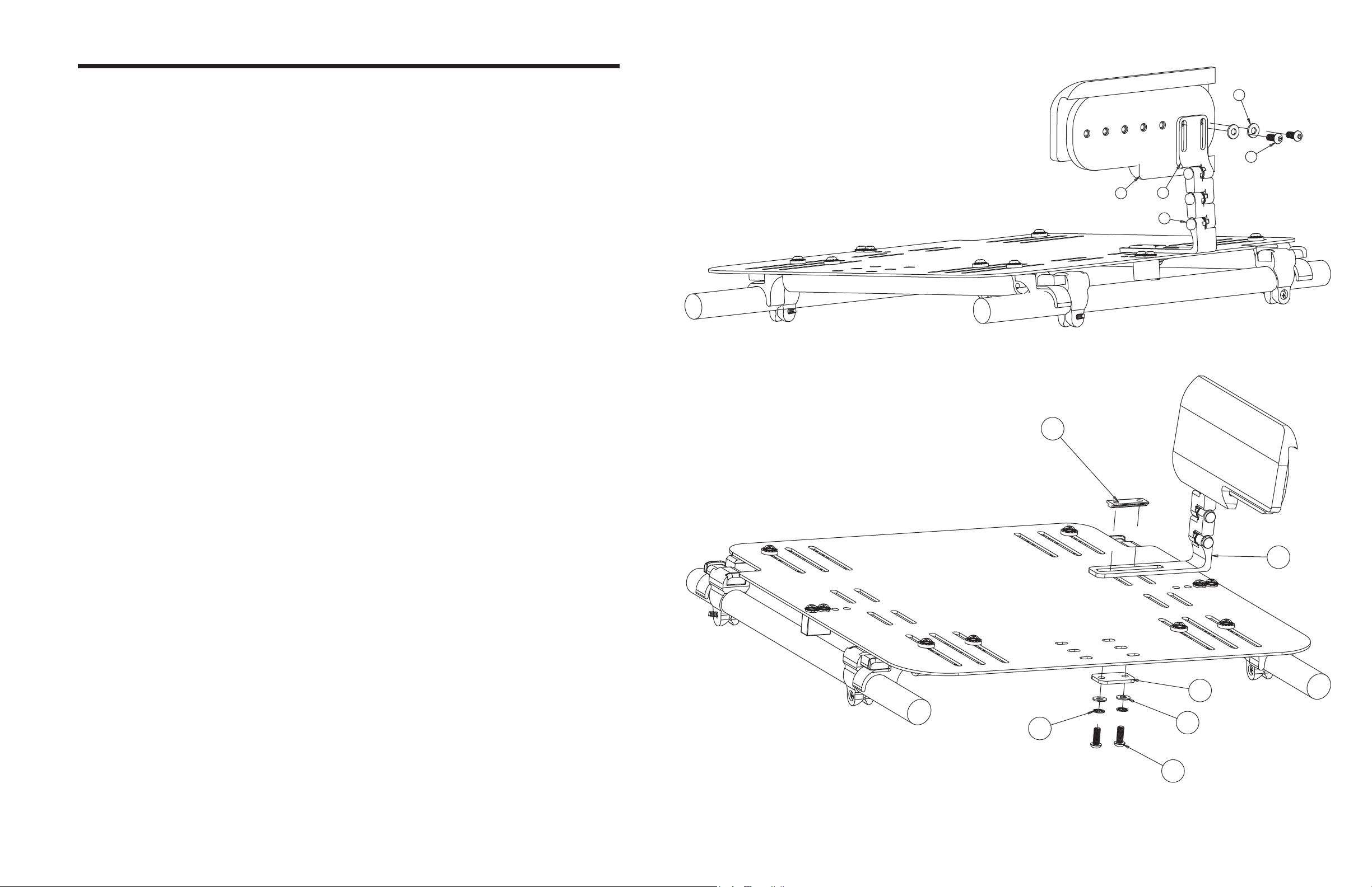
Figure 1
H
G
I
B
J
Remove (F), (E) and (D) from left side (B) assembly that comes in the box.
3
Secure (B) to the solid seat pan by using the slots on either side of the spacer located on the outside edges
4
of the seat pan. Mount (B) with the arm facing upward and the screw head of (F) facing downward.
Assembly order: (F)—(E)—(D)—(C)—SHELL—(B)—(A).
**NOTE- be sure to mount (B) so that (J) on the arm are facing the front end of the solid seat pan and such
that (F) have the button end on the underside of the seat pan. (See Figure 1 and 2 for positioning)
Repeat steps 3 and 4 with the opposite side’s mounting bracket.
5
**NOTE- Be sure to mount (B) such that (J) is facing the front end of the solid seat pan.
Mount (I) onto (B) using (G) and (H). Be sure to put the foam covered side pointing inward with the solid
6
frame outward and aligned with the mounting bracket.
**NOTE—The end of the hip guide with the cutout faces towards the front end of the seat pan.
Repeat step 7 with the opposite side (B) and (I).
7
Hip guides can be adjusted to vary width and height by loosening the six (J) and adjusting the orientation
8
of the assembly. Make sure to tighten (J) snugly after the mounting bracket position has been adjusted.
A
B
C
E
D
Figure 2
F
 Loading...