

Page 1
TRAVELLER SERIES
POWER CHAIR
Use'r Manual
LY-EB103.LY-EB103-N
LY-EB103-S.LY-EB103-A
Page 2

INTRODUCTION
SAFETY
FEATURE GUIDE
SPECIFICATIONS
CONTROL PANEL AND OPERATION
COMFORT ADJUSTMENTS
MANUAL TRANSMISSION
GETTING ONTO YOUR POWER CHAIR
THE CHARGER
THE BATTERIES
CHARGE BATTERY
EMI/RFI
MAINTENANCE
WARRANTY
BASIC TROUBLESHOOTING
DISASSEMBLY
The Battery will disconnect the red wire, the positive (+) terminal to
conserve battery power during transportation.
Please connect the red wire before use the power chair.
1
2-5
6
7
8-19
20-21
22
23
24-27
28
29
30-33
34
35
36-37
38
WARNING
Failure to heed the cautions in this user's manual may result in damage
to your power chair.
Failure to heed the warnings in this user's manual may result in personal
injury.
To enhance user's driving experience and to maximize comfort and
convenience that we suggest you would follow.
Page 3

Congratulations on the purchase of your new Comfort Power Chair. Your
power chair design combines the most advanced state-of-the-art
components with modern, attractive styling. We are certain that the
design features and trouble-free operation of your power chair will add
convenience to your daily living and ensure complete satisfaction.
At Comfort, your safety is important to us.
These instructions were produced for your
benefit. Your understanding of these instructions is essential for
thesafe operation of your new Comfort Power Chair.
Comfort is not liable for damage to property or personal injury arising
out of the unsafe use of a Comfort Power Chair. Comfort is also not
liable for any property damage or personal injury arising out of the
failure of any person and/or user to follow the instructions and
recommendations set forth in this manual or any other instructions or
recommendations contained in other power chair related literature
issued by Comfort or contained on the Comfort Power Chair itself.
This user's manual is compiled from the latest specifications and
product information available at the time of publication. We reserve the
right to make changes as they become necessary.Any changes to our
products may cause slight variations between the illustrations and
explanations in this manual and the product you have purchased.
Please read the maintenance warranty, and make sure the Authorized
and the seal. Keep the maintenance warranty to protect your rights.
The user's manual is one part of your power chair. If you want to sell
your power chair, don't forget to give the user's manual. Take the user's
manual when driving .If you experience any problem with your power
chair that you are not able to solve, or if you do not feel capable of safely
following any of the instructions and/or recommendations contained in
this manual, please contact your authorized Comfort provider for
assistance.
Please read and follow all of
the instructions in this manual before you attempt to operate your
power chair for the first time.
Do not modify your power chair in any way not authorized by Comfort.
Unauthorized modifications may result in personal injury and/or damage
to your power chair.
Page 4

The first time operating the power chair , you should be attended by a
family member or a friend.
As you begin using your power chair during daily activities, you will
probably encounter situations in which you will need some practice.
Simply take your time and you will soon be in full and confident control
as you maneuver through doorways, on and off elevators, up and down
ramps, and over moderate terrain.
Transferring onto and off of your power chair requires a good sense of
balance. Always have an attendant or healthcare professional present
while learning to properly transfer yourself.
If you require a positioning belt to safely operate your power chair,
make sure it is fastened securely.
It may be difficult for traffic to see you when you are seated on your
power chair. You should not operate your power chair on public streets
and roadways.
Never use your power chair to negotiate steps or escalators.
If you are in the doorway of an elevator when the door begins to close,
push on the rubber door edge or allow the rubber door edge to contact
the power chair and the door will reopen.
Determine if the door opens toward or away from you. Drive your power
chair gently and slowly forward / backward to push / pull the door open.
Keep a watch for pedestrians, obstacle, pothole particularly when
reversing.
Do not bend, lean, or reach for objects .If you have to pick them up from
the floor by reaching down between your knees. Such use may cause
your power chair to tip and result in personal injury.
Power chair batteries are heavy. See specifications table. If you are
unable to lift that much weight, be sure to get help. Lifting beyond your
capacity can result in personal injury.
Practice more
Positioning belts
Pubic streets and roadway
Negotiate steps or escalators
Elevator
Doors
Reaching and Bending
Battery
Do not operate your power chair for the first time without completely
reading and understanding this user's manual.
Page 5

Approach slowly, as you encounter a ramp or incline.
Do not attempt to climb over an obstacle which is more than 75mm high
or 100mm width.
Do not drive up or down an incline that is more than 10/12 degree.
If you must stop when climbing, accelerate slowly.
Avoid prolong climbing
When driving down a ramp, keep your power chair's speed adjustment
set to the lowest speed setting and driving in the forward direction only.
On any sort of an incline or decline, never place your power chair in
freewheel mode while seated on it or standing next to it.
Do not attempt to have your power chair proceed backwards down any
step, curb, or other obstacle.
Excessively high cornering speeds can create the possibility of tipping.
Factors which affect the possibility of tipping include, but are not limited
to, cornering speed, steering angle how sharply you are turning ,
uneven road surfaces, inclined road surfaces, riding from an area of low
traction to an area of high traction such as passing from a grassy area
to a paved area especially at high speed while turning , and abrupt
directional changes. High cornering speeds are not recommended. If
you feel that you may tip over while cornering, reduce your speed and
steering angle to prevent your power chair from tipping.
Always protect the batteries from freezing and never charge a frozen
battery. Charging a frozen battery may result in personal injury and / or
damage to the battery.
Consult your physician if you are taking any prescribed or over-thecounter medication which may impair your operation of the power chair.
Do not drive under the influence of alcohol or drugs, speak to your
doctor first if you are unsure about driving or taking medication.
Avoid putting all of your weight on the flootplate. Such use may cause
your power chair to tip and result in personal injury.
Comfort power chair is designed for one person only, passengers are
prohibited.
Prescription Drugs / Physical Limitation
Alcohol
Weight
Cornering Information
Page 6

When cornering sharply, reduce your speed. When using your power
chair at higher speeds, do not corner sharply. This greatly reduces the
possibility of a tip or fall. To avoid personal injury or property damage,
always exercise common sense when cornering.
Take wide swings with your power chair's front wheel around any tight
corners, and your power chair's rear wheels will follow a wide arc. Not
cut the corner short, and not bump into or get hung up on any railing
corners.
Your power chair is designed to provide optimum stability under normal
driving conditions dry, level surfaces composed of concrete, blacktop,
or asphalt. However, Comfort recognizes that there will be times when
you will encounter other surface types. For this reason, your power
chair is designed to perform admirably on packed soil, grass, and
gravel. Feel free to use your power chair safely on lawns and in park
areas.
Reduce your power chair's speed when driving on uneven terrain
and/or soft surfaces.
Avoid tall grass that can become tangled in the running gear.
Avoid loosely packed gravel and sand.
If you feel unsure about a driving surface, avoid that surface.
Comfort recommends that you do not operate your power chair in icy
or slippery conditions or on salted surface. Such use may result in an
accident, personal injury, or adversely affect the performance and
safety of your power chair.
Comfort recommends that you do not expose your power chair to any
type of moisture at any time rain, snow, mist, or wash . Such expose
can damage your power chair. Never operate your power chair if it has
been expose to moisture until it has dried thoroughly.
Do not attempt to move an occupied power chair between floors using
a stairway. If moving a power chair between floors by means of a
stairway, the occupant must be removed and transported
independently of the power chair.
Do not attempt to lift the power chair by any removable parts. Lifting by
means of any removable parts of a power chair may result in injury to
the user or damage to the power chair.
Stairways
Page 7

1.Remove the occupant from the power chair.
2.Remove batteries from power chair. Refer to installing / removing
batteries.
3.Bend your knees and keep your back straight.
4.Using non-removable parts of the power chair, lift the power chair off
of the ground and transfer the power chair up or down the stairs.
5.The power chair should not be lowered until the last stair has been
negotiated and the power chair has been carried away from the
stairway.
Follow these instructions for moving the power chair between floors
when an elevator is not available:
Page 8
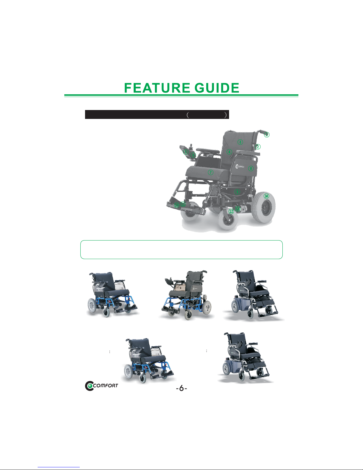
The Power Chair Front View LY-EB103
1.Handgrip
2.Foldable back switch
3.Seatback
4.Positioning belt
5.Battery charging inlet
6.Controller
7.Seat base
8.Flip-backward armrest
9.Battery
10.Foot plate
11.Heel loop
12.Caster wheel
13.Motor
14.Drive wheel
Every power chair has some different parts, the pictures only for
reference.
LY-EB103-N
LY-EB103-S
LY-EB103-A
LY-EB103-N
()
Optional light
LY-EB103-A
(Optional light)
Page 9

SPECIFICATIONS
Item No
Seat Width
Seat Depth
Seatback Height
Seat Base Height
Width
Height
Length
Motor Output
Battery
Batteries Weight
Charger
N.W.(w/o battery)
Brakes
Max loading
Slop Gradeability
Range
Front Wheels
Rear Wheels
Maximum Speed
LY-EB103 LY-EB103-N
LY-EB103-S
LY-EB103-A
A 18" J 16"
17"
A 24.5" J 22.5"
Electric-Magnetic Brakes
120kgs
34.5"
40"
450WX24VX2pcs
25kgs(36AH)/ 31kgs(50AH)
24VX5Amp
43kgs
36AHX12VX2pcs/
50AH X 12V X2pcs
18"
Max:20"
Max:21"
A 27" J 25" A 27" J 25"
35kgs 30kgs
200WX24VX2pcs
20AHX12VX2pcs
15kgs(7.5kgs X 2)
24VX2Amp
10
25km
200X50 PU castor
2.5"-6" pneumatic tyre
8.5km/h
12
30km(36AH)/ 40km(50AH)
200X50PU castor
4.10/3.50-5
pneumatic tyre
/4.00-5(optional)
12 1/2X2 1/4
pneumatic tyre
(or PU tyre)
35.5"
39.5"
37.5"
43"
17"
35"
8.0km/h 9.0km/h
Page 10

1
2
3
4
5
6
7
1.Battery Condition Meter
2.Maximum Speed/Profile Indicator
3.On/OffKey
4.Horn Key
5.Speed / Profile Decrease Key
6.Speed / Profile Increase Key
7.Joystick
VSI Controller
The battery condition meter is locked in front of the joystick. This is a
10-segment illuminated display that indicates that the VSI is powered
on and also gives the battery status, and the electrical system status.
Batteries charged; VSI and
electrical system OK.
charge batteries if possible; VSI and
electrical system OK.
Charge batteries as soon as
possible; VSI and electrical system OK.
Indicates a fault in the VSI or the electrical
system. Refer to "Trouble Codes."
The joystick was not in the neutral
position when the controller was turned on. If you get "ripple up and
down of lights", turn off the controller, allow the joystick to return to
the neutral position, then turn on the controller.
When the batteries approach a discharged state, the first red light will
begin to slowly flash, reminding you the batteries need to be charged
immediately.
Red, yellow, and green lights lit:
Red, and yellow lights lit:
Red lights only lit or slow flash:
Rapid flash of lights:
Ripple up and down of lights:
Battery Condition Meter
CONTROL PANEL AND OPERATION
Page 11

CONTROL PANEL AND OPERATION
There are two keys that control either the speed or the profile. This
depends on how your VSI was programmed. Press the speed / profile
increase key to increase the speed or change the profile. The speed /
profile setting is displayed on the maximum speed / profile indicator. If
your power chair was programmed with a drive profile, contact your
Comfort Specialist for more information.
The horn key activates the horn.
The VSI has a feature that enables you to lock your power chair to
prevent unauthorized use.
Speed / Profile Keys
Horn Key
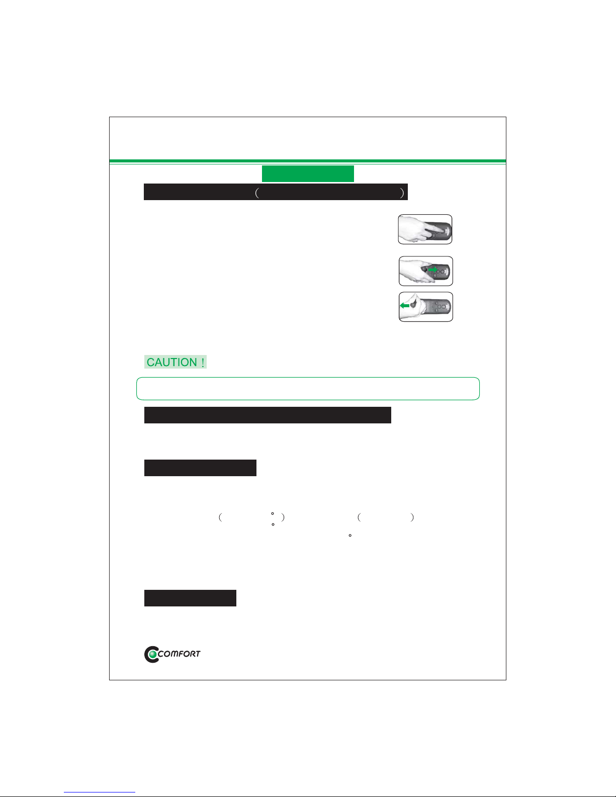
Locking / Unlocking the VSI
1.With the VSI powered on, press and hold
the on / off key. After 1second, the VSI
should beep.
2.Release the on / off key.
3.Push the joystick to the full forward
position until the VSI beep.
4.Pull the joystick to the full rearward
position until the VSI beep.
5.Release the joystick. There should be a
long beep.
6.The VSI is locked now.
To Lock the VSI Please follow the steps
We recommend that the first few times you operate your power chair,
you set speed to the slowest setting until you become familiar with your
new power chair.
VSI Controller
Page 12
1.Press the on / off key and power on the VSI. The
maximum speed / profile indicator should ripple
left and right.
2.Push the joystick to the full forward position until
the VSI beep.
3.Push the joystick to the full rearward position until
the VSI beep.
4.Release the joystick. There should be a long beep.
5.The VSI is unlocked now.
To Unlock the VSI Please follow the steps
If the above procedure fails to either lock or unlock the VSI, contact your
Comfort Specialist.
You charge the power chair batteries through the 3-pin socket located
on the front of the VSI. Off-board charger current should not exceed 12
amps. Contact your Comfort Specialist for more information.
The VSI controller is equipped with a thermal circuit. The circuit
monitors the temperature of the controller, which roughly translates to
motor temperature. In the event that the VSI controller becomes
excessively hot above 140 F motor current amperage is reduced.
For every degree above 140 F, the motor current limit is reduced by
.55 Amps until the VSI controller reaches 158 F, at which time the current
output is reduced to zero. This reduces your power chair's "power,"
which could also reduce your power chair's speed, and allows the
electrical components and motors to cool down. When the temperature
returns to a safe level, your power chair resumes its normal operation.
Off-board Charger / Programming Socket
Thermal Rollback
The VSI controller is designed with the user's safety as the prime
consideration. It incorporates many sophisticated self-test features
Trouble Codes
-10-
CONTROL PANEL AND OPERATION
VSI Controller
Page 13

which search for potential problems at a rate of 100 times per second. If
the VSI detects a problem either in its own circuits or in the power chair's
electrical system, it may decide to stop the power chair, depending on
the severity of the problem. The VSI is designed to maximize the user's
safety under all normal conditions. The table below identifies the
individual error codes. Error codes are displayed as a rapid flashing. If
you get one of these error codes, contact your Comfort Specialist.
Trouble Code
Diagnosis an Solution
The batteries need charging or there is a bad connection to
the batteries. Check the connections to the batteries. If the
connections are good, try charging the batteries.
The left motor has a bad connection. Check the left motor
connection.
The left motor has a short circuit to a battery connection.
Contact your Comfort Specialist.
The right motor has a bad connection. Check the right motor
connection.
The right motor has a short circuit to a battery connection.
Contact your Comfort Specialist.
The power chair is being inhibited by the battery charger.
Unplug the battery charger.
A joystick fault is indicated. Make sure that the joystick is in
the neutral center position before turning on the controller.
A controller fault is indicated. Make sure that all connections
are secure.
The parking brakes have a bad connection. Check the
parking brake and motor connections. Make sure the
controller system connections are secure.
An excessive voltage has been applied to the controller.
This is usually caused by a poor battery connection. Check
the battery connections.
1
2
3
4
5
6
7
8
9
10
CONTROL PANEL AND OPERATION
VSI or Vr2 Controller
Page 14

CONTROL PANEL AND OPERATION
1
2
3
4
5
6
7
8
9
Page 15

CONTROL PANEL AND OPERATION
Page 16

CONTROL PANEL AND OPERATION
Page 17

CONTROL PANEL AND OPERATION
-15-
Page 18

CONTROL PANEL AND OPERATION
-16-
Page 19

CONTROL PANEL AND OPERATION
-17-
Page 20

CONTROL PANEL AND OPERATION
-18-
Page 21

-19-
CONTROL PANEL AND OPERATION
Page 22

Flip-backward armrest
Push down the armrest switch, and pull theArmrest up.
You can flip-backward the armrest before you get on / off your power
chair.
Before you drive, restitute the armrest.
When driving, don't flip backward the armrest.
Foldable back
Push down the switch, and push the Backrest down.
Foldable back can save the space when you store up the power chair.
Before you drive, restitute the backrest.
-20-
Page 23

Push up the switch, and pull the footrest up.
Swing away detachable footrest
Before you drive, restitute the footrest.
Adjustment the controller
-21-
You may ask the service agent to adjust the controller's position to get a
more comfortable driving.
For LY-EB103-A
You may ask the service agent to adjust the footplate angle to get a more
comfortable position.
Page 24

DISASSEMBLY
1.Remove the
footrest.
2. Lift the seat.
3. Disassemble
the Velcro strap.
4.Push down the
back support.
5.Lift both
seatrest tubes.
6. Fold backrest.
-22-
7.Finish
You could take off the batteries when carrying.
If you forget the connections, check with CHARGE BATTERY.
(FOR LY-EB103-S, LY-EB103-A)
Page 25

VSI Controller
Left side of the motor
Free-wheel levers are
parallel to the wheels.
Free-wheel levers are
vertical to the wheels.
Normal Driving
Freewheel Mode
Right side of the motor
Do not use your power chair in freewheel mode without an attendant
present.
Avoid freewheel mode, when driving down a slope.
Do not attempt to personally place your power chair in freewheel
mode when sitting on the power chair.
Do not place your power chair in freewheel mode while on an incline.
-23-
Turn the clutch lever
clockwise to get the
free-wheel mode.
Turn the clutch lever
anti-clockwise to get
the free-wheel mode.
A-Series Controller
Page 26

Getting onto and off of your power chair requires a good sense of
balance. Please observe the following safety tips when getting onto and
off of your power chair.
Fully charge the batteries.
Push the manual freewheel level to the drive position.
Before Getting On Your Power chair
Operation
Pre-ride Adjustment And Checks
Position yourself as far as possible in the power chair seat to prevent
the power chair from tipping and causing injury.
Avoid using your armrests for weight bearing purposes. Such use may
cause the power chair to tip and cause personal injury.
Avoid putting all of your weight on the footrest. Such use may cause
the power chair to tip and cause personal injury.
Never attempt to get onto and off your power chair without first turn off
your power chair. Turning off your power chair prevents the power
chair from moving if accidental contact with the throttle control lever is
made.
Is your proposed path clear of people, pets, and obstacles?
Have you planned your route to avoid adverse terrain and as many
inclines as possible?
Are you positioned comfortably in the seat?
Is the seat locked securely in place?
Is the speed adjustment dial set to a slower setting?
Does your power chair horn work properly?
-24-
GETTING ONTO AND OFF OF YOUR POWER CHAIRGETTING ONTO AND OFF OF YOUR POWER CHAIR
Page 27

-25-
Page 28

-26-
Page 29

Item
Mcdel
Output Current
Output Voltage
Input Current
Input Voltage
Efficiency
Performance
Charging Method
Battery Application
Output Detection
Operating Temperature
Operating Humidity
Operating Height
Measurement
Weight
Color
Specification
HP1202B
2a dc+5%
24.0Vdc+2%
1.0A
95-250vac
Ac-dc min82%
Switching mode
Constant voltage, constant current
24v sealed lead acid batteries maximum
Capacity 55 AH
1.short circuit detection
2.output voltage/current limit
3.reverse power protected
0 ~40
20%~85%
0m~300m
L125mm w67mm l140mm
365g
Black
-27-
HP1202B 2A
LEAD-ACID BATTERY CHARGER INSTRUCTION
1. Specification
(1)Remove the battery from the original equipment.
(2)Make sute the power cord. Gattery cable. Battery terminals are in
Good condition
(3)Make sure the charge output voltage is the same as the connecting
Battery.
(4)Connect the plug of battery charge the socket of battery.
(5)Make sure the AC voltage is correct and plug in the power cord
Normally the LED(power)light will trun on when clcctric current
Passes.
(6)Charging start during charging LED(charge)will indicate orange
Light. When it truns to green light.that means well-charged.
2.Operating lnstruction
(2A CHARGER FOR LY-EB103-S )LY-EB103-A
Page 30

-28-
3.LED Indication
LED(power)-red light on:power on
LED(charge)-orange ligiht on:charging
green light on:full-charged
(1)led(power)light is off
If the fuse. Is broken. The fuse(fl)should be replaced by the
manufacturer or its service agent or a similar qualified person in
order to avoid a hazard.
Please have the battery charger to be recovered.
(2)led(charge)light is off
check to see the clips connection is correct.
If the battery is full charged, the led (charger)light will be off.
If light is still off, the battery may be defectivc.
(3)orange light can not turn to green
the battery can not be charged, please check and recover it.
(4)orange light trun to creen immediately
check to see the battery is fully charged. If the battery is not
fully charged. It may defective. Please have it to be recovcred.
4.lroubles shooting
For Indoor Use, Or Do Not Expose Top Rain.
Disconnect The Supply Before Making Or Breading The
connections To the Battery.
Warning:explosive Gases Prevent Clames And Sparks
provide adequate Ventilation During Charging.
The Maximum Rate Capacity Of The Sealed Acid Battery
you Can charge Is 55 Ah, Never Charge-non-rechargeable
batteries.
The Battery Must Be Placed InA Well Ventilated Area During
charging.
The Battery Charger Must Be Plugged In To An Earthed
socket-outlet.
To Prolong Charger Life, Do No Connecr The Short-output For
longtime.
Though Charger Charge Automatically And Can Be Used For
deeply discharged Battery, Do Not Use For Extremely Discharged,
short Aged and Defective Battery.
Use The Charger Only For 24 V Sealed Lead Acid Barreries.
(1)
(2)
(3)
(4)
(5)
(6)
(7)
(8)
(9)
5.caution
Page 31

The BATTERIES
1.We recommend deep-cycle batteries that are sealed and maintenance
free. Both sealed lead-acid and gel cell are deep-cycle batteries that
are similar in performance in your power chair. Do not use wet-cell
batteries, which have removable caps.
2.Following situations will combust more power, and the driving distance
will decrease.
Incline
Winter
Over-weight
3.Following rules will keep the batteries work longer.
Avoid charging after the batteries use out, charging after all day
power chair use on a daily basis.
Unplug the hub in 40 hours after the batteries fully charged.
Charge every three days to keep the batteries full after infrequent
or sporadic power chair use.
-29-
Do not remove the caps from sealed batteries. Water cannot be added
to sealed batteries.
Avoid using the batteries in an airless place.
The batteries acid could cause blindness or burning. If the batteries
acid contacts eyes, skin, clothes, or articles, rinse with water as soon
as possible. If battery acid is ingested, drink lots of water, and seek
medical assistance immediate.
Do not use other power chair's batteries to avoid damage to your
power chair.
When your power chair is being transported, make sure your power
chair and its batteries are secured.
The batteries would degenerate and the drive distance would
decrease after normal use for some time.
You can change the batteries if the drive distance becomes half after
charging full.
Change two batteries at the same time to optimize the best effect.
Page 32

CHANGE BATTERIES
1.Loosen the battery bind.
2.Disconnect the RED cables YELLOW cables BLACK cables.
3.Remove the old batteries and place new batteries.
4.Connect the RED cables YELLOW cables BLACK Cables.
1.Disconnect the plugs from the batteries.
2.Loosen the battery bind.
3.Remove the old batteries and place new batteries. (Put the grip
upward.
4.Connect the plugs.
Wrong connection would damage the batteries, and your power chair
would not turn on.
If your power chair's batteries become frozen, do not attempt to charge
them.
Cold or frozen batteries should be allowed to warm up for several days
prior to recharging.
If not sure how to change the batteries, contact your authorized Comfort
provider for assistance.
VSI Controller
A-Series Controller
BR
BR
Controller
Yellow
Yellow
Block
Block
Red
Red
-30-
Please Follow These StepsPlease Follow These Steps
Page 33

EMI/RFI
Laboratory tests performed by the Food and DrugAdministration FDA
have shown that radio waves can cause unintended motion of electric
power chairs. Radio waves are a form of electromagnetic energy EM .
When electromagnetic energy adversely affects the operation of an
electrical device, that adverse effect is called Electromagnetic
Interference EMI or Radio Frequency Interference RFI .
The following FAQs summarize what you should know about EMI/RFI.
Use this information to minimize the risk that EMI/RFI will adversely
affect your power chair.
Radio waves are emitted from the antennas of cellular phones, mobile
two-way radio such as walkie-talkies and CBs , radio stations, TV
stations, amateur radio HAM transmitters, wireless computer links,
microwave sources, and paging transmitters. Radio waves are a form
of EM. Because EM is more intense closer to transmitting antennas
sources of emission , the EM fields from two-way radios are of
special concern to electric power chair users.
EMI/RFI Warnings
EMI/RFI Frequently Asked Questions FAQS
Where do radio waves come from?
This is difficult to predict. The answer would depend on a number of
factors:
The strength of the radio waves.
The construction of your particular power chair.
The location of your power chair whether it is on level ground or on
an incline .
Whether or not your power chair is in motion.
The motion of any electric power chair affected by EMI/RFI can be
erratic. The power chair may come to a sudden stop or move in an
uncontrolled manner. Also, it is possible for EMI/RFI to release the
brakes of an electric power chair. Some intense EMI/RFI can even
damage the control system components of an electric power chair.
If EMI/RFI affects my power chair, what kind of motion should I expect?
-31-
Page 34

EMI/RFI
Unfortunately, EMI/RFI may be difficult to recognize, since the signals
from radio sources are invisible and may be intermittent. However, the
FDA recommends that you report all incidents of unintended motion or
unintended brake release of your electric power chair to the power
chair's manufacturer and, if possible, determine whether or not there
was a radio wave source nearby at the time of the incident.
One precaution you can take against inadvertent motion of your power
chair is to make certain that you or someone else is not the cause of the
unintended motion.
Turn off your power chair by removing the key from the key switch
when you are getting on or off your power chair.
Never leave the key in the key switch of an unattended power chair.
Each make and model of electric power chair differs in its ability to resist
EMI/RFI. That is, each power chair has a particular level of resistance to
EMI/RFI. This resistance is measured in volts per meter V/m . A
higher resistance level offers greater protection against EMI/RFI. In
other words, an electric power chair with a high resistance level is less
likely to be affected by a strong radio source than is an electric power
chair with a low resistance level.
The FDA has written to electric power chair manufacturer and requested
that those manufactures test their new models of power chairs to be
certain that they provide a reasonable degree of resistance against
EMI/RFI. The FDA has stated that all newly manufactured models of
electric power chairs should have a resistance level of at least 20 V/m.
This resistance level provides a reasonable degree of protection
against the common sources of EMI/RFI.
Is there any way to know for certain whether or not radio waves are the
cause of any unintended motion of my power chair?
Are all power chairs susceptible to EMI/ RFI ?
What is the FDA doing about the problem?
-32-
Page 35

EMI/RFI
Electric power chair manufacturers clearly label new products with
that product's resistance level or state that the resistance level is not
known.
The labeling or informational material supplied with new electric
power chairs must explain what the resistance level means and warn
users about the possibility of EMI/RFI and hope to avoid it.
Electric power chair manufacturers undertake an educational program
to inform electrical power chair users and their caregivers about the
problems associated with EMI/RFI and about the actions they can take
to minimize the risk of EMI/RFI.
While there is no exact way to tell if your power chair is totally safe, an
immunity level of 20 V/m is generally achievable and useful. This
product has been tested and passed at an immunity level of 20 V/m.
Adding accessories and components or modifying the unit may change
the susceptibility to EMI/RFI.
If you have had your power chair for some time and have not experiences
any unintended motion, it is not likely that you will have a problem in the
future. However, it is always possible that EMI problems could arise if
you are close to a source of radio waves. Therefore, it is very important
for you to be alert to this possibility.
Here are some precautions you can take:
Do not turn on or use hand-held personal communications devices,
such as citizen's band CB radios an cellular phones, while your
power chair is turned on.
Be aware of nearby radio wave transmitters, such as radio or TV
stations and hand-held or mobile two-way radios. Try not to operate
your power chair too close to those transmitters. For example, if you
are on an electric power chair with a resistance level of at least 20V/m,
you should remain at least three feet from a hand-held two-way radio
and at least ten feet from a mobile two-way radio.
Be aware that adding accessories and/ or components, or modifying
your power chair in any way, may change its EMI/RFI resistance level
and may make it more susceptible to interference from radio wave
sources.
The FDA has also requested or recommended that :
What can I do to find out if my power chair is likely to be affected by
EMI/RFI?
What can I do to reduce the risk of my power chair being affected by
EMI/RFI?
-33-
Page 36

What should I do if my power chair moves unexpectedly?
If unintended motion or unintended brake release occurs, turn off your
power chair by removing key as soon as it is safe to do so.
EMI/RFI
-34-
Page 37

MAINTENANCE
Please charge after prolong driving.
Keep your power chair in a dry place or put a waterproof over it to
prevent moisture ingress when it is not being used.
Please wipe your power chair with dry clean cloth as often as possible.
Using water may damage the electronic assembly.
Avoid using benzene, gasoline..., these would deface your power
chair.
Please check all the connectors to prevent from disconnecting.
Check if all screws of controller, batteries and differential have been
tightly screwed.
Charge at least every three months to maintain high efficiency of
battery.
Check front/rear wheel bearing if there is abnormal sound in axles.
Please get your annual maintenance by the authorized Comfort
provider.
Daily Care
Monthly Maintenance
Half year Maintenance
Annual Maintenance
-35-
Page 38

This warranty is extended only to the original purchaser/user of our
products. Your original sale receipt will be necessary as proof of
purchase before any warranty service is rendered.
COMFORT warrants products sold thru authorized dealer/distributor
only.
COMFORT warrants your products to be free from defects in material
and workmanship under normal use for the following time periods.
PLEASE COMPLETE FILLED OUT AND RETURN YOUR COMFORT
WARRANTY REGISTRATION CARD WITHIN 30 DAYS OF YOUR
PURCHASE.
WARRANTY
Warranty Exclusions
ABS plastic shrouds and footrest covers (wear items and not
warranted)
Batteries (the battery manufacturer provides a six-month limited
warranty)
Tires and tire tubes (wear items and not warranted)
Upholstery and seating (wear items and not warranted)
Labor, service calls, shipping, and other charges incurred for repair of
the product
If the original purchaser/user finds a defective frame, and or a specific
part, and believe it is due to manufacture defect, that component will be
repaired or replace, at COMFORT's option and discretion. This warranty
does not cover any labor charges including, but not limited to, charges
incurred for installation of replacement parts or additional fees may be
imposed by the dealer or service agent. All transportation costs and
shipping damage incurred while submitting parts for repair or replacement are the responsibility of the original purchaser.
For warranty service, please contact your authorized dealer/distributor
from whom you purchased your Comfort product.
Main Frame: 3 years
Drive train 1 year including controller, transaxle, motor, brake
Charger: 1 year
-36-
Controller, motor, charger, transaxle(gear box) warranty void if disassembly or modify.
Page 39

WARRANTY
The forgoing warranty shall not apply to purchase Comfort products
from unauthorized dealer/distributor, improper operation, serial number
has been removed or defaced, modification through the use of
unauthorized parts or attachments, accidental damage, or problem
cause by neglect or misuse, damage repairs made to any components/
parts without consent of COMFORT, or products damage by
circumstance beyond COMFORT's control, and such evaluation will
solely determined by COMFORT. The warranty shall not apply to
problems arise from normal wear and tear or failure to adhere the
instructions.
implied warranties. COMFORT shall not be liable for any consequential
or incidental damages whatsoever.
The forgoing warranty shall not be applied to the following:
1.If it is not inspected regularly according to the stipulations of Comfort.
2.If it is incorrectly maintained.
3.If the power chair is not operated according to user's manual or
exceeding the limitation or capacity stated in the user's manual (with
respect to rider or weight).
4.If extra components or accessories are used or carried in conjunction.
5.If the power chair is driven in inhospitable places or under
extraordinary conditions.
6.If the power chair is modified without Comfort's permission.
7.If it is affected by smoke, medical / chemical substances, bird
droppings, salt, acid rain, flying rock and metal particles, and other
external factors etc.
8.If it is affected by causes such as typhoon, flood, fire, earthquake, and
other natural disasters etc.
The forgoing warranty is exclusive and in lieu of other express and
Limitatations And Exclusions
-37-
Page 40

BASIC TROUBLESHOOTING
Check if the fuse has blown. Check that the clutch switch lever is in
correct position.
Check all electrical connections.
Check the battery condition meter.
Your power chair will stop to protect the batteries when the voltage is
under 17V.
When batteries are charging, your power chair can not work.
Driving up a very long steep may cause abrupt stop. This is as a result
of the circuit breaker trip. When the breaker trips, the main circuit
breaker reset button pops out. Please wait about 2 minutes, and push
in the reset button to reset the breaker.
The limpid plastic on the battery is circuit breaker. VSI has one circuit
breaker, and SHARK has two circuit breakers.
When Your Power chair Can't Turn On Or Stop Suddenly
When Driving
If the breaker trips frequently, you may need to charge your batteries
more often. You may also need to have your authorized Comfort provider
perform a load test on your power chair's batteries.
If a surface is bumpy or uneven, check that the batteries and other
connections are secure.
If your power chair cannot work after your check, contact your
authorized Comfort provider for assistance.
-38-
Page 41

0606500
 Loading...