

Page 1
USER GUIDE
& MANUAL
COMFORTCOMPANY.COM
BODILINK™ HEAD SUPPORT
UM-BODILINK-HEAD-SUPPORT REV0817
Page 2

Thank you for choosing COMFORT COMPANY
ABOUT US CONTENTS
®
At Comfort Company we are dedicated to creating and
manufacturing seating and postural support systems
designed for people with a wide range of rehabilitation
needs. Whether for pediatric, geriatric, or bariatric needs
we are committed to providing our customers with quality products designed for comfort, durability, and ease of
use. Our vision is to lead in the development, manufacturing, and delivery of the most innovative seating and
positioning products which provide the highest level of
comfort, functionality, and quality of life for the user.
CONTACT INFORMATION
1.800.564.9248
406.522.8563
customerservice@comfortcompany.com
www.comfortcompany.com
Customer Service
Bozeman, Montana
Manufacturing
New Berlin, Wisconsin
BEFORE USE
SAFETY GUIDELINES
Symbols 3
General Safety 3-4
Intended Use/User 4
Parts Detail 5
INSTALLATION & SET UP
Attachment To Back Supports 6-11
Acta-Back® Series, Acta-Embrace
Acta-Relief™ Head Support Bracket 7
Acta-Relief™ with Compass® 4 7
Acta-Relief™ with Compass® Power Mount 8
Using Radius & Posterior Mounting Plates 9
Mounting to Permobil® with Uni-Track 10
Mounting to Quantum® with TRU-Comfort
Adding a Link to the Hardware 12-13
Connecting Hardware and Support Pads 14
Adjustments 15-16
Finishing Installation 17
CLEANING AND MAINTENANCE
Cleaning 18
Inspection 19
Reuse 19
Storage 19
Disposal 19
WARRANTY AND REPLACEMENT
Lifetime Guarantee 19
Replacement Procedure 19
COMMENTS
®
(any hardware) 6
2
11
15
Back
Cover
The appropriate Comfort Company positioning product
is intended to improve every day user function and comfort while providing support and stability for a variety of
rehabilitation needs. However, prior to using any Comfort
Company support, it is important that each individual be
assessed by a qualied healthcare professional for but not
limited to, mobility, nutrition, current condition, goals, and
health history. In addition to this initial assessment, individuals should be regularly monitored by a health care professional for any changes in their condition.
This user guide and manual is for reference purposes only
and is not intended to substitute for advice given by a physician or other licensed healthcare professional. You should
not use this information for self-diagnosis or self-treatment
of a health problem or condition. Contact your healthcare
provider immediately if you suspect that your health problem or condition has changed or worsened.
Before using, make sure that you are properly trained to
operate the equipment for its application. Failure to do so
could lead to discomfort, injury or damages.
NOTE: “We,” “Us” and “Our” refers to Comfort Company. “You” refers to the product purchaser or user.
2
INTRODUCTION www.comfortcompany.com
Page 3
SAFETY GUIDELINES
SAFETY SYMBOLS
Warning!
Prohibited!
GENERAL SAFETY
No Smoking
Do Not Expose to sources of excessive heat such as open ame or spark.
Do Not Cut
or Puncture
Without following the specied procedure, this indicates potentially
hazardous conditions that could lead to personal injury, inadequate
performance, product damage or malfunction.
Indicates actions that should NOT be performed at any time under any
circumstance. These actions could result in personal injury and/or damage
to the product or equipment being used.
Although this product meets ammability requirements, we do not
recommend smoking while using this product. Damage from smoke and
ame is not covered by the lifetime warranty. You must consider additional
safety precautions when choosing to smoke while using this product.
Avoid sharp objects. Do not modify the product. Doing so will void its
warranty and may lead to personal injury or alter the effectiveness of the
product by increasing the risk factors for skin breakdown and/or instability.
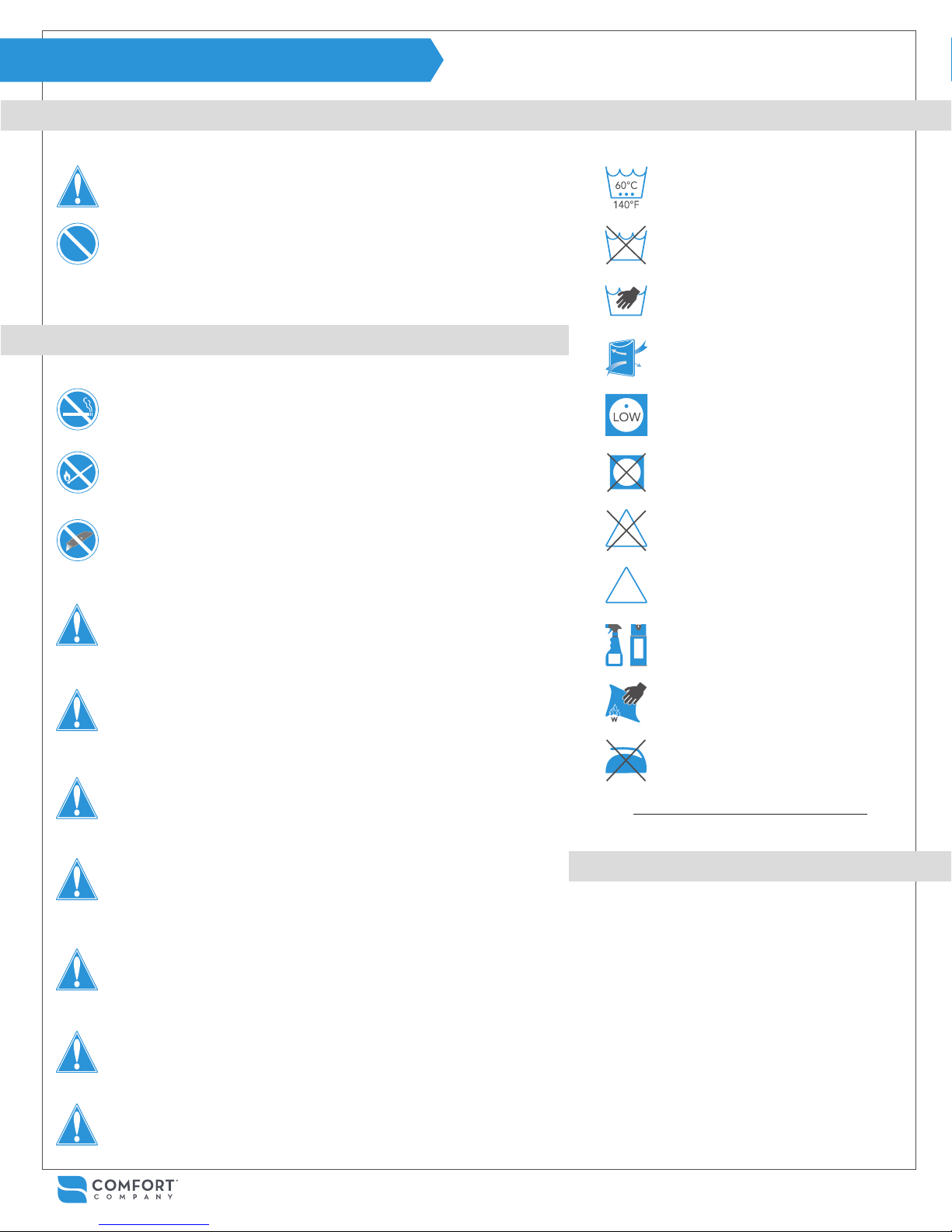
CARE SYMBOLS
Wash Cover Only Warm Cycle (Maximum Temperature)
Do Not Wash
Hand Wash
Air Dry Only
Hang to Dry
Tumble Dry Low
Do Not Tumble Dry, Steam Clean or
Autoclave
Do Not Bleach
You must READ and FOLLOW all instructions, notes and warnings included in this
manual. Understanding how to care for your product is the key to safe and proper
use. Share this information with all caretakers to help them meet your healthcare
needs and ensure your safety.
Comfort Company cannot be held responsible for damages or injury due to misuse
of the product or failure to follow instructions provided in this manual. Please contact
us if you require further assistance in understanding cautions, warnings or instructions
for using or maintaining your product.
Installing alternate parts to your wheelchair may change the intended structure and
function of the equipment. Be sure to assess the need for additional safety features
for your chair such as anti-tip bars or other available options in order to maintain
stability during use. Use this manual in conjunction with the user manual that came
with your chair to ensure safety guidelines are being met.
Check packaging and inspect all parts for damage before use. DO NOT USE if damaged and contact Comfort Company immediately for further instruction. Check regularly for loose components and tighten as necessary. Contact Comfort Company if
wear or damage is noted.
During the rst few hours of use, a healthcare professional should be available to
observe skin condition and assess the likelihood of skin breakdown.
During regular use, periodically check for skin discoloration and/or irritation. If discoloration should occur and not disappear after 30 minutes of non-use, discontinue use
and consult with your healthcare provider immediately.
Bleach Okay
Antibacterial or Disinfectant Spray
Wipe with Water Only
Do Not Iron
Detailed cleaning instructions on page 18
PLEASE NOTE
The information in this manual was gathered and recorded with
the latest specications available at the time of publication. Due
to our continued effort to reassess and improve our products,
information found in this manual such as drawings and notes may
vary slightly from the product that you purchased. We reserve the
right to make changes to products as they are deemed necessary. To check for the latest version of this manual please visit us
at www.comfortcompany.com.
DO NOT place anything in between the user and the product. Additional materials
may reduce the effectiveness of the product and increase risk factors for skin breakdown and instability.
Always use the cover and base with any inserts as a complete assembly. Never use a
cover other than one intended for your specic product and size.
The directions provided will help to maintain and extend the
life of your product and ensure it is covered by the Comfort
Company Lifetime Guarantee. Please see complete warranty
information on page 19.
SAFETY GUIDELINES
3
Page 4

SAFETY GUIDELINES
BODILINK™ HEAD SUPPORT SAFETY DETAILS
PROHIBITED! Never use the equipment to maneuver a
chair or anything that it is attached to. It is never to be
used as a handle, lift, guide or support for anything other
than what it was intended. (ex. support during transfers.)
PROHIBITED! Never use the equipment unless all components are fully functional. Any issues should be addressed
by contacting your dealer or customer service. Do not at-
tempt to make your own modications or repairs.
This product is designed for the intended user and use
only. Be aware that any modications could potentially
endanger the user, cause discomfort or damage.
This product passed crash testing. However, when
possible, do not use head support during transport.
Repeated or excessive force (braking or crash) could
potentially change adjustment or cause extra wear
shortening the life of the product. Use after a crash is
not recommended.
Caregivers: It is necessary to learn from a healthcare provider
how to properly adjust the equipment for the user’s specic
positioning needs and goals.
WARNING! Ensure that the product does not interfere with
any other chair components. Interference could jeopardize
effectiveness and user safety as well as cause damage.
WARNING! It is necessary to fully articulate power recline
features to ensure there is no possible equipment interference after installation. Do so slowly while watching closely.
ATTENTION! Make sure that the head support is securely
mounted to the back support system and it is adjusted
properly each time it is in use.
ATTENTION! Always check that the gear teeth in each joint
are aligned for full tooth engagement before nal tighten-
ing. Failing to do so could cause wear on the teeth leading
to parts slipping out of adjustment or hardware failure.
ATTENTION! Unless otherwise specied, fasteners
should be tightened to 10.5 Nm (93 lb-in).
CAUTION! Please consider that adding additional
links to the hardware may reduce the overall strength.
INTENDED USE - MATERIALS
COMFORT-TEK™ fabric cover is uid-resistant, easily cleaned at any time
and soft to the touch. Comfort-Tek™ fabric has stretch which helps alleviate
pressure and conforms to both support pad and user.
STRETCH-AIR™ fabric cover is 2-Ply designed to be breathable on the
surface for comfort while the bottom layer is uid-resistant for cleanliness.
The multi-directional stretch allows for optimal conforming to the user and
support pad shape.
GLIDEWEAR® fabric cover is intended for maximum hair and skin protection by reducing shear. Recommended most for those with abnormal tone
causing involuntary movements, difcult postures and frequent repositioning
All fabrics used in BodiLink™ Head Support covers are latex-free.
Comfort-Tek™ fabric is used on all head support pad covers along
the outer edge.
BodiLink™ Head Support pads come in 2 levels of rmness (soft and
extra soft). Both use a layer of Viscool® extra soft foam over a high
resiliency foam base layer. This combination allows for immersion and
conforming to the user for optimal surface contact, comfort and pressure redistribution.
INTENDED USER
BodiLink™ head support is intended for those with positioning and support needs as deemed necessary by a qualied healthcare professional.
BodiLink™ head support offers a wide variety of available positions to accommodate user rehabilitation needs and goals while allowing for function and
comfort. The sizes available and range of adjustability t pediatric to full grown users and should be matched by the healthcare provider to suit the user
needs. Adjustments or replacement components may be necessary as changes in condition occur or to accommodate developments such as growth.
4
SAFETY GUIDELINES - INSTALLATION & USE www.comfortcompany.com
Page 5
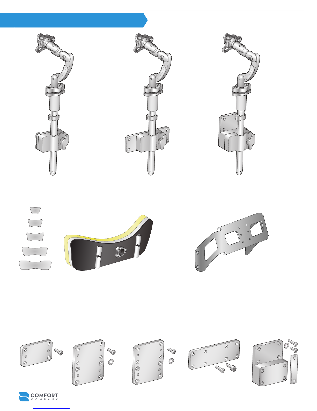
PARTS DETAIL
BODILINK™ HEAD SUPPORT
REMOVABLE HARDWARE
(BL-HSH-FX)
BODILINK™ HEAD SUPPORT PAD
6” W X 3.5” L (BL-HSP1-6W3L) (BL-HSP2-6W3L)
8” W X 4” L (BL-HSP1-8W4L) (BL-HSP2-8W4L)
10” W X 5” L with adjustable wings (BL-HSP1-10W5L) (BL-HSP2-10W5L)
14” W X 5” L with adjustable wings (BL-HSP1-14W5L) (BL-HSP2-14W5L)
18” W X 5” L with adjustable wings (BL-HSP1-18W5L) (BL-HSP2-18W5L)
BODILINK™ HEAD SUPPORT
REMOVABLE HARDWARE FOR
QUANTUM® (BL-HSH-FX-PW1)
*14WX5L size without cover shown
Soft Extra Soft
ADDITIONAL BODILINK™ HEAD SUPPORT HARDWARE
EXTRA SPACER PLATE
(BL-HSH-SPCR)
RADIUS MOUNTING PLATE
(BL-HSH-SPCR-RAD)
POSTERIOR MOUNTING PLATE
(BL-HSH-SPCR-POST1)
BODILINK™ HEAD SUPPORT
REMOVABLE HARDWARE FOR
PERMOBIL® (BL-HSH-FX-PW2)
ACTA-RELIEF™ HEAD SUPPORT BRACKET
For 14”W Back Supports (HSH-AR14W)
For 16”W Back Supports (HSH-AR16W)
For 18”W Back Supports (HSH-AR18W)
For 20”W Back Supports (HSH-AR20W)
QUANTUM MOUNTING PLATE
(BL-HSH-SPCR-POST2)
PERMOBIL MOUNTING PLATE
(BL-HSH-SPCR-TRCK1)
INSTALLATION & USE
5
Page 6

INSTALLATION (STANDARD)
For Acta-Back®, Acta-Back® Deep, Acta-Back® Contour,
Acta-Back® LTS, Acta-Embrace®, Acta-Embrace® LTS,
& Visco Back®. All tools needed are provided.
Note: Head support pad is not shown but in most
cases will come attached to hardware. See page
14 for instructions on attaching head support pad.
Instructions for adding a link on pages 12-13.
Start by turning knob A counterclockwise.
1
Remove hardware shaft C from mounting bracket B and set
2
aside.
Loosen bolts D with ⅛” allen wrench and remove along with
3
washers E and spacer plate F from mounting bracket B.
Remove back support cover (not pictured) allowing access
4
from both sides to head support holes on back support shell G.
Align mounting bracket B and spacer plate F with head sup-
5
port holes on the back support shell. When using Compass®
Power Mount Hardware, do not use spacer plate F so either
discard or retain for future use.
Attach B and F with bolts D and washers E from the front face
6
of the back support shell G and tighten to 65 lb-in.
Replace and secure back support cover.
7
Insert hardware shaft C into mounting bracket B and turn knob
8
A clockwise to secure. Note: Make sure at least ½” of shaft C
is completely through the bottom of B at all times (see page 7,
gure 2.5). See pages 15-17 for nal adjustments.
Figure 2.1
D
6
Figure 2.2
5
G
C
E
B
A
3
2
F
6
INSTALLATION & USE www.comfortcompany.com
1
Rear view of Acta-Back® support shell shown
Page 7

INSTALLATION (ACTA-RELIEF™)
For Acta-Relief™ & Acta-Relief™ LTS using Compass® 4
Mounting Hardware. All tools needed are provided.
If Acta-Relief™ Head Support Bracket is not already
attached, please follow the below prior to step 1.
G
Figure 2.3
J
K
L
Align 4 holes on back support shell G with head
support bracket H as shown in Figure 2.3 and
attach with fasteners and allen wrench provided.
Assembly order:
H - G - at washer J - safety washer K - screw L
Note: Please refer to Page 6, Figure 2.1 for steps 1 - 3.
Start by turning knob A counterclockwise.
1
Remove hardware shaft C from mounting
2
bracket B and set aside.
Loosen bolts D with ⅛” allen wrench provided
3
and remove along with washers E and spacer
plate F from mounting bracket B.
Align mounting bracket B and spacer plate F
4
(if desired) with desired head support holes on
head support bracket H. (Figure 2.4)
H
B,F
Figure 2.4
H
4
5
Attach B and F with bolts D and washers E
5
from the inner face of the head support bracket H and tighten to 65 lb-in.
Insert hardware shaft C into mounting bracket
6
B and turn knob A clockwise to secure. Note:
Make sure at least ½” of shaft C is completely through the bottom of B at all times (see
gure 2.5). See pages 15-17 for nal adjustments.
Note: Head support pad is not shown
but in most cases will come attached to
hardware. See page 14 for instructions on
attaching head support pad. Instructions
for adding a link on pages 12-13.
C
½”
min.
Figure 2.5
6
A
INSTALLATION & USE
7
Page 8

INSTALLATION (ACTA-RELIEF™ POWER)
For Acta-Relief™ & Acta-Relief™ LTS using Compass®
Power Mount Hardware. All tools needed are provided.
Note: Head support pad is not shown but in most
cases will come attached to hardware. See page
14 for instructions on attaching head support pad.
Instructions for adding a link on pages 12-13.
Start by turning knob A counterclockwise.
1
Remove hardware shaft C from mounting bracket B and set
2
aside.
Loosen bolts D with ⅛” allen wrench and remove along with
3
washers E and spacer plate F from mounting bracket B. Do
not use spacer plate F with Acta-Relief™ with Compass®
Power Mount so either discard or retain for future use.
Align mounting bracket B with desired head support holes
4
on power mount bracket G. Note: If needed, partially remove
back support cover (not pictured) allowing additional access
to head support holes on mounting bracket G from the front.
Attach B with bolts D, washers E, and additional thick wash-
5
ers H provided from the inner face of power mount bracket
G and tighten to 65 lb-in. Replace and secure back support
cover if it was removed.
Insert hardware shaft C into mounting bracket B and turn
6
knob A clockwise to secure. Note: Make sure at least ½” of
shaft C is completely through the bottom of B at all times (see
page 7, gure 2.5). See pages 15-17 for nal adjustments.
Figure 2.6
D
C
Figure 2.7
5
E
D
E
H
4
G
B
A
3
2
F
8
INSTALLATION & USE www.comfortcompany.com
1
Page 9

INSTALLATION (RADIUS & POSTERIOR MOUNTING)
For Radius Back® or other Posterior Mount Back Supports using Radius Mounting
Plate BL-HSH-SPCR-RAD or Posterior Mounting Plate BL-HSH-SPCR-POST1.
All tools needed are provided.
Note: Please refer to Page 8, Figure 2.6 for steps 1 - 3.
Steps 3 - 4 may be complete already depending on how BodiLink™ Head Support was ordered in conjunction with Radius Back®.
Start by turning knob A counterclockwise.
1
Remove hardware shaft C from mounting bracket B and set aside.
2
Loosen bolts D with ⅛” allen wrench provided and remove along with washers E and spacer plate F from
3
We can only guarantee that BodiLink® Head Support system
will properly mount to the Comfort Company products listed
in this manual. Modications made in attempt to interface with
any other products voids warranty.
mounting bracket B. Parts D, E and F will be replaced so either discard or retain for future use.
Align mounting bracket B and countersunk holes of alternate spacer plate J and attach with provided at
4
head screws K. Make sure the screw heads are ush with spacer plate J when nished.
Now attach J to back support with button head bolts L and safety washers M and tighten to 125 lb-in using
5
” allen wrench. L, M and allen wrench provided with alternate spacer plate.
Insert hardware shaft C into mounting bracket B and turn knob A clockwise to secure.
6
Note: Make sure at least ½” of shaft C is completely through the bottom of B at all times (see page 7,gure
2.5). See pages 15-17 for nal adjustments.
Figure 2.8
K
J
B
4
Radius Back® without cover shown
Figure 2.9
5
Note: Radius Back® requires creating holes in the back support
cover at the T-nut locations for attaching mounting hardware.
M
L
INSTALLATION & USE
9
Page 10

INSTALLATION (PERMOBIL MOUNTING)
For Permobil® Back Supports with Uni-Track System
using Permobil Mounting Plate BL-HSH-SPCR-TRCK1.
All tools needed are provided.
We can only guarantee that BodiLink® Head Support system will
properly mount to the Comfort Company products listed in this
manual. Modications made in attempt to interface with any other
products voids warranty.
Start by turning knob A counterclockwise.
1
Remove hardware shaft C from mounting bracket B and set
2
aside.
Loosen bolts D with ⅛” allen wrench provided and remove
3
along with washers E and spacer plate F from mounting bracket B. D, E and F will be replaced so either discard or retain for
future use.
Align mounting bracket B and countersunk holes of alternate
4
mounting plate H and attach with provided at head screws
J and tighten. Fasteners and allen wrench are provided with
alternate mounting plate.
Loosely attach button head bolts K and safety washers L to
5
double nuts M through alternate plate H.
Slide nuts M into Uni-Track System slots to desired position
6
and fully tighten bolts K with 4mm allen wrench to secure.
Insert hardware shaft C into mounting bracket B and turn knob
7
A clockwise to secure. Note: Make sure at least ½” of shaft C
is completely through the bottom of B at all times (see page 7,
gure 2.5). See pages 15-17 for nal adjustments.
Figure 2.10
D
C
Figure 2.11
H
B
J
4
M
E
Figure 2.12
B
6
3
2
A
5
F
10
INSTALLATION & USE www.comfortcompany.com
L
K
1
Page 11

INSTALLATION (QUANTUM MOUNTING)
For Quantum® Rehab TRU-Comfort2 Back Supports on
TRU-Balance3 Seating System using Quantum Mounting Plate
BL-HSH-SPCR-POST2.
Note: Please refer to Page 10, Figure 2.10 for steps 1 - 3.
Steps 3 - 4 may be complete already depending on how BodiLink® Head Support was ordered. If so, skip to step 5.
Start by turning knob A counterclockwise.
1
Remove hardware shaft C from mounting bracket B and set aside.
2
Loosen bolts D with ⅛” allen wrench provided and remove along with washers E and spacer plate F from mounting
3
bracket B. Parts D, E and F will be replaced so either discard or retain for future use.
Align mounting bracket B and countersunk holes of mounting plate J and attach with provided at head screws K
4
using phillips head screwdriver. Make sure the screw heads are ush with mounting plate J when nished.
Attach J to back support with socket head bolts L and tighten using 4mm allen wrench. L provided with alternate
5
mounting plate.
Insert hardware shaft C into mounting bracket B and turn knob A clockwise to secure.
6
Note: Make sure at least ½” of shaft C is completely through the bottom of B at all times (refer to page 7, gure
2.5). See pages 15-17 for nal adjustments.
Figure 2.13
K
J
B
Figure 2.14
4
5
J
L
INSTALLATION & USE
11
Page 12

INSTALLATION (ADDING A LINK)
BodiLink® Head Support Hardware Kit will include an extra link
and fasteners to use if needed to reach extreme positions.
Remove bolt N and safety washer O from curved link P and top of hardware shaft C.
1
Remove hardware shaft C from mounting bracket B by turning knob A counterclockwise.
2
Turn hardware shaft C 180° so the visible gear teeth are facing the opposite direction.
3
Insert hardware shaft C into mounting bracket B and turn knob A clockwise to secure.
4
CAUTION! Please consider that adding additional
links to the hardware may reduce the overall strength.
Note: Make sure at least ½” of shaft C is completely through the bottom of B at all times (refer to page 7, gure 2.5).
Figure 2.15 Figure 2.16
P
O
N
3
1
C
C
A
B
42
Note: Head support pad is not shown but in most
cases will come attached to hardware. See page
14 for instructions on attaching head support pad.
12
INSTALLATION & USE www.comfortcompany.com
Page 13

INSTALLATION (ADDING A LINK)
Comfort Company cannot be held responsible for damages or injury due to misuse of the product or failure to follow instructions provided in the manual. Please contact
us if you require further assistance in understanding cautions, warnings or instructions for using or maintaining your product. Customer Support 1.800.564.9248
5
Align extra link R with gear teeth on hardware shaft C in the orientation shown below and fasten with
safety washer S and bolt T.
6
Align the other end of extra link R with curved link P and fasten with safety washer O and bolt N.
7
See pages 15-17 for information on nal adjustments.
Proper gear tooth alignment and engagement is essential for a secure set up
Figure 2.17
R
6
S
T
P
O
N
6
C
5
5
Figure 2.18
Gear Teeth Alignment
INSTALLATION & USE
13
Page 14

INSTALLATION (SUPPORT PAD)
In most cases, head support pad will come preassembled
with mounting hardware. All tools needed are provided.
Align ball link A and ring B with ball receiver C.
1
Loosely engage bolts D and safety washers E with ball receiver C to complete the assembly.
2
Continue to pages 15-17 for nal adjustments.
3
Figure 2.19
8W x 4L support pad shown
C
B
A
1
E
2
D
14
INSTALLATION & USE www.comfortcompany.com
Page 15

SET UP & ADJUSTMENTS
BodiLink™ Head Support hardware has 6 points of adjustment for height, angle, rotation and depth. All BodiLink™ Head Support pads have a
preformed curvature for optimal posterior contact, but the 3 largest head support pads have 2 points of adjustment for additional lateral support.
1A- 45º
*
7
1B- 80º
1C- 360º
2- 240º
3- 240º
4- 240º
Figure 3.1
5- 360º
6- 4.5”
Adjustment Point Ranges
2
A
1
14W x 5L pad shown
7*- +90º/-10º each
*14W5L, 10W5L, 18W5L Support Pads Only
Figure 3.2 Figure 3.3
B
1
C
1
3
5
4
6
SET UP & ADJUSTMENTS
15
Page 16

SET UP & ADJUSTMENTS
Use the 4mm allen wrench provided for all adjustment bolts.
Loosen all adjustment point bolts 1-5 allowing
1
for full articulation of the head support to a
desired position.
Note: BodiLink™ head support pads are designed to
be used in any orientation including ipped 180º as
shown in figure 3.4 to better address the user’s needs.
Assess and alter height adjustment 6 using
2
knob A if needed. Remember to leave at least
½” of hardware shaft C showing through the
bottom of the mounting bracket B.
While holding the head support pad in place,
3
loosely tighten adjustment points1-5.
Once all hardware links are lightly set, go back
4
and tighten all bolts evenly.
ATTENTION: It is crucial that adjustment
point 1 is tightened evenly all around to
prevent unwanted movement and the
gear teeth on points 2-5 must be properly
aligned and engaged for a secure set up.
To access wing adjustment 7 channels on
5
10”/14”/18”W head support pads, partially unzip the locking zippers under the
cover aps. Ensure gear teeth are properly
aligned before nal tightening.
Figure 3.4
14W x 5L pad without cover shown
7
Figure 3.5
1
4
1
7
2
3
16
5
Figure 3.6
Gear Teeth Alignment
B
6
A
C
SET UP & ADJUSTMENTS www.comfortcompany.com
Page 17

FINISH
Only locking feature set screws require the smaller allen
wrenches provided.
Finish by positioning collar D on hardware shaft C at the top of mounting bracket B.
6
Locate set screw E in the collar and tighten with 2mm allen wrench until contact is made with the
7
hardware shaft. This allows for easy positioning of the hardware if it is removed and then replaced.
Note: Collar D is retained in a track in the shaft. If the collar needs to be removed, remove the set screw F
located in the track at the bottom of the shaft with the 1.5mm allen wrench provided.
14W x 5L pad without cover shown
Figure 3.7
E
7
C
D
6
B
F
SET UP & ADJUSTMENTS
17
Page 18

CLEANING
Frequent heat drying and bleaching naturally cause fabric break down.
Air drying and cleaning without bleach are recommended whenever possible to help extend the life of the cover.
SURFACE CLEANING COMFORT-TEK FABRIC ONLY*
Spray with common household or commercial antibacterial
cleansers or disinfectants.
Wipe with damp, water-only cloth after disinfecting and let dry before use.
COMPLETE CLEANING (ALL FABRICS)
Machine wash cover using any common laundry detergents. Let dry completely before use.
Machine Wash any temperature
Maximum 66°C/150°F
Tumble Dry Low Temperature Only
Do Not Steam Clean or Autoclave
Do Not Tumble Dry High Temperature
Do not wash or dry Stretch-Air™ and GlideWear® covers along with hook and loop fasteners or other materials that could snag the fabric.
Note: Doing so could pull at the fabrics causing changes in the appearance but not the effectiveness of the fabrics.
Unzip cover and remove from head support pad and hardware.
Hand Wash when possible
Air Dry when possible
Do Not Iron
DISINFECTING (ALL FABRICS)
Unzip cover and remove from head support pad and hardware. Wash cover with water and bleach followed by thorough rinse.
Follow directions on bleach container. Let dry completely before use.
Machine Wash Maximum 66°C/150°F
Soiled foams should be replaced. Remove cover, dab foam with water-only cloth and let dry completely before replacing cover.
DO NOT submerge foam in any liquid, including water.
DO NOT use contaminated foam with multiple users.
Foam should not be exposed to light for any extended period of time. Light will cause discoloration of the foam. This only effects the
appearance of the foam, not the functional features. There is no need to attempt to “clean” discoloration caused by light exposure.
18
CLEANING & MAINTENANCE www.comfortcompany.com
Bleach
FOAM
Dab with clean, damp, water-only cloth.
Air Dry Only.
Page 19

MAINTENANCE
WARRANTY
INSPECTION
Inspect all head support components monthly.
Check and tighten all fasteners and adjustment points.
Inspect all materials for wear such as stretching, fraying,
fractures, and bends. Some wear with regular use is expected. Signs of excessive wear to any component should be
addressed by contacting your dealer or customer service
for repair or replacement parts.
REUSE
You must re-t the support to the new user or after extended
periods of non-use by the same user. Follow the "Set up &
Adjustments" procedure on Pages 15-17 to do so.
Before transferring to a new user, the product must be completely cleaned and disinfected as outlined on page 18.
This product is covered by the Comfort Company Lifetime Guarantee.
If a manufacturing defect should occur, the product will be replaced at
no cost to the buyer. Register your product at www.comfortcompany.
com/registration to activate Lifetime Guarantee.
If manufacturing defects should occur, discontinue use immediately.
Wear from regular use is not considered a manufacturing defect. Replacement parts are available by contacting Customer Service or your
supplier, distributor, or retailer.
Any alterations made to the product or defects caused by irregular
use voids the warranty. We can only guarantee that BodiLink® Head
Support system will properly mount to the Comfort Company products
listed in this manual. Modications in attempt to interface with any
other products voids warranty.
STORAGE
Assembly or individual parts should not be stored in extreme
hot or cold temperatures. Only store in a clean and dry place
at room temperature.
Do not allow exposure to direct sunlight for prolonged periods
of time. This could age the product more rapidly and decrease
its effectiveness.
Do not store where there is risk of open ame or spark.
DISPOSAL
Please contact your local authorities for regulations on the
proper disposal of your product and its components.
DO NOT incinerate as a means of disposal.
WARRANTY REPLACEMENT PROCEDURE
Warranty claims should be led by the original purchaser. End-users
will need to contact the DME Supplier, Distributor or Retailer from
whom the product was purchased. In the event the original dealer is
not available, any authorized Comfort Company DME supplier, distributor or retailer will provide assistance.
DME suppliers, distributors or retailers with warranty issues will need
to contact Customer Service by phone or email and provide original
purchase order number, sales order number, or invoice number whenever possible. A Return Merchandise Authorization (RMA) will be issued by Customer Service so a warranty replacement order or quote
can be processed.
COMMENTS
If you would like to contact us with your comments or concerns, please
visit our website www.comfortcompany.com or refer to the "Contact
Information" section of this manual.
We invite you to leave testimonials of the product on our website on
the individual product pages.
CLEANING & MAINTENANCE
19
Page 20

© 2017 Comfort Company
Comfort Company®, Compass®, Acta-Back®, Acta-Embrace®, and Radius Back® are registered trademarks of Comfort Company.
BodiLink™, Acta-Relief™, Comfort-Tek™, and Stretch-Air™ are trademarks of Comfort Company.
GlideWear® is a registered trademark of Tamarack Habilitation Technologies, Inc.
Viscool® is a registered trademark of American Excelsior Company.
Permobil® is a registered trademark of Permobil AB.
Quantum® is a registered trademark of Pride Mobility Products Corporation.
CAL TB 117-2013
www.comfortcompany.com
BLOG
Stay connected to related news and updates through these resources.
www.comfortcompany.com/stay_connected
UM-BODILINK-HEAD-SUPPORT REV0817
 Loading...