

Page 1
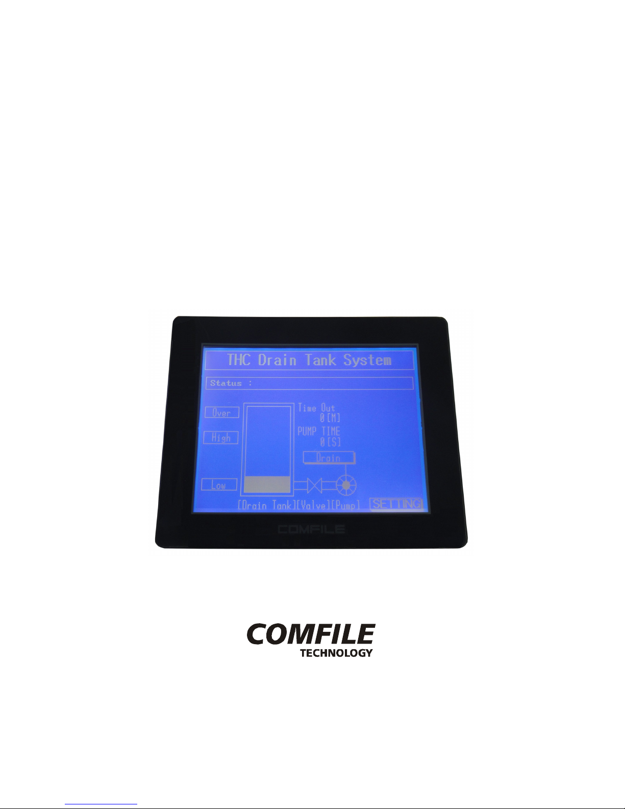
An LCD Touch Screen with an
Integrated BASIC & Ladder Logic Controller
CUTOUCH
CT1820
Last Updated 2015-06-08
www.ComfileTech.com
Comfile Technology, Inc CT1820 User's Manual 1 Of 93
Page 2
Introduction
The CT1820 is the latest, next generation CUTOUCH improving upon the previously released CT1721C.
It is comprised of a built-in CB400 Cubloc core module, a GHB3224 graphical LCD and touch panel, and
includes a wide variety of I/O capabilities.
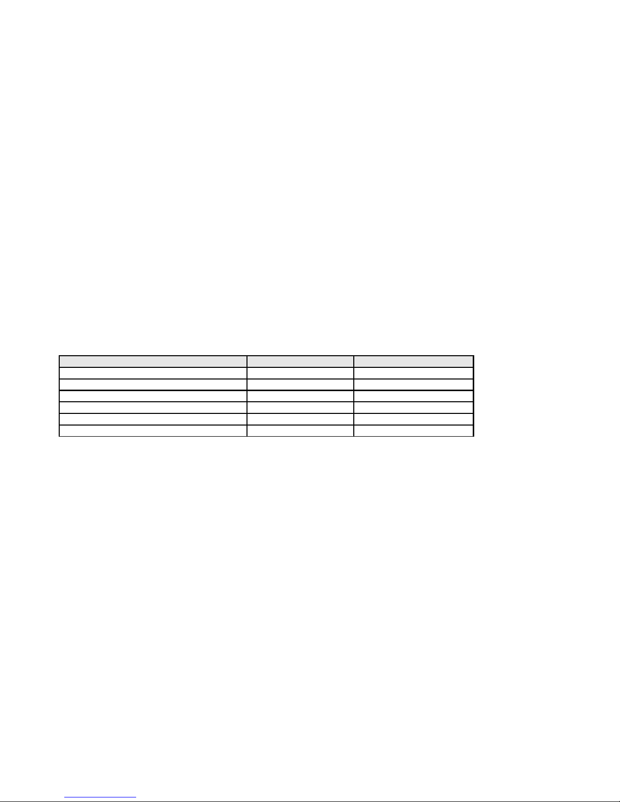
The following shows the how the CT1820 compares to the CT1721C.
1. The LCD is the same.
2. The program memory has been increased: 80KB 200KB
3. The data memory has been reduced: 28KB 7KB
4. FRAM non-volatile memory has been added: 32KB
5. The number of communication ports have been increased: 1 to 3
6. I/O can be extended with Comfile Technology's MODPORT (Field I/O)
7. The enclosure is rated waterproof IP65.
CT1721C CT1820
Program Memory 80KB 200KB
Data Memory 28KB 7KB
FRAM (Non-volatile Memory) None 32KB
Communication Ports 1 3
Total I/O Count 82 50
MODPORT Connectivity Not Supported Supported
CT1721C Backward Compatibility
CT2721C code is not portable to the CT1820.
Comfile Technology, Inc CT1820 User's Manual 2 Of 93
Page 3

Table of Contents
Introduction........................................................................................................................... 2
Chapter 1 Overview.....................................................................................................................4
Product Comparison................................................................................................................ 5
CUTOUCH Overview................................................................................................................ 6
The CT1820's Appearance........................................................................................................7
CUBLOC STUDIO...................................................................................................................10
Downloading Programs to the CT1820.....................................................................................11
Download and Execution........................................................................................................13
Firmware Download.............................................................................................................. 14
CT1820 Start Pack............................................................................................................... 15
Chapter 2 I/O............................................................................................................................16
The CT1820's I/O Ports..........................................................................................................17
PWM Output......................................................................................................................... 20
CT1820's I/O Port Electrical Specifications................................................................................23
Interfacing to Proximity Sensors.............................................................................................24
CT18XX Series' Relays & Registers..........................................................................................26
Chapter 3 Command Reference...................................................................................................27
CT1820 Analog Input............................................................................................................28
CT1820's Non-volatile FRAM...................................................................................................29
Real-Time Clock....................................................................................................................30
Beep (Sound).......................................................................................................................33
RS-232/485 Communication...................................................................................................34
LCD Contrast Adjustment.......................................................................................................35
Chapter 4 Touch Input................................................................................................................ 36
Menu System Library.............................................................................................................37
Menu Commands.................................................................................................................. 37
Processing Touch Input.......................................................................................................... 42
Touch Calibration..................................................................................................................44
Setting the RTC's Date and Time.............................................................................................46
Chapter 5 ModPort I/O Expansion................................................................................................47
Using the CT2820 with the Modport.........................................................................................48
Modport Function Library.......................................................................................................49
Modport Test Program........................................................................................................... 54
Chapter 6 Sample Programs........................................................................................................56
Sample 1.............................................................................................................................57
Sample 2.............................................................................................................................58
Sample 3.............................................................................................................................59
Sample 4: Numeric Input.......................................................................................................60
Sample 5: CuCanvas............................................................................................................. 62
Sample 6: Multi-page Menu Implementation.............................................................................67
Sample 7: Contrast Adjustment..............................................................................................72
Sample 8: RTC Adjustment.................................................................................................... 74
Sample 9: Input Status Monitor..............................................................................................78
Sample 10: Digital Output Control...........................................................................................79
Chapter 7 Panel Mounting........................................................................................................... 82
Dimensions.......................................................................................................................... 83
Panel Cutout.........................................................................................................................84
Panel Mounting Procedure...................................................................................................... 85
Comfile Technology, Inc CT1820 User's Manual 3 Of 93
Page 4

Chapter 1
Overview
Comfile Technology, Inc CT1820 User's Manual 4 Of 93
Page 5
Product Comparison
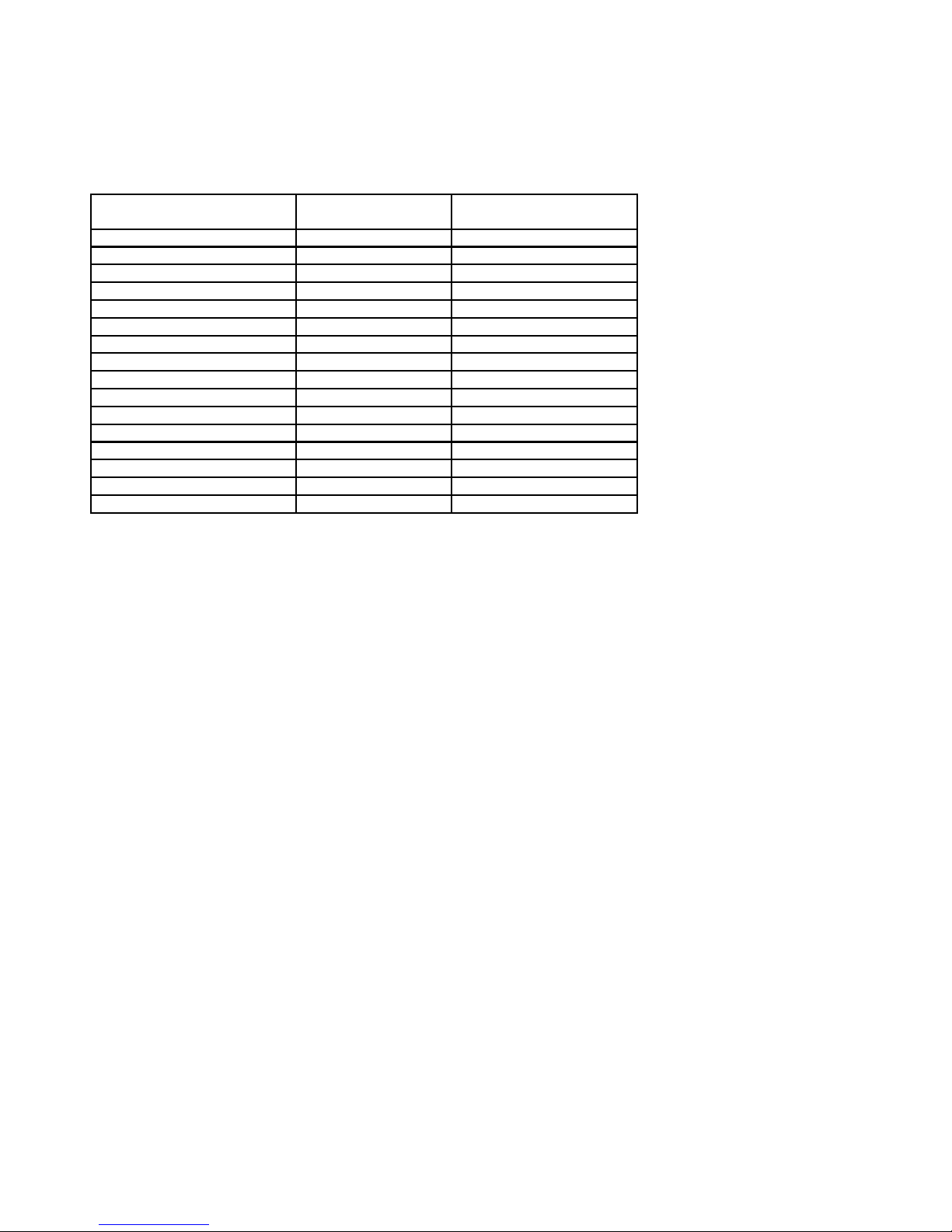
CT1721C CT1820
(New in 2013)
LCD Screen 5.7" Monochrome 5.7" Monochrome
Graphics Engine GHB3224C GHB3224C
Core Module CB290 CB400
Program Memory 80KB 200KB
Data Memory 28KB 7KB
Inputs 32 (24VDC) 22 (24VDC)
Outputs 32 (NPN TR) 20 (NPN TR)
Analog Inputs 8 8
High Speed Counter 2 None
PWM 6 3
External Interrupts 4 None
Total 82 50
Front Panel (IP65 Rating) No Yes
Download Cable DSUB 9-PIN 3-PIN
Battery Backup Yes No (Use FRAM Instead)
RTC and RTC Battery Built-in Built-in
The CT1820 does not contain a backup battery for the data memory. To retain data between power
cycles, please use the FRAM non-volatile memory instead.
Comfile Technology, Inc CT1820 User's Manual 5 Of 93
Page 6
CUTOUCH Overview
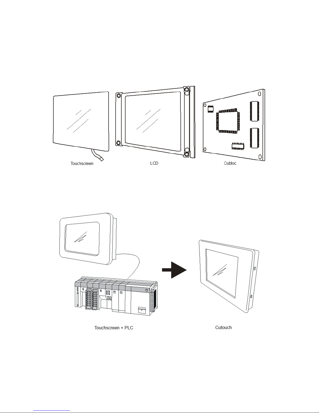
The Cutouch is a Cubloc Core with an integrated LCD and Touchscreen. It can be programmed to draw
graphics (lines, circle, etc...) on the LCD and to read the coordinates of touch inputs from a user.
The Cutouch provides a new approach to employing a touchscreen and PLC in the automation field. The
cost of a separate touchscreen, LCD, and PLC can be significant, but the Cutouch provides and
integrated solution at a relatively low cost..
Futhermore, the Cutouc is programmed is BASIC, a language that is quite easy to learn and use.
Comfile Technology, Inc CT1820 User's Manual 6 Of 93
Page 7
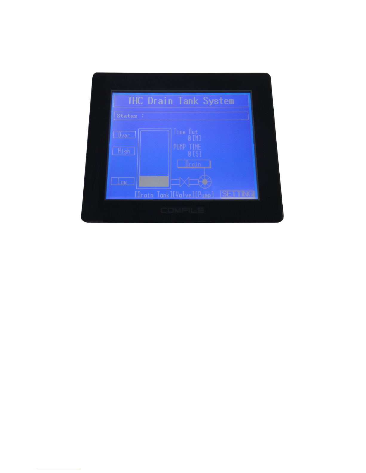
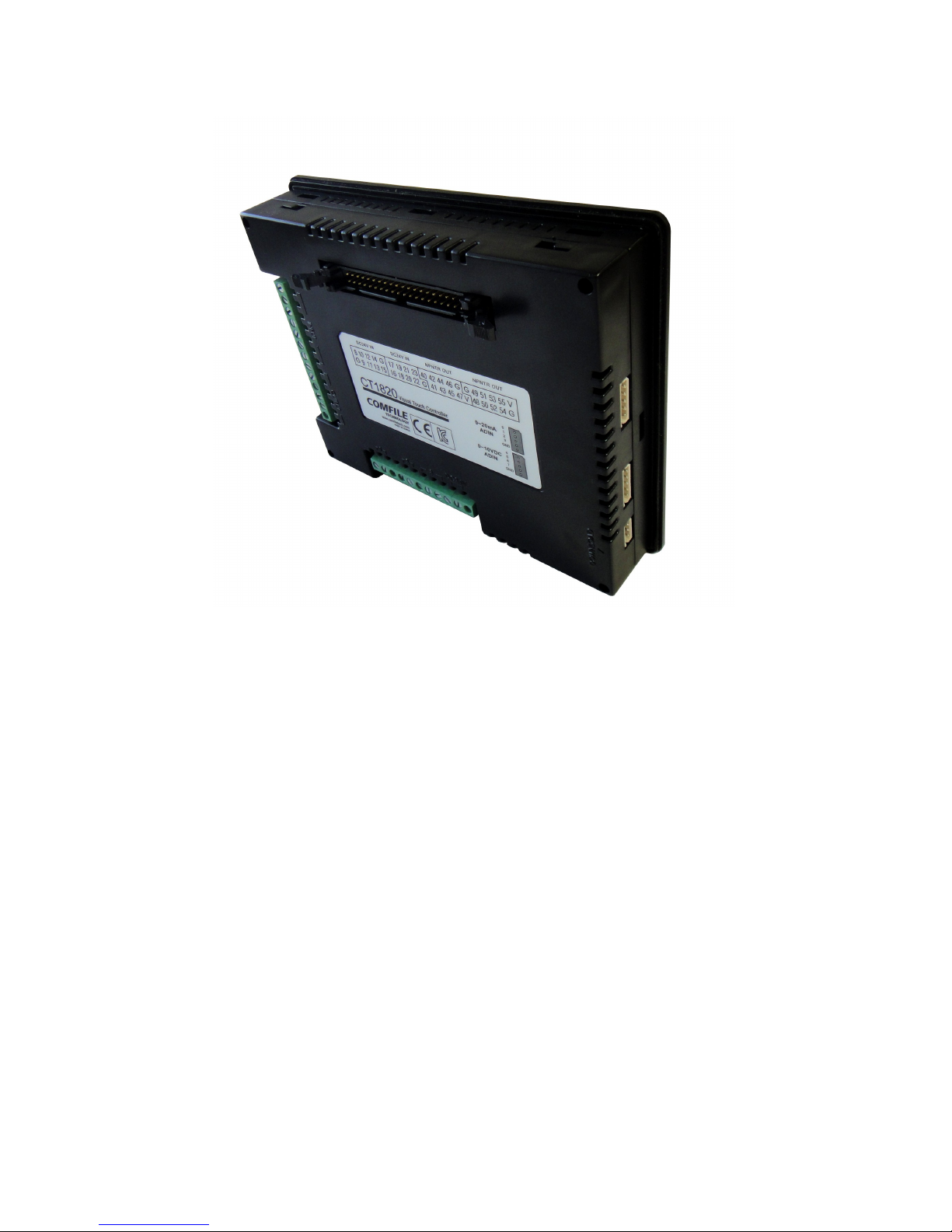
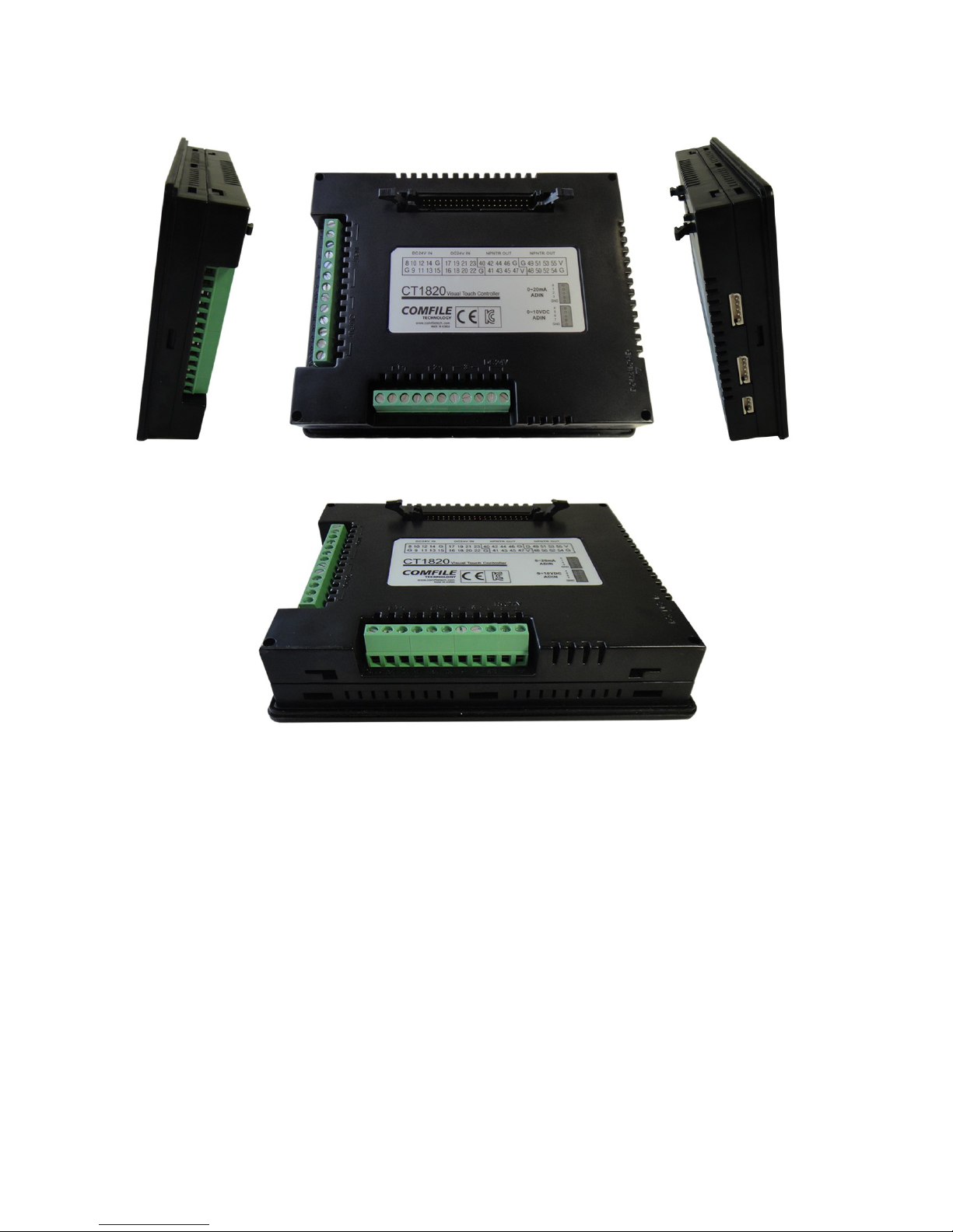
The CT1820's Appearance
Comfile Technology, Inc CT1820 User's Manual 7 Of 93
Page 8
Comfile Technology, Inc CT1820 User's Manual 8 Of 93
Page 9
Comfile Technology, Inc CT1820 User's Manual 9 Of 93
Page 10
CUBLOC STUDIO
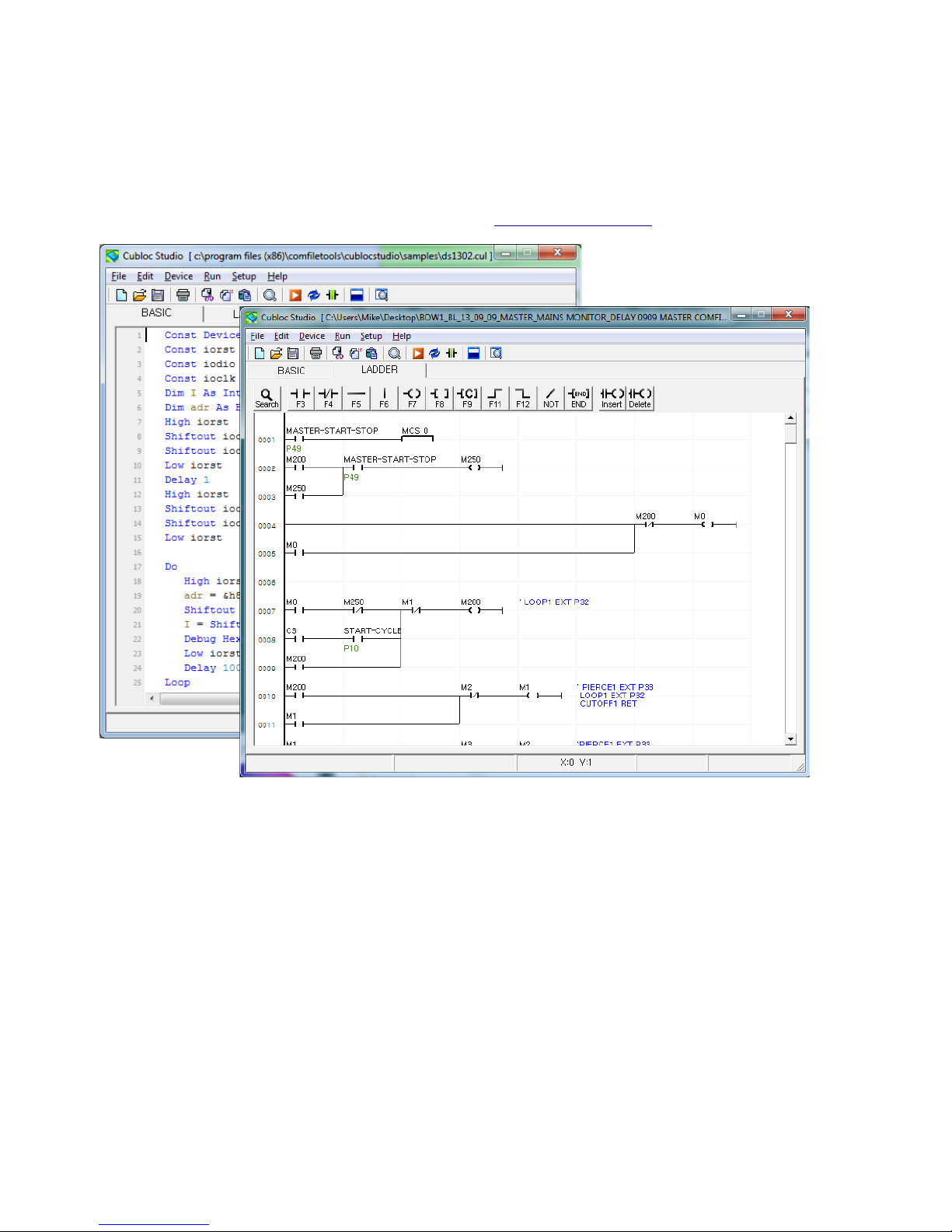
Cubloc Studio is the Integrated Development Environment used to program the CT1820 in both BASIC
and Ladder Logic. It is a free download available from www.ComfileTech.com.
* To program the CT1820, be sure to #include "CT18XX" at the top of the source file.
Comfile Technology, Inc CT1820 User's Manual 10 Of 93
Page 11
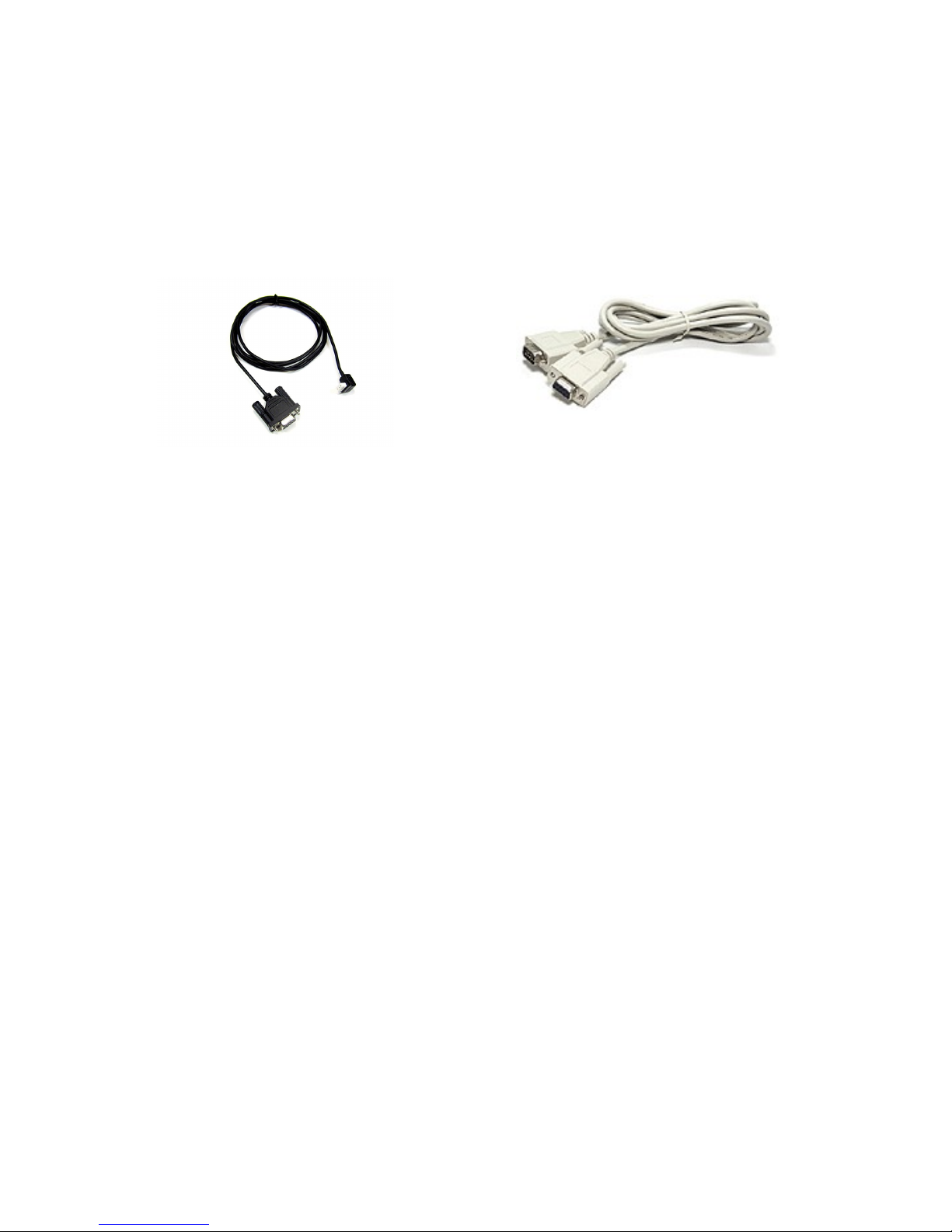
Downloading Programs to the CT1820
After authoring and compiling source code using Cubloc Studio, it can be downloaded to the CT1820 via
the host PC's RS-232 serial port for execution. Once the program is downloaded to the CT1820, it will
remain in in the CT1820's read-only memory even between power cycles. First, the CT1820's download
cable must be used to connect the CT1820 to the host PC.
CT1820 Download Cable CT1721C Download Cable
The download cable is not included as only one is needed to download to many devices. Please be sure
to add a download cable to your first purchase. The host PC end of of the download cable is a DB-9
female connector and the CT1820 end is a 3-pin Molex SPOXTM 5268 female connector.
If the host PC does not have any built-in RS-232 serial ports, a USB-to-serial adapter can be used.
Comfile Technology, Inc CT1820 User's Manual 11 Of 93
Page 12

Comfile Technology, Inc CT1820 User's Manual 12 Of 93
Page 13
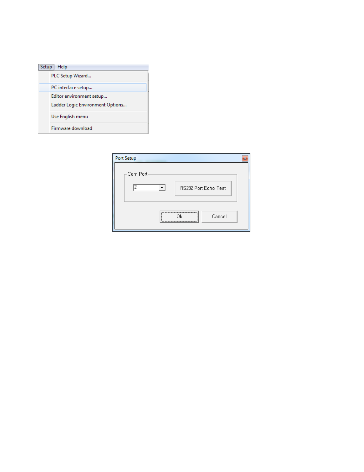
After the host PC is connected to the CT1820 via the download cable, open Cubloc Studio and choose
"Setup" "PC int→ erface setup..." from the menu.
Select the host PC's serial port (Com Port) that is connected to the CT1820.
Comfile Technology, Inc CT1820 User's Manual 13 Of 93
Page 14
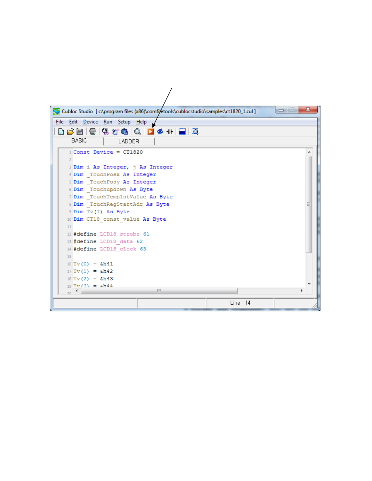
Download and Execution
In Cubloc Studio, choosing "Run" from the menu (or typing CTRL-R) will compile and download the
currently open program to the CT1820.
Once a program is compiled and downloaded to the CT1820, it cannot be retrieved and decompiled back
into source code form.
Comfile Technology, Inc CT1820 User's Manual 14 Of 93
Clicking this icon will save the source code,
compile, and initiate downloading
Page 15
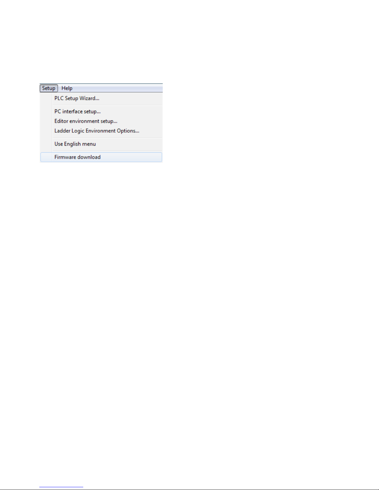
Firmware Download
If downloading does not go well, it may be helpful to download the firmware.
Downloading the firmware will restore the CT1820 to its default factory state. All user programs will be
lost.
The firmware is essentially the CT1820's operating system. At the time of manufacturing, the latest
available firmware is downloaded to the CT1820.
If new firmware is released, a new version of Cubloc Studio will also be released. When downloading
with the latest version of Cubloc Studio, a prompt may appear to update the CT1820's firmware.
Comfile Technology, Inc CT1820 User's Manual 15 Of 93
Page 16

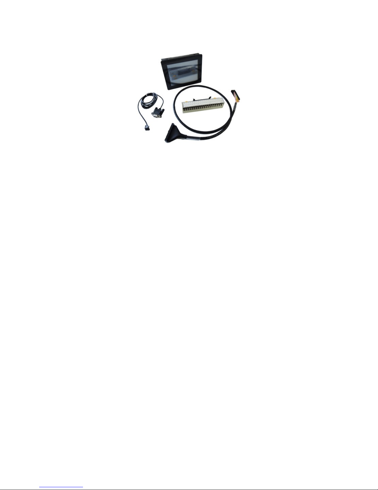
CT1820 Start Pack
The CT1820 Start Pack is recommended for initial CT1820 purchases. It contains all the necessary
accessories to take full advantage of the CT1820's features.
Comfile Technology, Inc CT1820 User's Manual 16 Of 93
Page 17
Comfile Technology, Inc CT1820 User's Manual 17 Of 93
Page 18

Contents: CT1820, 3-pin download cable, 1-meter 40-pin connection cable, 40-pin terminal block.
NOTE: The CT1820 Start Pack does not include a USB-to-serial adapter/cable. If your host PC does not
have a built-in RS-232 serial port, you may need to buy a USB-to-serial adapter/cable separately.
Comfile Technology, Inc CT1820 User's Manual 18 Of 93
Page 19

Chapter 2
I/O
Comfile Technology, Inc CT1820 User's Manual 19 Of 93
Page 20
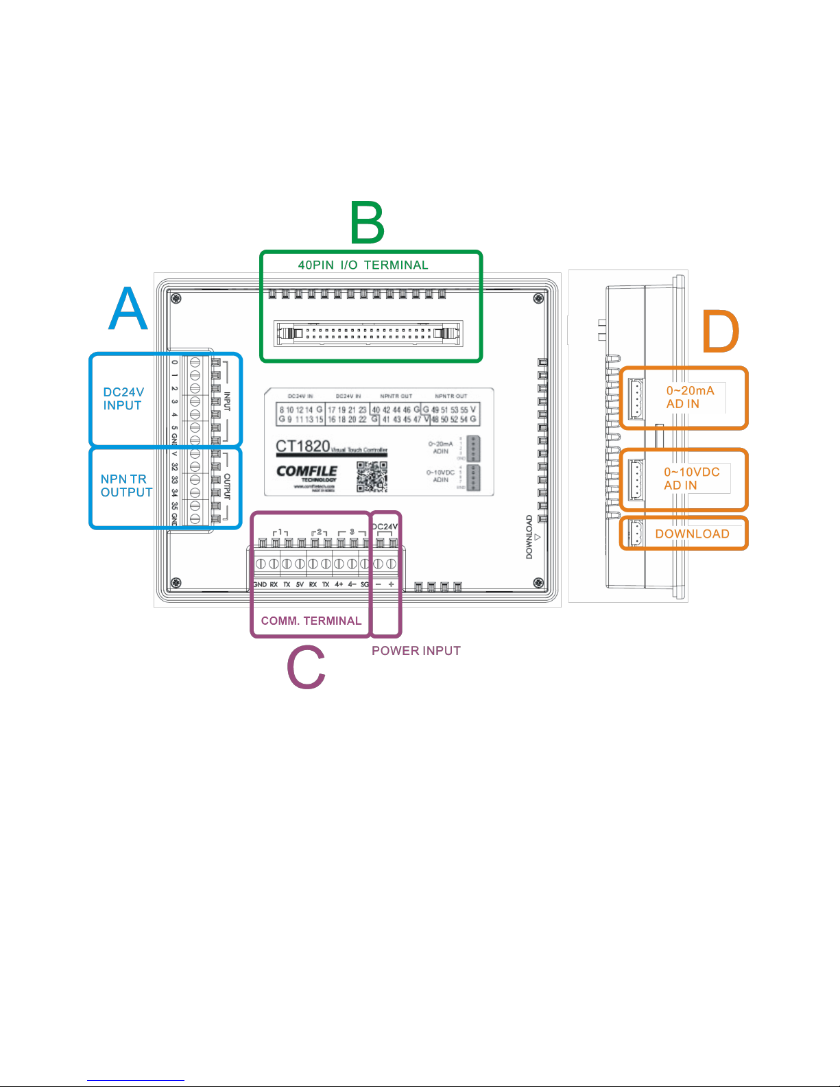
The CT1820's I/O Ports
The following image shows the location of the various I/O ports on the back and side of the CT1820.
Please use a 24VDC power supply (20~25VDC) and pay careful attention to the polarity.
Power consumption of the CT1820 with no I/O load is approximately 3 watts.
*Please do not attempt to disassemble the the CT1820, as it can result in unintentional
damage to the the LCD and other components. Products that have been tampered with will
not receive warranty or service benefits.
Comfile Technology, Inc CT1820 User's Manual 20 Of 93
Page 21
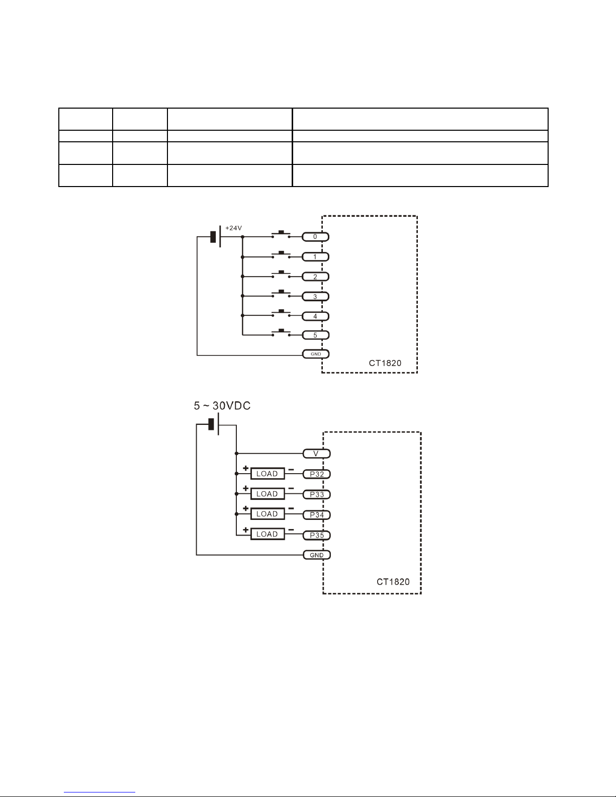
A. The Digital Input/Output ports (A) contain 6 24VDC inputs and 4 NPN transistor outputs.
Pin
Number
Port
Number
Input/Output Description
0 ~ 5 0 Input 20~28VDC for active high
32 ~ 35 4 Output (Current Sink) NPN transistor output. 'On' creates a path to
ground.
V Built-in protection diode If the load is a relay, this must be connected to the
positive terminal.
The input circuit is illustrated below.
The output circuit is illustrated below.
If the load is inductive, such as a relay, please be sure to connect the positive terminal to the V pin.
This can help to eliminate sparking when switching.
*Warning. Please refrain from wiring while power is connected to avoid shorts and
subsequent damage to the unit.
Comfile Technology, Inc CT1820 User's Manual 21 Of 93
Page 22
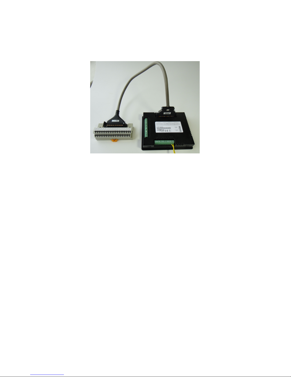
B. This is a 40-pin terminal block connector with 16 inputs and 16 outputs, as depicted in the
following image. Cables and terminal block are sold separately. The Start Pack includes a 1-meter cable,
but 0.5-meter, 2-meter, and 5-meter cables are also available.
Comfile Technology, Inc CT1820 User's Manual 22 Of 93
Page 23
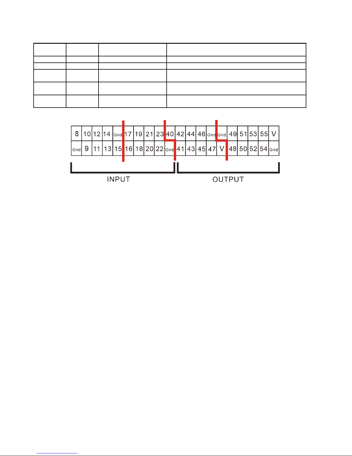
Pin
Number
Port
Number
Input/Output Description
8 ~ 15 1 Input 20~28VDC for active high
16 ~ 23 2 Input 20~28VDC for active high
40 ~ 47 5 Output (Current Sink) NPN transistor output, 'On' creates a path to
ground
48 ~ 55 6 Output (Current Sink) NPN transistor output, 'On' creates a path to
ground
V Built-in protection
diode
If the load is a relay, this must be connected to
the positive terminal.
Pin assignments are as follows:
The input and output configuration is described in the preceding pages.
*Please do no use unassigned pins (e.g. Low 56 'This pin is not assigned)
*Warning. Please refrain from wiring while power is connected to avoid shorts and
subsequent damage to the unit.
Comfile Technology, Inc CT1820 User's Manual 23 Of 93
Page 24
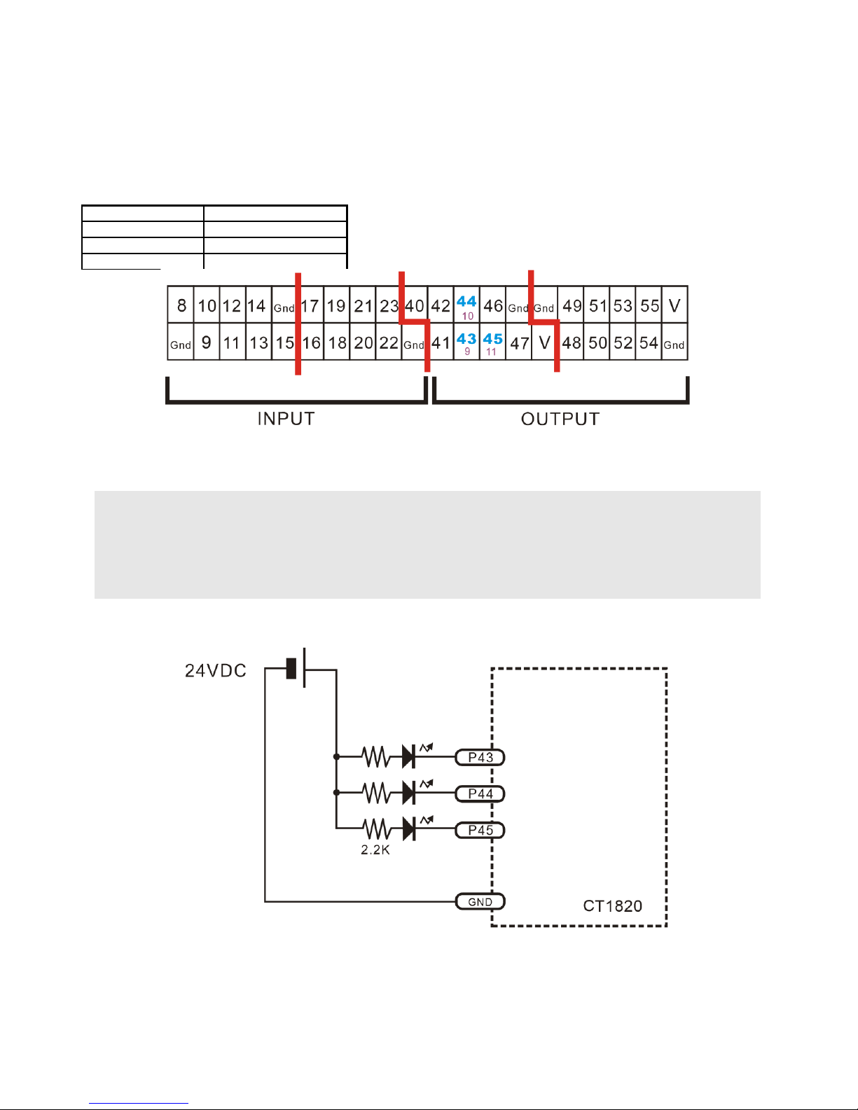
PWM Output
The CT1820 has 3 PWM outputs. They are available in the 40-pin I/O port as pins 43, 44, and 45.
Pin Number PWM Channel
43 9
44 10
45 11
The following program outputs pulses on channels 9, 10, and 11. The PWMOff command can be used to
stop a PWM channel.
Low 43
Low 44
Low 45
Pwm 9,950,1024
Pwm 10,750,1024
Pwm 11,450,1024
The PWM output is an open-collector transistor output. It can be used in the configuration below to
control the brightness of an LED.
Comfile Technology, Inc CT1820 User's Manual 24 Of 93
Page 25
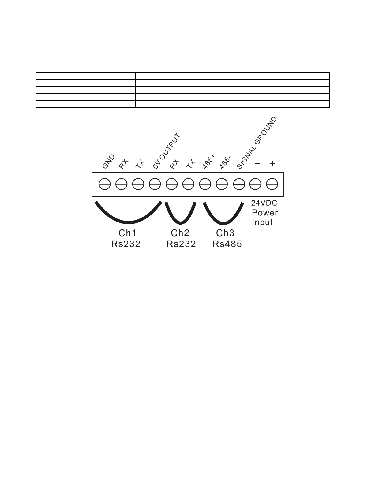
C. This port contains the RS-232/485 communication channels and the main power supply
connection.
Channel Terminals Description
RS-232 Channel 1 RX, TX Channel 1
RS-232 Channel 2 RX, TX Channel 2
RS-485 Channel 3 4+, 4-, SG Channel 3, Modport or other RS-485 connection
5V 5V 5V (0.25A) Output, generated internally by the CT1820.
Comfile Technology, Inc CT1820 User's Manual 25 Of 93
Page 26
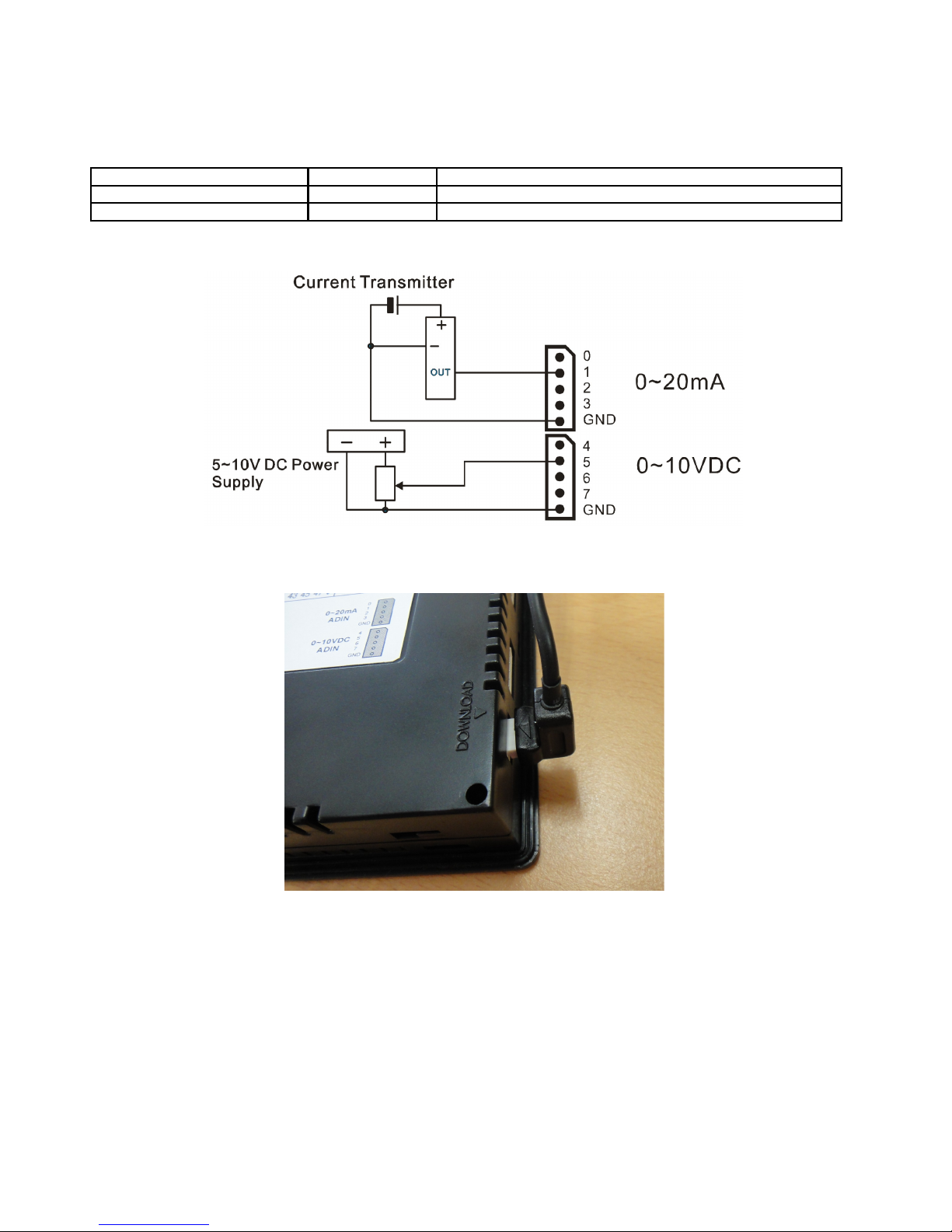
D. These ports consist of the analog input ports and the download port.
ADC Channel Number Input Type Description
0 ~ 3 0 ~ 20mA For reading current signals
4 ~ 7 0 ~ 10VDC For reading voltage signals
Warning: Please do not exceed the specified current and voltage ranges, or the device may become
damanged.
Use the download port to connect the 3-pin download cable as shown below.
Comfile Technology, Inc CT1820 User's Manual 26 Of 93
Page 27
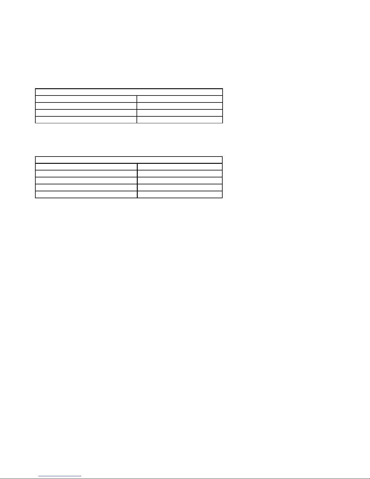
CT1820's I/O Port Electrical Specifications
All input pins are 24VDC inputs only.
Input Specifications
Input Voltage Range 20 ~ 28VDC
Recommended Operating Voltage 0 or 24VDC
Recommended Operating Current At least 2mA
Input Impedance 2.2KΩ @ 24VDC
All output pins are NPN transistor outputs.
Output Relay Specifications
Output Voltage Range 5 ~ 30VDC
Recommended Operating Voltage 6 ~ 27VDC
Maximum Switching Frequency 100Hz
Maximum Current 250mA / Pin
Minimum Current 10mA / Pin
High-speed counter and external interrupt features are not supported.
Comfile Technology, Inc CT1820 User's Manual 27 Of 93
Page 28
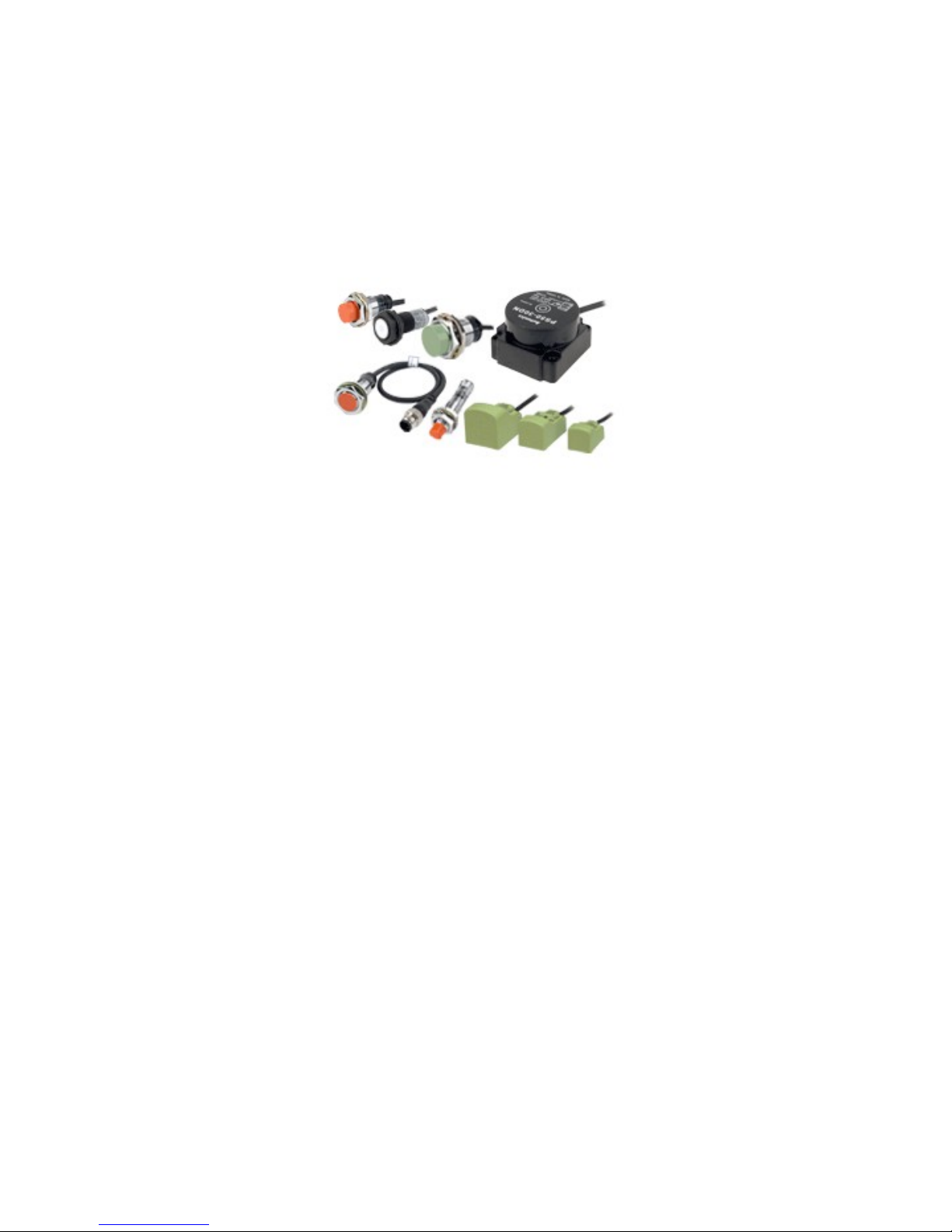
Interfacing to Proximity Sensors
Proximity sensors can be used to detect the existence, movement, and displacement of objects without
any physical contact with the object. They are used quite often in the field of automation.
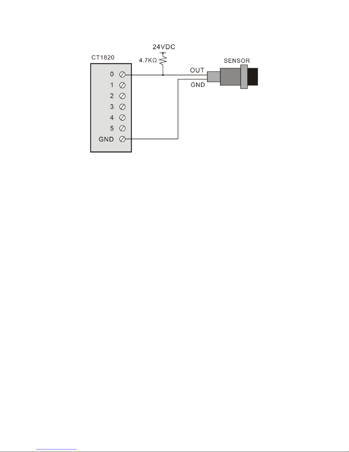
The following instructions show how to connect the 2-wire and 3-wire type
DC 2-Wire Model
Sensor output connected in reverse
Comfile Technology, Inc CT1820 User's Manual 28 Of 93
Page 29
Comfile Technology, Inc CT1820 User's Manual 29 Of 93
Page 30
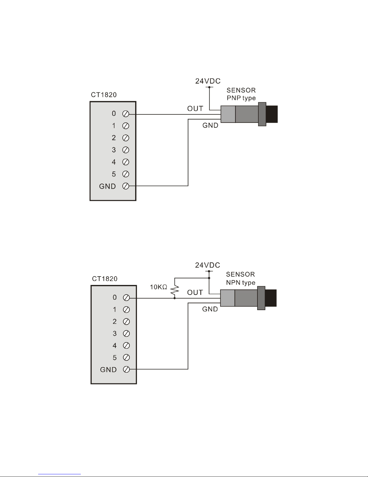
DC 3-Wire Model (PNP type)
Sensor output connected in reverse
DC 3-Wire Model (NPN type)
Sensor output connected in reverse
Comfile Technology, Inc CT1820 User's Manual 30 Of 93
Page 31
CT18XX Series' Relays & Registers
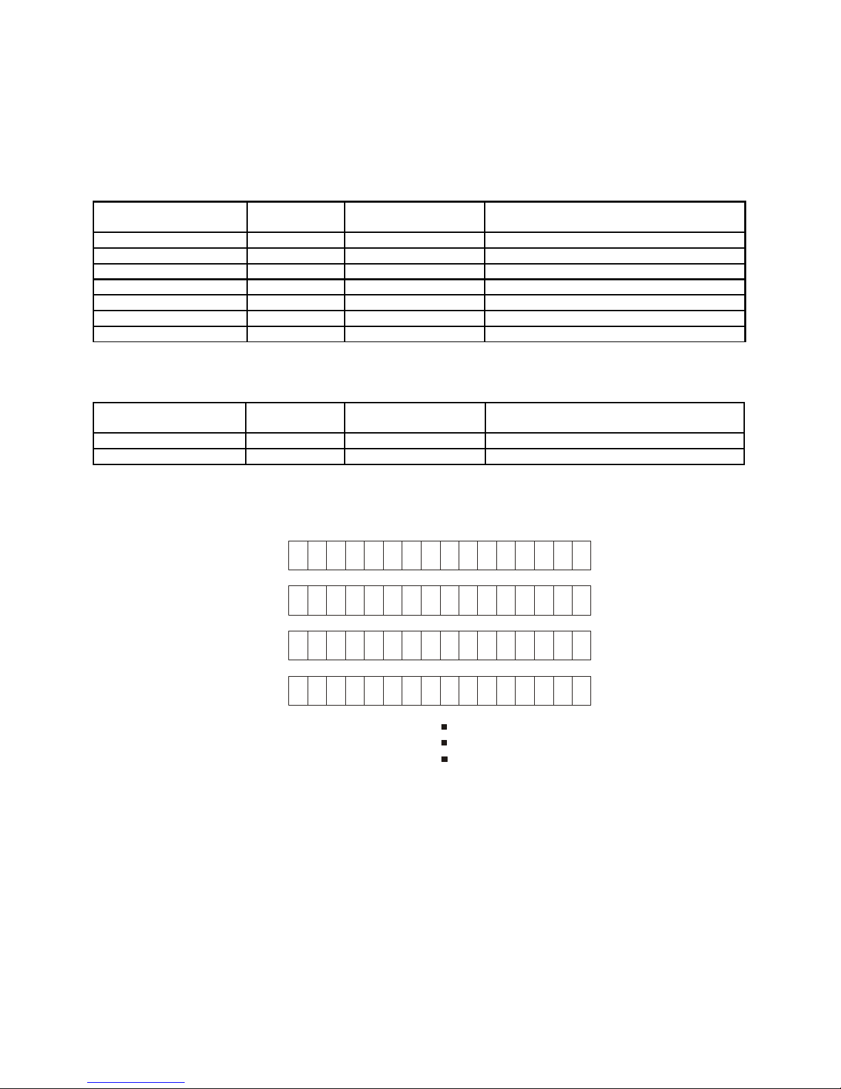
The following lists the various relays and registers available for use in Ladder Logic.
Relay/Register
Designation
Range Units Feature
P - Input Relays P0~P31 1 bit For interfacing with external devices
P - Output Relays P32~P63 1 bit For interfacing with external devices
M - Internal Relays M0~M511 1 bit For saving internal status
F - Special Relays F0~F127 1 bit System status
T - Timer T0~T99 16 bits (1 word) For timers
C - Counter C0~C49 16 bits (1 word ) For counters
D - Data Region D0~99 16 bits (1 word) For Data storage
P, M, and F are accessed in bit units while T, C, and D are accessed in word units. However, P, M, and F
can also be accessed in word units using WP, WM, and WF respectively.
Relay/Register
Designation
Range Units Feature
WP WP0~7 16 bits (1 word) For accessing P in word units
WM WM0~WM63 16 bits (1 word) For accessing M in word units
Lower numbered designations are stored in the lower significant bits and higher numbered designations
are stored in higher significant bits. For example, the P region would appear as follows when accessed
as WP.
P0
WP0
WP1
WP2
WP3
P15
P31 P16
P32
P48
P47
P63
Comfile Technology, Inc CT1820 User's Manual 31 Of 93
Page 32

Chapter 3
Command Reference
Comfile Technology, Inc CT1820 User's Manual 32 Of 93
Page 33

CT1820 Analog Input
The CT1820 has 8 analog input channels.
ADIn( )
variable = ADIn (channel)
variable : Variable to which the results will be stored
channel : Analog input channel (Not the I/O pin number) from which to read
Reads the value from analog input channel channel, and stores the result to variable.
The CT1820 8 10-bit analog input channels:
• Channels 0~3 are 0~20mA current analog inputs.
• Channels 4~7 are 0~10VDC voltage analog inputs.
A = ADIn(4) ' Read from analog input channel 4
Comfile Technology, Inc CT1820 User's Manual 33 Of 93
Page 34

CT1820's Non-volatile FRAM
Data that needs to be retained between power cycles can be stored in the CT1820's non-volatile FRAM.
FramWrite
FramWrite address, data
address : Address to write the data to
data : Store 1 byte of data (variables or constants)
Stores one byte of data, data, to the FRAM at address, address.
Data can be stored from addresses 0~&H7FFF, a total of 32KB. The data will be retained between power
cycles and no delay is required after a write.
FramWrite 14, &HFF ' Writes &HFF to address 14
FramRead( )
variable = FramRead (address)
variable : Variable to which the results will be stored
address : Address to read the data from
Reads one byte of data from the FRAM at address address, and stores the result in variable.
A = FramRead(14) ' Reads one byte of data from address 14
Comfile Technology, Inc CT1820 User's Manual 34 Of 93
Page 35
Real-Time Clock
The CT1820 has a real-time clock (RTC) that can be used to measure calendar date and time. The
RTCWrite command is used set the RTC's date and time, and the RTCRead command is used to read the
RTC's current date and time.
RTCRead( )
Variable = RTCRead( address )
variable : The variable to which the result will be stored
address : RTC's register address
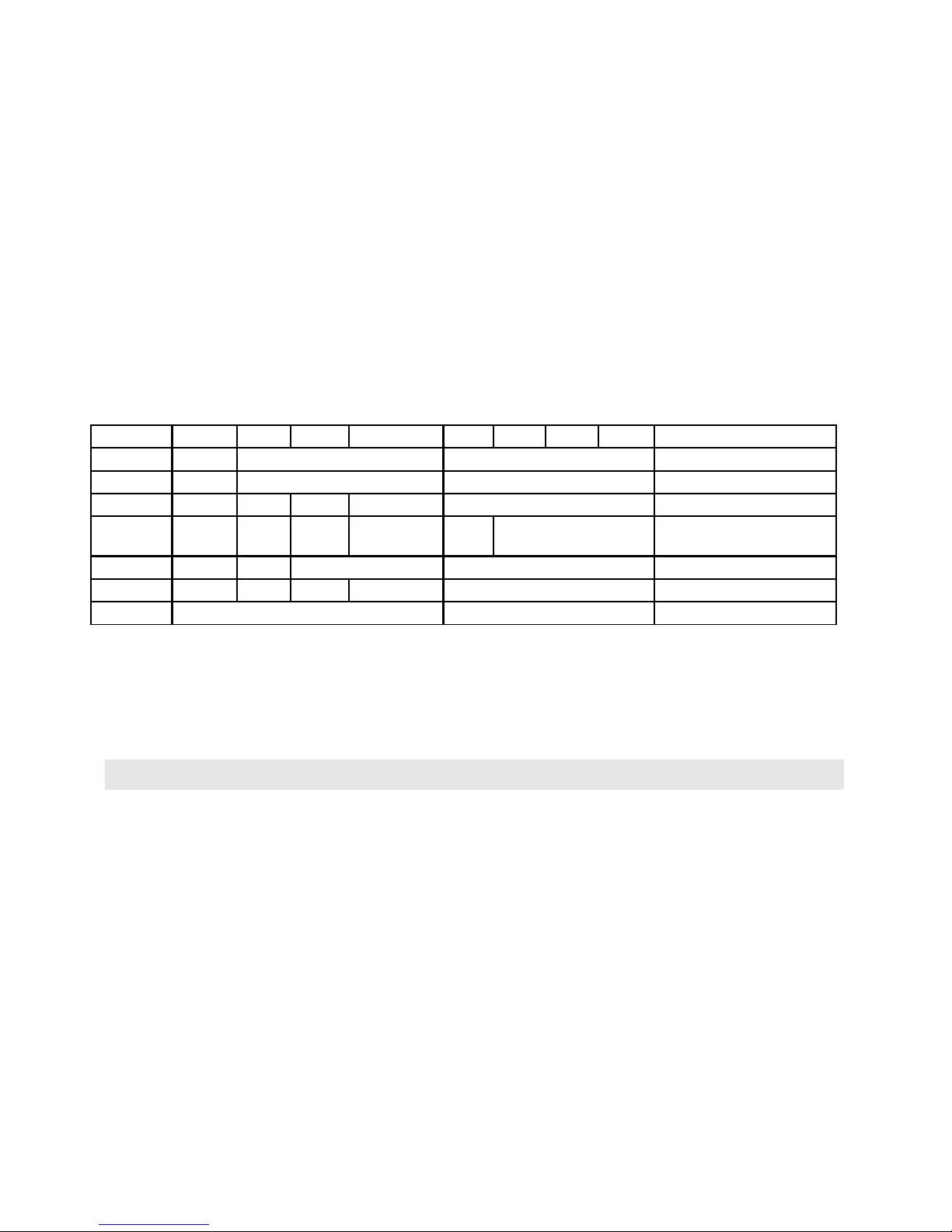
The following details the format of the data retrieved from the RTC.
Address BIT7 BIT6 BIT5 BIT4 BIT3 BIT2 BIT1 BIT0 Feature & Range
0 0 Seconds (101) Seconds (100) Seconds (0~59)
1 0 Minutes (101) Minutes (100) Minutes (0~59)
2 0 12/24 AM/PM Hours (101) Hours (100) Hours (0~23)
3 0 0 0 0 0 Day of the week 1~7
(1=Sun. ~ 7=Sat.)
4 0 0 Day (101) Day (100) Day (1~31)
5 Century 0 0 Month (101) Month (100) Month (1~12)
6 Year (101) Year (100) Year (0 ~ 99)
Address 0 stores the number of seconds in the RTC's current time. The data is stored as binary coded
decimal (BCD), so the first 4 bits store the 101 digit while the lower 4 bits store the 100 digit
Therefore, if address 0 stores the value 0001 00012, then then the number of seconds is 11, not 17.
Displaying the value in hexadecimal, is one way to show the value in decimal as illustrated in the
example below.
A = RTCRead(0)
Debug Hex2 A,Cr
Comfile Technology, Inc CT1820 User's Manual 35 Of 93
Page 36
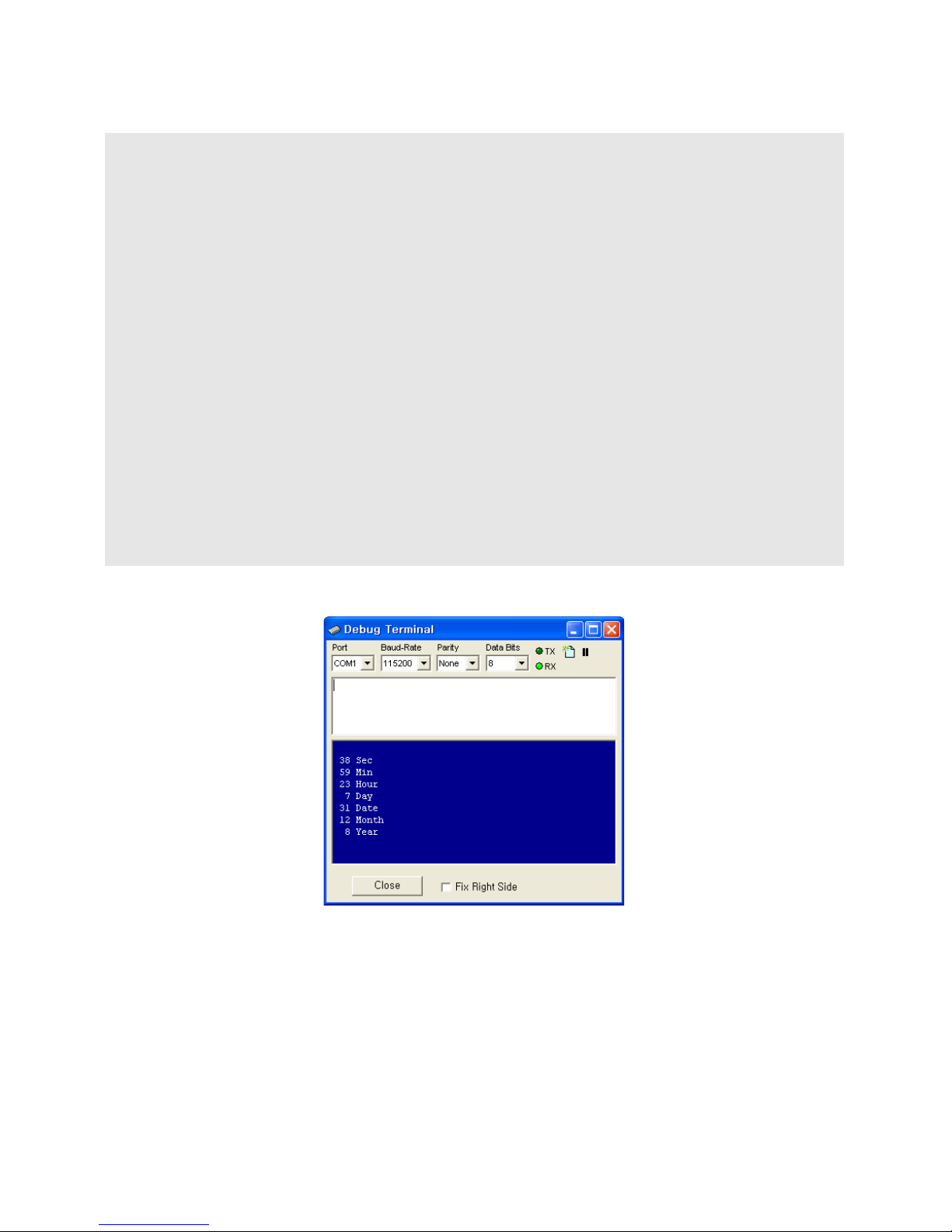
#include "CT18XX"
Dim i As Integer
Wait 100
RTCWrite 0,&h20 ' Sec
RTCWrite 1,&h59 ' Min
RTCWrite 2,&h23 ' Hour 24h
RTCWrite 3,&h7 ' day 1-7, 1=Sun, 2=Mon, 3=Tue, 4=Wed, 5=Thu, 6=FRI, 7=SAT
RTCWrite 4,&h31 ' Date
RTCWrite 5,&h12 ' Month
RTCWrite 6,&h08 ' Year
Do
i = RTCRead(0)
Debug Goxy,1,1,Hex2 i, " Sec"
i = RTCRead(1)
Debug Goxy,1,2,Hex2 i, " Min"
i = RTCRead(2) And &h3f
Debug Goxy,1,3,Hex2 i, " Hour"
i = RTCRead(3)
Debug Goxy,1,4,Hex2 i, " Day"
i = RTCRead(4)
Debug Goxy,1,5,Hex2 i, " Date"
i = RTCRead(5)
Debug Goxy,1,6,Hex2 i, " Month"
i = RTCRead(6)
Debug Goxy,1,7,Hex2 i, " Year"
Wait 500
Loop
The results of this example are displayed in the Cubloc Studio debug terminal.
Comfile Technology, Inc CT1820 User's Manual 36 Of 93
Page 37
RTCWrite
RTCWrite address, data
address : RTC's register address (see table for RTCRead)
data : The data to store (variable or constant)
Stores Data to the RTC's register address, Address, effectively setting the RTC's current date and time.
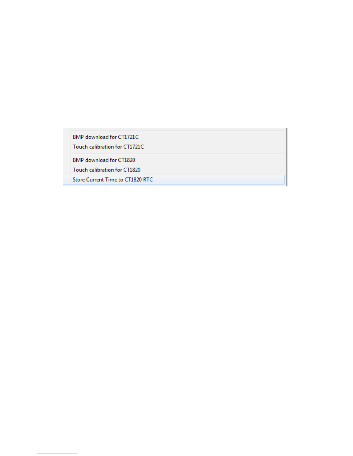
The RTC's current date and time can be set from a PC within Cubloc Studio. From Cubloc Studio's
menu, choose "File" "Store Current Time to CT1→ 820 RTC", and the PC's current date and time will be
stored to the CT1820's RTC.
The CT18XX series' RTC is battery powered, so in between power cycles, the RTC's date and time
continue to increment. However, the RTC is not 100% accurate, and if used for an extended period of
time, a drift may become apparent, and will need to be re-synchronized with a current time source.
Comfile Technology, Inc CT1820 User's Manual 37 Of 93
Page 38

Beep (Sound)
The CT1820 has a built-in buzzer than can be used to generated audio feedback in the form of beeps
and tones.
CT18Beep
CT18Beep value
value : Integer variable or constant (less than 255).
Generates a beep. To generate an adequate feedback beep on a touch event, use a value between 20
and 50.
Comfile Technology, Inc CT1820 User's Manual 38 Of 93
Page 39

RS-232/485 Communication
The CT1820 has two RS-232 serial ports and one RS-485 serial port.
Note: It is recommended to not analyze the data from the serial port as it's being received because the
CT1820 can process data much faster than the serial port can receive it. Rather, it would be best to
leverage the CT1820's built-in Modbus RTU protocol. The Modbus RTU protocol will handle the data
processing so the user doesn't have to.
OpenCom
OpenCom channel, baudRate, settings, receiveSize, sendSize
channel : The RS-232 channel to use
baudRate : The baud rate
settings : Serial settings (data bits, parity, and stop bits)
receiveSize : Receive buffer size (Maximum 1024 bytes)
sendSize : Send buffer size (Maximum 1024 bytes)
Opens a serial port for use. This command called before any data can be read from or written to the
serial port.
Opencom 1,115200,3,80,80 ' Open Channel 1
By #include "CT18XX", channel 3 can be used for RS-485 for communicating with RS-485 peripherals
such as Comfile Technology's ModPort field I/O controller. Be sure to use Set RS485 to set pin 71 as the
transmit enable pin.
' Configure the serial port at the beginning of the source file
Opencom 3,57600,3,50,50
Set Rs485 3,71 ' Set Pin 71 as the transmit enable pin
The Set RS232 command can be used to change the serial settings
#include "CT18XX"
Set Rs232 3,115200,3 ' Change channel 3's serial settings
Comfile Technology, Inc CT1820 User's Manual 39 Of 93
Page 40

LCD Contrast Adjustment
The CT1820's screen contrast is adjustable through software.
CT18Contrast
CT18Contrast value
value : Integer variable or constant (0 ~ 255)
Sets the LCD's contrast. For best results, set between 130 and 160. This value is stored in the EEPROM
at address &HFFF. The following program shows how this value can be read and corrected to ensure an
appropriate value.
Dim Cont_value As Byte
Cont_value = EERead(&hfff, 1)
If Cont_value < 100 Or Cont_value > 200 Then ' Ensure an appropriate value
Cont_value = 150
EndIf
CT18Contrast Cont_value
Comfile Technology, Inc CT1820 User's Manual 40 Of 93
Page 41

Chapter 4
Touch Input
Comfile Technology, Inc CT1820 User's Manual 41 Of 93
Page 42
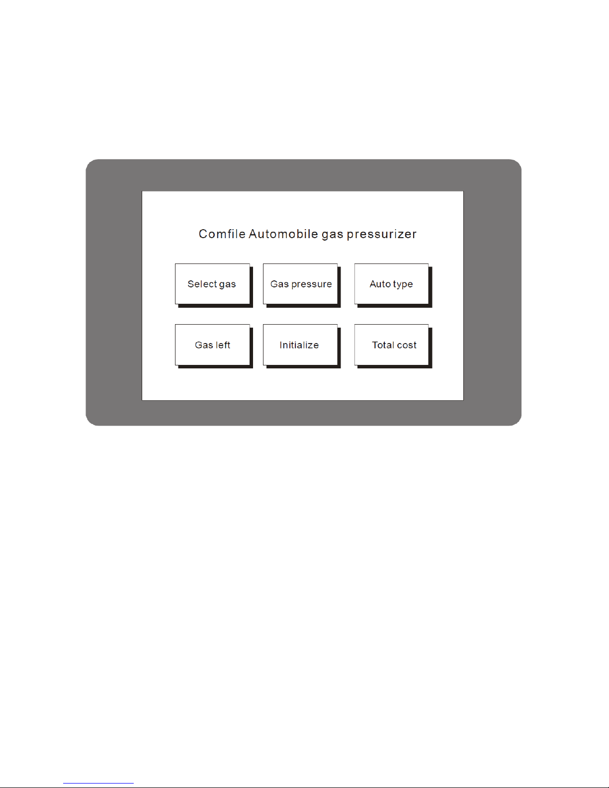
Menu System Library
The CT1820 includes additional commands that can be used to create and manipulate menus. With this
menu library, it is easy to create a user interface like that depicted below.
Menu Commands
Up to 50 menu buttons can be created on the CT1820. Each call to the MenuSet command creates a
new button with an individual style, location, and size. The MenuTitle command can be used to give
the menu button a caption, and the MenuCheck commands can be used to determine if a button has
been touched.
Each button's status can be changed at any time by calling the MenuSet command, and each button can
be given a different function on a different screen, resulting in virtually an unlimited number of menus
and buttons.
Comfile Technology, Inc CT1820 User's Manual 42 Of 93
Page 43
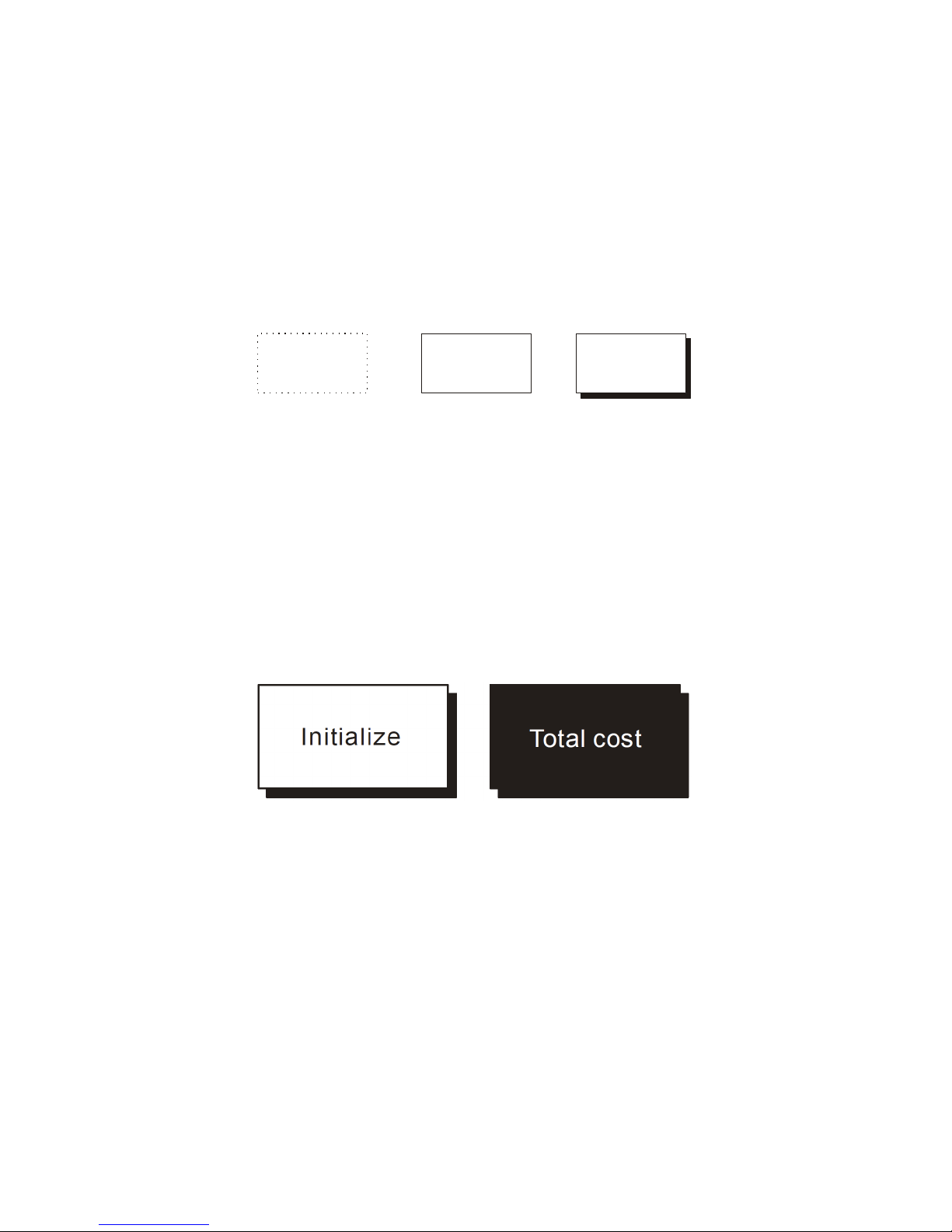
MenuSet
MenuSet index, style, x1, y1, x2, y2
index : Menu index number
style : Button style ( 0 ~ 2)
x1, y1, x2, y2 : Menu button's screen coordinates
index value must be a number from 0 through 49. style specifies the style of the button as shown
below.
0 1 2
x1, y1, x2, y2 are the x and y screen coordinates of the upper-left and lower-right corners of the
button, respectively.
MenuReverse
MenuReverse index
index : Menu index number
This command causes the menu button identified by index to have it's colors reversed for visual
feedback. This is useful to provide visual feedback to a user, indicating that a menu button has been
touched.
MenuSetClear
MenuSetClear
Clears all menu buttons on the screen. Call this before creating a new menu. This commands is not
available in the CT1721C.
Comfile Technology, Inc CT1820 User's Manual 43 Of 93
Page 44
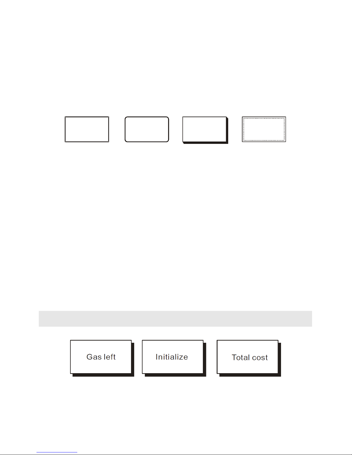
MenuSet2
MenuSet2 index, style, x1, y1, x2, y2
index : Menu index number
style : Button style ( 0 ~ 3)
x1, y1, x2, y2 : Menu button coordinates
This command is exactly the same as the MenuSet command, but can draw different styles. This
command is not available in the CT1712C.
0
1
2 3
MenuReverse2
MenuReverse2 index, style
index : Menu index number
style : Button style
This command is exactly the same as the MenuReverse command, but it used for buttons declared with
the MenuSet2 command. This command is not available in the CT1712C.
MenuTitle
MenuTitle index, x, y, string
index : Menu index number
x, y : Coordinates of the caption from the button's top-left corner
string : The caption to display
MenuSet only draws the button itself. Use the MenuTitle command to set the button's caption.
MenuTitle 0,13,13,"Gas Left"
MenuTitle 1,16,13,"Initialize"
MenuTitle 2,13,13,"Total Cost"
Comfile Technology, Inc CT1820 User's Manual 44 Of 93
Page 45

MenuCheck( )
variable = MenuCheck( index, touchX, touchY)
variable : Variable to which the results will be stored (1 = touched, 0 = not touched)
index : Menu index number
touchX : X coordinate of touch
touchY : Y coordinate of touch
Use this function to determine if a menu button has been touched. touchX and touchY are the x and y
coordinates of where the user touched the screen.
If the coordinates of the touch lie within the area of the button, 1 is returned, otherwise 0 is returned.
If Menucheck(0,TX1,TY1) = 1 Then
Menureverse 0
Beep 18,180
End If
Menu( )
variable = Menu(index, coordinate)
variable : Variable to store the results (1 = selected, 0 = unselected)
index : Menu index number
coordinate : Coordinate to check (0=x1, 1=y1, 2=x2, 3=y2)
This function can be used to inspected the coordinates of a given menu button created. coordinate 0
will read the x coordinate of the top-left corner (x1), 1 will read the y coordinate of the top-left corner
(y1), 2 will read the x coordinate of the bottom-right corner (x2), and 3 will read the y coordinate of the
bottom-right corner (y2).
If Menu(0,1) < 100 THEN ' If menu button 0's top is less than 100
Comfile Technology, Inc CT1820 User's Manual 45 Of 93
Page 46

To test the CT1820 menu buttons, copy and paste the following program to Cubloc Studio.
#include "CT18XX"
Dim I As Integer
Dim TX1 As Integer, TY1 As Integer
Contrast 550
On Pad Gosub GETTOUCH
Menuset2 0,3,120,155,195,200
Menutitle 0,20,14,"RESET"
Do
Locate 15,6
Print DEC5 I
Incr I
Delay 200
Loop
GETTOUCH:
TX1 = Sys(10)
TY1 = Sys(11)
Locate 0,0
Print Dec TX1, " ", Dec TY1
If Menucheck(0,TX1,TY1) = 1 Then
Menureverse2 0,3 ' Notice the '2' at the end of this command
Ct18beep 20 ' Audio feedback
I = 0
End If
Return
Comfile Technology, Inc CT1820 User's Manual 46 Of 93
Page 47

Processing Touch Input
The method for processing touch input on the CT1820 is slightly different from that of the CT1721C.
The following program shows how to determine when and where a touch event occurs and process it.
'
' Demo for Cutouch
'
#include "CT18XX"
Dim TX1 As Integer, TY1 As Integer
On Pad Gosub TouchInput ' (1) Attach Interrupt Service Routine
Do
Loop
TounchInput:
TX1 = Sys(10) ' (2) Start of Interrupt Service Routine
TY1 = Sys(11)
Circlefill TX1,TY1,10 ' (3) Draw a point where touched
Return
(1) On Pad Gosub TouchInput : When a touch event occurs, a routine called TouchInput will be called
(2) When a touch event occurs, execution will branch to this location. The X and Y coordinates of the
touch can be ready using the Sys(10) and Sys(11) function calls respectively.
(3) Draw a point on the display at the location where the touch occurred.
This method is different from the CT1721C as described below.
1. Using Set Pad is not necessary
2. The Sys function call is used instead of GetPad to read the touch coordinates.
CT1721C CT18XX
Set Pad 0,4,5
On Pad Gosub TouchInput
Do
Loop
TouchInput:
Tx = Getpad(2)
Ty = GetPad(2)
Return
On Pad Gosub TouchInput
Do
Loop
TouchInput:
Tx = Sys(10)
Ty = Sys(11)
Return
Comfile Technology, Inc CT1820 User's Manual 47 Of 93
Page 48
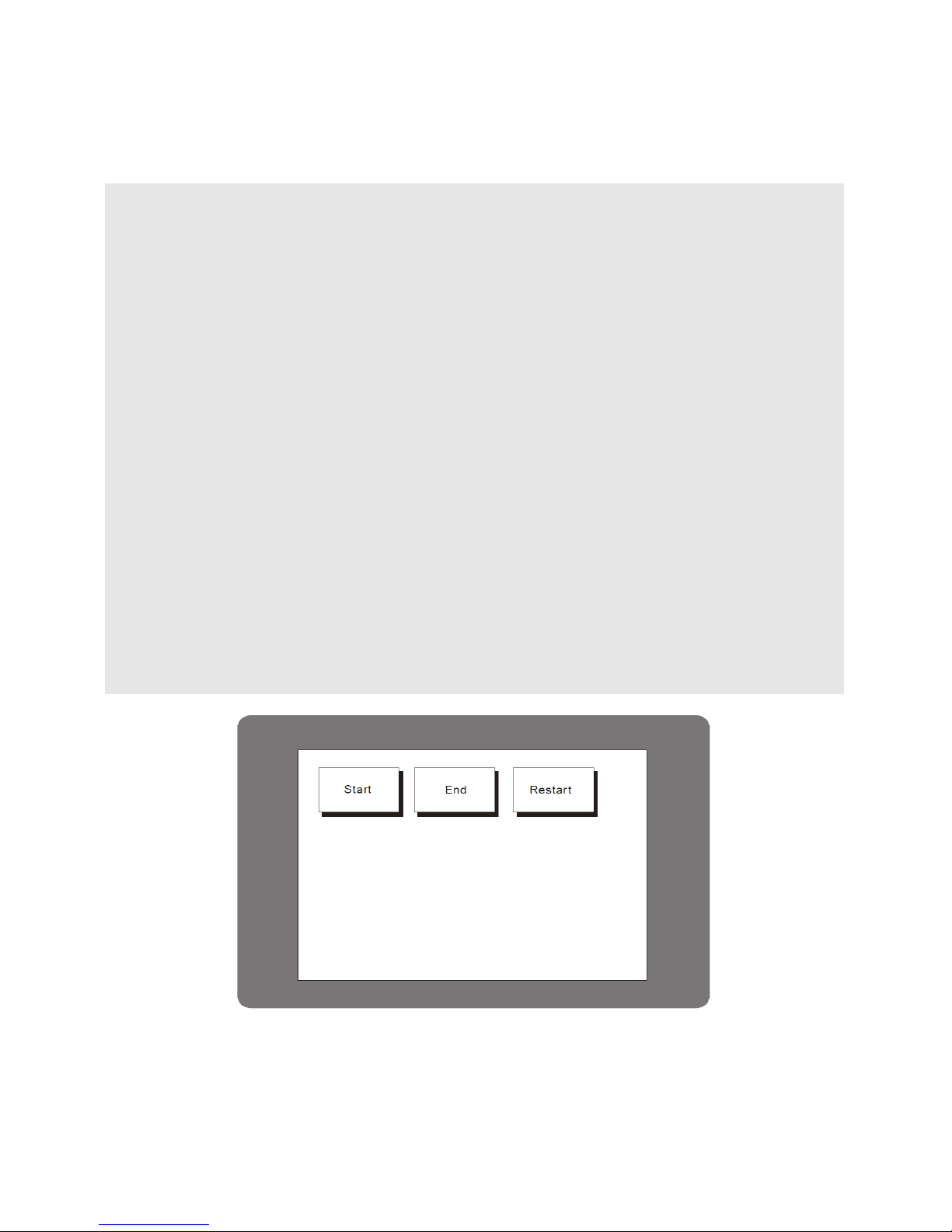
The following program shows how all of the previously mentioned features can be utilized to easily
create an intuitive and responsive user interface. When a button is pressed, its colors will be reversed
for visual feedback, and a "beep" sound will be generated for audio feedback.
'
' Demo for Cutouch
'
#include "CT18XX"
Dim TX1 As Integer, TY1 As Integer
Dim k As Long
CT18contrast 150 ' Adjust this value to change the screen contrast
On Pad Gosub TouchInput
Menuset 0,2,8,16,87,63
Menutitle 0,13,13,"Start"
Menuset 1,2,96,16,176,63
Menutitle 1,13,13,"End"
Menuset 2,2,184,16,264,63
Menutitle 2,13,13,"Restart"
Low 18
Do
Loop
TouhcInput:
TX1 = Sys(10)
TY1 = Sys(11)
Circlefill TX1,TY1,10
If Menucheck(0,TX1,TY1) = 1 Then
Menureverse 0
CT18beep 20 ' Audio feedback
End If
If Menucheck(1,TX1,TY1) = 1 Then
Menureverse 1
CT18beep 20 ' Audio feedback
End If
If Menucheck(2,TX1,TY1) = 1 Then
Menureverse 2
CT18beep 20 ' Audio feedback
End If
Return
Comfile Technology, Inc CT1820 User's Manual 48 Of 93
Page 49
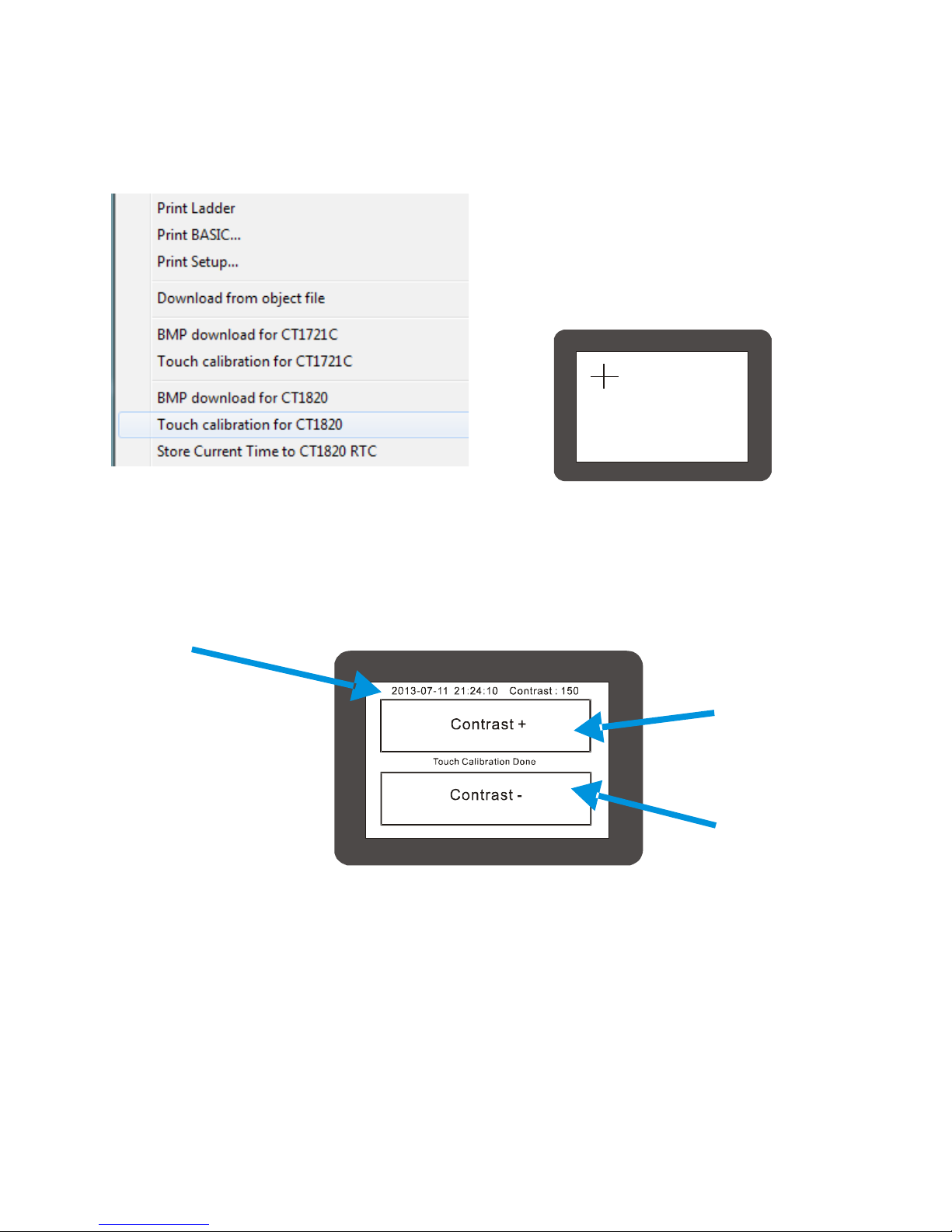
Touch Calibration
In Cubloc Studio select the "Touch calibration
for CT1820" menu option from the "File"
menu to download and execute a program to
calibrate the touchscreen.
The user will be prompted to touch 4 points
on the screen to complete the calibration.
The calibration settings will be stored in the CT1820's EEPROM so the calibration will be retained even if
the CT1820 is powered off.
The PC's current date and time will also be synchronized with the CT1820's RTC.
After the calibration is finished, the screen contrast can be adjusted. The screen contrast values will be
written to EEPROM address &HFFF and can be read at runtime if necessary.
Displays
the
current
date and
time
Increase the
screen
contrast
Decrease
the screen
contrast
Comfile Technology, Inc CT1820 User's Manual 49 Of 93
Page 50

Each CT1820 will have to have its contrast set individually. It can be set at runtime using the CT18Contrast command as
shown below.
CT18Contrast 150
If using the "Touch calibration for the CT1820" menu option in Cubloc Studio, the contrast value can be read and assigned at
runtime as shown below.
CT18Contrast EERead(&HFFF,1)
To ensure the value in the EEPROM represents a usable value use the following code to filter out any values that may be too bright
or too dark.
Dim Cont_value As Byte
Cont_value = EERead(&hfff,1)
If Cont_value < 100 Or Cont_value > 200 Then ' Set and appropriate value if needed
Cont_value = 150
Endif
CT18Contrast Cont_value
Comfile Technology, Inc CT1820 User's Manual 50 Of 93
Page 51
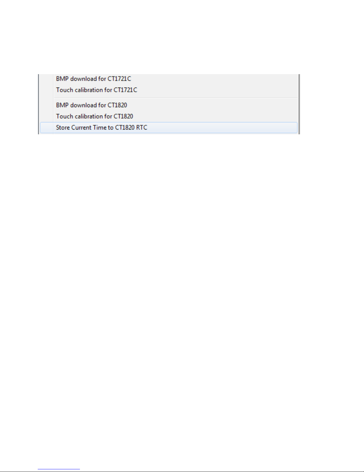
Setting the RTC's Date and Time
In Cubloc Studio's "File" menu, there is a "Store Current Time to CT1820 RTC" menu option. This
feature can be used to set the CT1820's RTC's date and time to that of the PC running Cubloc Studio.
After setting the date and time, the CT1820 will execute a program that can be used to adjust the
screen contrast. The screen contrast will be saved to the EEPROM at address &HFFF and can be read to
set the screen contrast at runtime.
Comfile Technology, Inc CT1820 User's Manual 51 Of 93
Page 52

Chapter 5
ModPort I/O Expansion
Comfile Technology, Inc CT1820 User's Manual 52 Of 93
Page 53
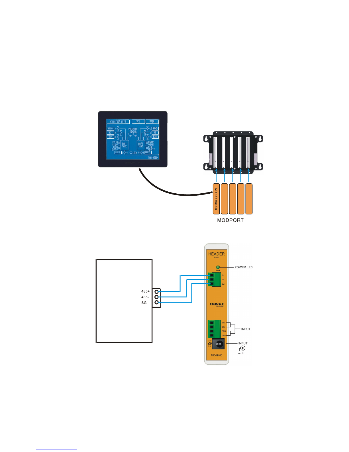
Using the CT2820 with the Modport
The Modport is a modular, RS-485, Modbus field I/O controller from Comfile Technology featuring digital
input and output, analog input, temperature sensing, and a variety of other features. It can be
purchased from http://www.comfiletech.com/modport.aspx.
The CT2820 can be connected to the Modport to expand its I/O capabilities. The CT1820 features a
library of built-in commands to make it simple and easy to communicate with the Modport.
MD- ADIN 4
MD- THRT 4
MD- DAO UT2
MD- DOR L8
Please refer to the illustration below to connect the CT1820 to the Modport.
T1820
C
Comfile Technology, Inc CT1820 User's Manual 53 Of 93
Page 54
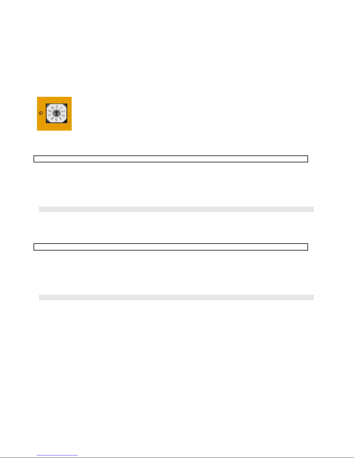
Modport Function Library
This section describes each of the CT1820's built-in Modport functions.
Each Modport module is assigned an ID. The ID is used to distinguish it from other
modules of the same type. The ID can be assigned a number from 0 ~ 9. See the
Modport manual for more information.
MD-DORL8 (8-pin Output Relay)
MPRelay ID, RelayNumber, OnOff
ID: The ID of the module
RelayNumber: Index of the individual relay (0 ~ 7)
OnOff: Whether to turn the relay on or off (on = 1, off = 0)
Command to turn on/off an individual relay on the MD-DORL8 output relay module.
MPRelay 1, 3, 1 ' Turn on module 1, relay 3
MD-DOSO8 (8-pin DC Source Output Module)
MPSource ID, PinNumber, OnOff
ID: The ID of the module
PinNumber: Index of the individual pin (0 ~ 7)
OnOff: Whether to turn the pin on or off (on = 1, off = 0)
Command to turn on/off a pin on the MD-DOSO8 DC source output module.
MPSource 1, 2, 1 ' Turn on module 1, pin 2
Comfile Technology, Inc CT1820 User's Manual 54 Of 93
Page 55

MD-DOSI8 (DC Sink Output Module)
MPSink ID, PinNumber, OnOff
ID: The ID of the module
PinNumber: Index of the individual pin (0 ~ 7)
OnOff: Whether to turn the pin on or off (on = 1, off = 0)
Command to turn on/off a pin on the MD-DOSI8 DC sink output module.
MPSink 1, 2, 1 ' Turn on module 1, pin 2
MD-DIDC8 (8-pin DC Input Module)
Variable = MPIn (ID, PinNumber)
ID : The ID of the module
PinNumber : Index of the individual pin (0 ~ 7)
Reads the state of a pin on the MD-DIDC8 module. The value read is stored in Variable.
A = MPIn(2, 3) ' Read pin 3 of module 2 and store the results in A
Comfile Technology, Inc CT1820 User's Manual 55 Of 93
Page 56

MD-THRT4 (4-channel Resistance Thermometer Module)
Variable = MPThIn (ID, Channel)
ID : The ID of the module
Channel: Channel selection (1 ~ 4)
Reads temperature in °C from a PT100 resistance thermometer. If the module cannot be found 9999 is returned.
If the temperature exceeds the upper threshold, 5555 is returned. If the temperature is below the lower
threshold, -1111 is returned.
The value must be divided by 10 to obtain the actual temperature. For example the value 254 represents a
temperature of 25.4°C. Negative temperatures are indicated with a most significant bit of 1 (Note that this is not
2's complement).
Please see the MD-THRT4's documentation for more information.
A = MPThIn(2, 1) ' Read temperature from module 2, channel 1 and store in A
Comfile Technology, Inc CT1820 User's Manual 56 Of 93
Page 57

MD-ADIN4 (4-Channel analog input module)
Variable = MPADIn (ID, Channel)
ID : The ID of the module
Channel: The number of the channel to read (1~4)
Reads from one of the 4 channels on the MD-ADIN4 module.
If the module cannot be found, 19999 is returned. In 1~5V mode, -11,111 is returned if voltage is less than 1V
and 22,222 is returned if value is greater than 5V. Values falling within the 1~5V rage will return a value between 0
and 10,000 (13.3 bit resolution).
A = MPADIn(2, 3) ' Read from module 2, channel 3 and store value in A
MD-HADIN4 (High-Resolution 4-Channel analog input module)
Variable = MPHADIn ( ID, Channel)
ID: The ID of the module
Channel: The number of the channel to read (1~4)
Reads from one of the 4 channels on the MD-HADIN4 module.
If the module cannot be found, 199,999 is returned. In 1~5V mode, -111,111 is returned if voltage is less than 1V
and 222,222 is returned if value is greater than 5V. Values falling within the 1~5V rage will return a value between
0 and 100,000 (13.3 bit resolution).
A = MPHADIn(2, 3) ' Read from module 2, channel 3 and store value in A
Comfile Technology, Inc CT1820 User's Manual 57 Of 93
Page 58

MD-DAOUT2 (Digital-to-analog voltage output module)
MPDAOutV ID, Channel, OutputValue
ID : The ID of the module
Channel : The channel to output to (1 or 2)
OutputValue : Integer value representing the voltage to output (0~60000)
Outputs a voltage on one of the channels of a MD-DAOUT2 module.
MPDAOutV 1, 2, B ' Outputs voltage B on module 1, channel 2
MD-DAOUT2B (Digital-to-analog current output module)
MPDAOutA ID, Channel, OutputValue
ID : The ID of the module
Channel : The channel to output to (1 or 2)
OutputValue : Integer value representing the current to output (0~60000)
Outputs a current on one of the channels of a MD-DAOUT2 module.
MPDAOutA 1, 2, B ' Outputs current B on module 1, channel 2
Comfile Technology, Inc CT1820 User's Manual 58 Of 93
Page 59
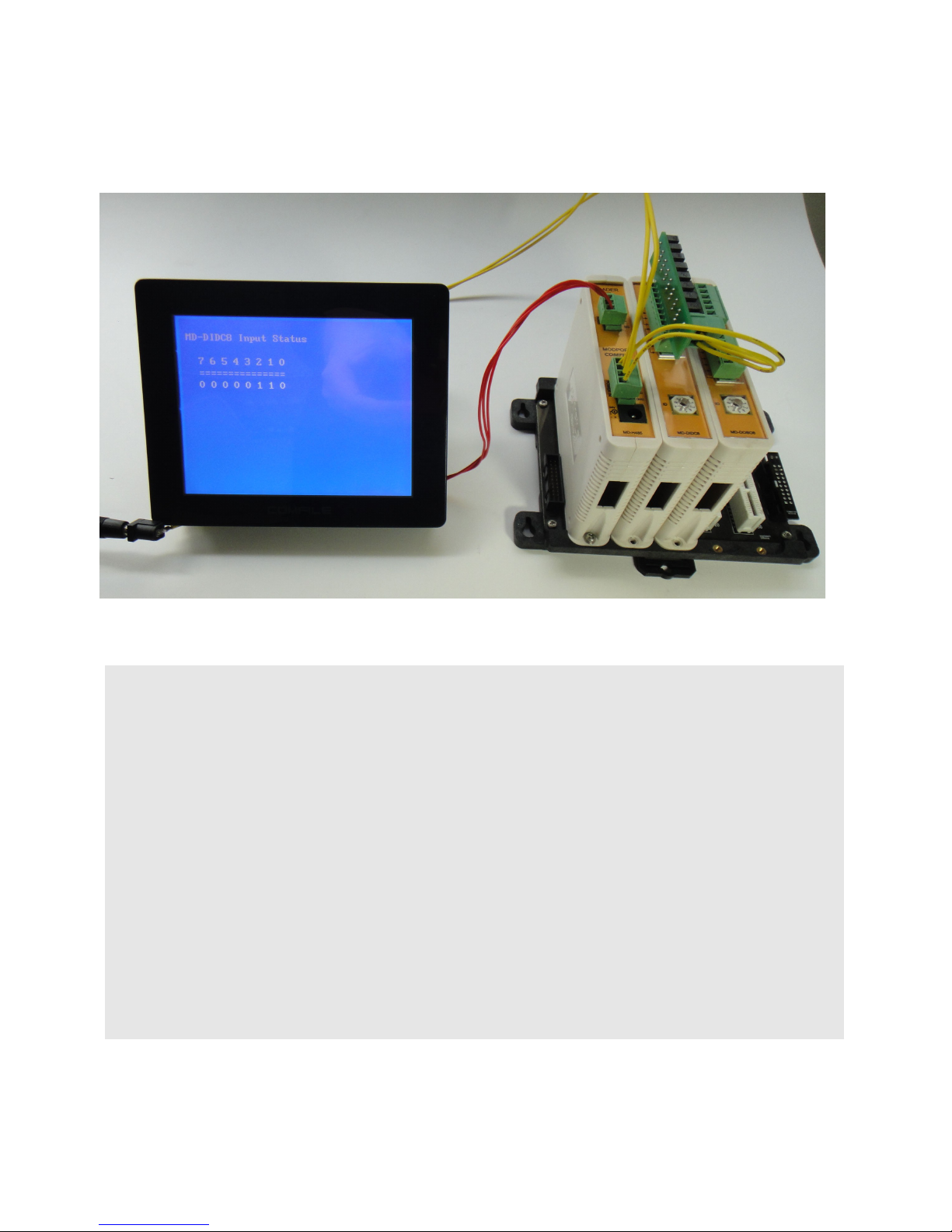
Modport Test Program
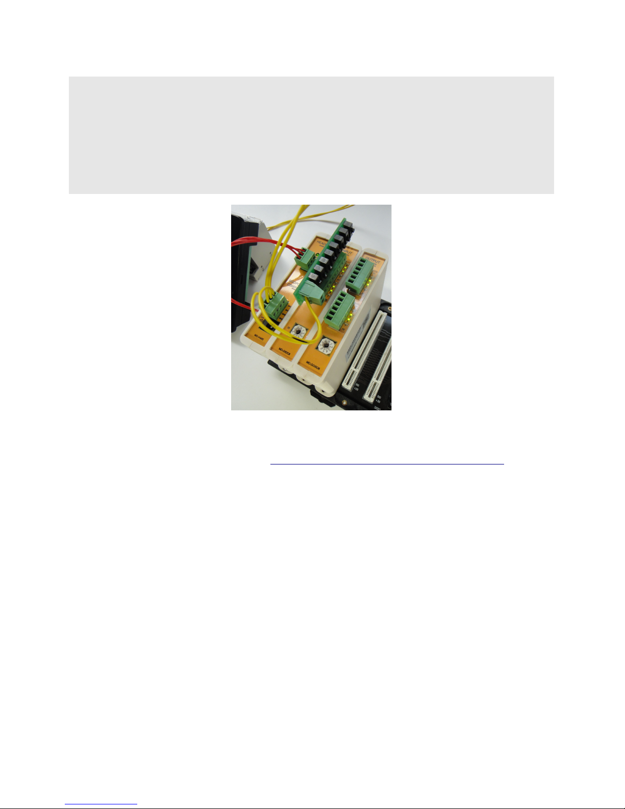
The following program reads the status of 8 inputs on the MD-DIDC8 digital module, and simultaneously
outputs each status to the MD-DOS08 digital output module
#include "CT18XX"
Dim TX1 As Integer
Dim TY1 As Integer
On Pad Gosub TouchOccur
'
'********************* Main Do Loop ************************
'
Locate 1,1
Print "MD-DIDC8 Input Status"
Locate 3,3
Print "7 6 5 4 3 2 1 0"
Locate 3,4
Print "==============="
Do
Locate 2,5
Print hex2 MPin(1,7),hex2 MPin(1,6),hex2 MPin(1,5),hex2 MPin(1,4),hex2 MPin(1,3),hex2
MPin(1,2),hex2 MPin(1,1),hex2 MPin(1,0)
MPsource 2,0,MPin(1,0)
MPsource 2,1,MPin(1,1)
MPsource 2,2,MPin(1,2)
MPsource 2,3,MPin(1,3)
MPsource 2,4,MPin(1,4)
MPsource 2,5,MPin(1,5)
Comfile Technology, Inc CT1820 User's Manual 59 Of 93
Page 60
MPsource 2,6,MPin(1,6)
MPsource 2,7,MPin(1,7)
Wait 500
Loop
TouchOccur:
TX1 = Sys(10)
TY1 = Sys(11)
Pset TX1,TY1
Ct18beep 10
Return
Comfile Technology's input simulator is used in this example to make it easy to toggle and test inputs.
The input simulator can be purchased from http://www.comfiletech.com/inputsimulatoer.aspx.
Comfile Technology, Inc CT1820 User's Manual 60 Of 93
Page 61

Chapter 6
Sample Programs
Comfile Technology, Inc CT1820 User's Manual 61 Of 93
Page 62

Sample 1
This sample program displays an ever-increasing number. This sample is included with the Cubloc
Studio installation.
3 2 41
Simply cut and past this code into Cubloc Studio to give it a try.
#include "CT18XX"
Dim I As Integer
Ct18contrast 150 ' LCD contrast setting
Do
Locate 15, 6
Print DEC5 I
Incr I
Delay 200
Loop
Comfile Technology, Inc CT1820 User's Manual 62 Of 93
Page 63
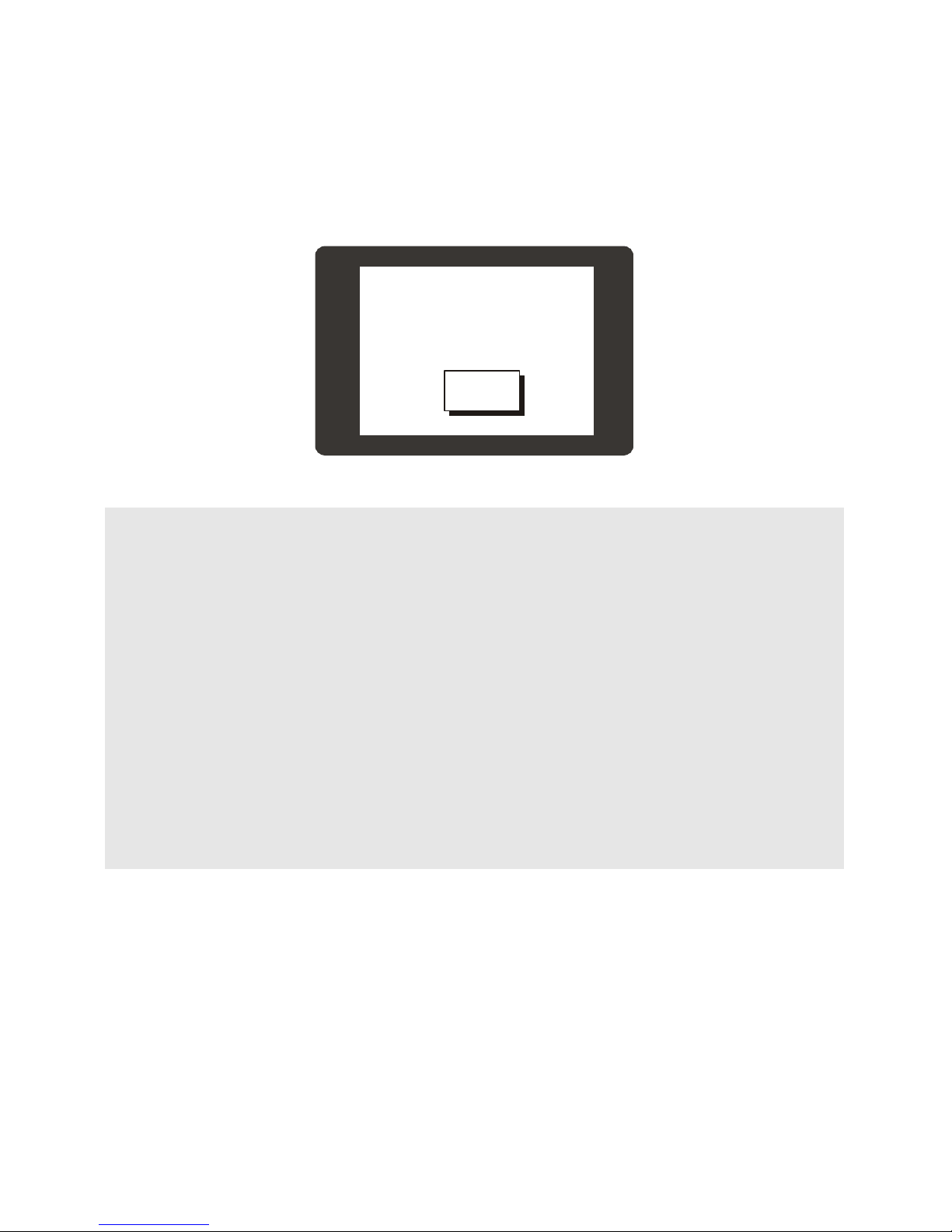
Sample 2
This sample program is similar the previous sample program, but adds a "RESET" button to restart the
count at 0.
32 41
RE SE T
#include "CT18XX"
Dim I As Integer
Ct18contrast 150 ' LCD contrast setting
Dim TX1 As Integer, TY1 As Integer
Contrast 550
On Pad Gosub GETTOUCH
Menuset 0,2,120,155,195,200
Menutitle 0,20,14,"RESET"
Do
Locate 15,6
Print DEC5 I
Incr I
Delay 200
Loop
GETTOUCH:
TX1 = Sys(10)
TY1 = Sys(11)
If Menucheck(0,TX1,TY1) = 1 Then
CT18beep 20 ' Audio feedback
I = 0
End If
Return
Set Pad is used to configure the dedicated kepad/touchpad port. On Pad is used to assign an interrupt
service routine to jump to when a touch event occurs.
Comfile Technology, Inc CT1820 User's Manual 63 Of 93
Page 64

Sample 3
This sample draws a filled circle wherever the screen is touched.
#include "CT18XX"
Dim I As Integer
Dim TX1 As Integer, TY1 As Integer
Ct18contrast 150
On Pad Gosub GETTOUCH
Do
Loop
GETTOUCH:
TX1 = Sys(10)
TY1 = Sys(11)
Circlefill TX1,TY1,2
CT18beep 20 ' Audio feedback
Return
Comfile Technology, Inc CT1820 User's Manual 64 Of 93
Page 65
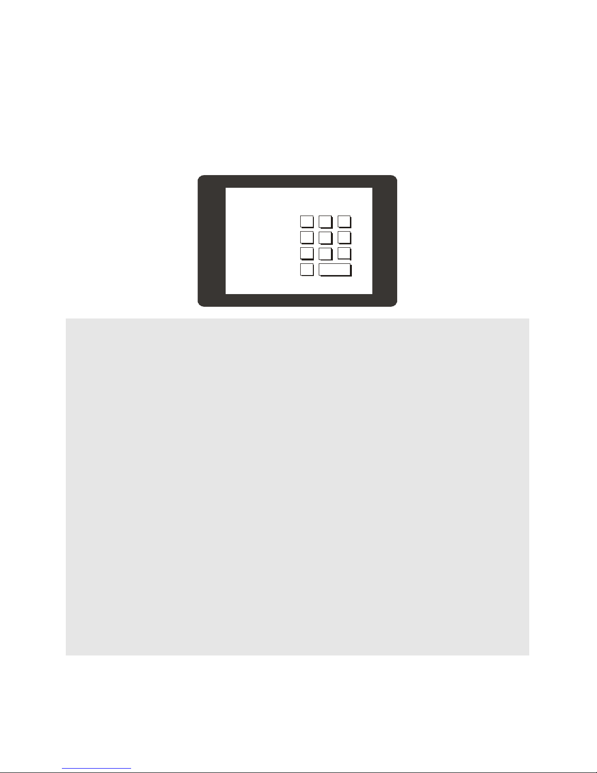
Sample 4: Numeric Input
This sample shows how one can implement a numeric keypad. Enter a number on the keypad, and the
value entered will be displayed on the screen.
1
1234
4
7
0
2
5
8
EN TER
3
6
9
#include "CT18XX"
Dim TX1 As Integer, TY1 As Integer
Dim I As Integer
I=0
Ct18contrast 150
On Pad Gosub GETTOUCH
Menuset 0,2,165,50,195,75
Menutitle 0,11,4,"1"
Menuset 1,2,205,50,235,75
Menutitle 1,11,4,"2"
Menuset 2,2,245,50,275,75
Menutitle 2,11,4,"3"
Menuset 3,2,165,85,195,110
Menutitle 3,11,4,"4"
Menuset 4,2,205,85,235,110
Menutitle 4,11,4,"5"
Menuset 5,2,245,85,275,110
Menutitle 5,11,4,"6"
Menuset 6,2,165,120,195,145
Menutitle 6,11,4,"7"
Menuset 7,2,205,120,235,145
Menutitle 7,11,4,"8"
Menuset 8,2,245,120,275,145
Menutitle 8,11,4,"9"
Menuset 9,2,165,155,195,180
Menutitle 9,11,4,"0"
Menuset 10,2,205,155,275,180
Menutitle 10,17,4,"ENTER"
I =0
Do
Loop
GETTOUCH:
TX1 = Sys(10)
TY1 = Sys(11)
If Menucheck(0,TX1,TY1) = 1 Then
Comfile Technology, Inc CT1820 User's Manual 65 Of 93
Page 66

I = I << 4
I = I + 1
CT18beep 20 ' Audio feedback
Elseif Menucheck(1,TX1,TY1) = 1 Then
I = I << 4
I = I + 2
CT18beep 20
Elseif Menucheck(2,TX1,TY1) = 1 Then
I = I << 4
I = I + 3
CT18beep 20
Elseif Menucheck(3,TX1,TY1) = 1 Then
I = I << 4
I = I + 4
CT18beep 20
Elseif Menucheck(4,TX1,TY1) = 1 Then
I = I << 4
I = I + 5
CT18beep 20
Elseif Menucheck(5,TX1,TY1) = 1 Then
I = I << 4
I = I + 6
CT18beep 20
Elseif Menucheck(6,TX1,TY1) = 1 Then
I = I << 4
I = I + 7
CT18beep 20
Elseif Menucheck(7,TX1,TY1) = 1 Then
I = I << 4
I = I + 8
CT18beep 20
Elseif Menucheck(8,TX1,TY1) = 1 Then
I = I << 4
I = I + 9
CT18beep 20
Elseif Menucheck(9,TX1,TY1) = 1 Then
I = I << 4
CT18beep 20
Elseif Menucheck(10,TX1,TY1) = 1 Then
Locate 3,5
Print Hex4 i
I = 0
CT18beep 20
End If
Locate 3,3
Print HEX4 I
Return
The final result is stored as binary coded decimal (BCD), so the BCD2Bin command is used to convert
the value to binary format.
Comfile Technology, Inc CT1820 User's Manual 66 Of 93
Page 67
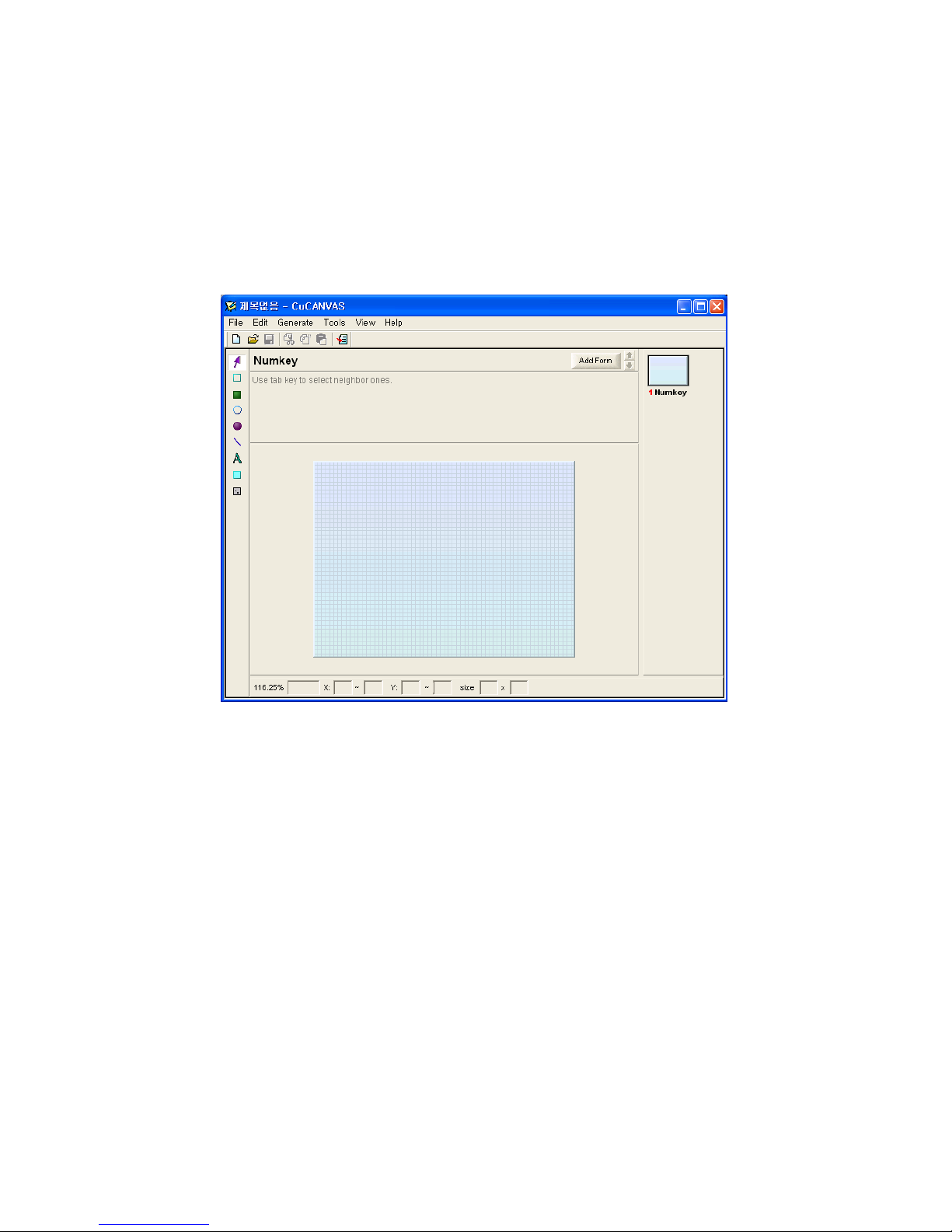
Sample 5: CuCanvas
It can be quite inconvenient to compute coordinates and layout a user interface in code, so Comfile
Technology created the CuCanvas WYSIWYG utility to make it easier for users to layout a user interface
and generate the necessary BASIC code. CuCanvas is a free download from Comfile Technology's
website.
In CuCanvas, click the "Add Form" button to create a new from called "NumKey" as shown below.
Comfile Technology, Inc CT1820 User's Manual 67 Of 93
Page 68
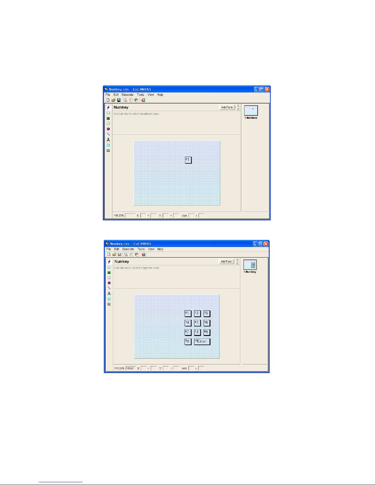
The toolbar on the left can be used to draw boxes, circles, lines, etc.. Click the "Menu for CUTOUCH"
button to add a menu button. After clicking the button, draw the button on the screen.
The menu button index (ID) will be displayed in the top left corner. Enter text in the "Title" textbox to
change the button's caption.
Add additional buttons to create the numpad as shown below.
Comfile Technology, Inc CT1820 User's Manual 68 Of 93
Page 69
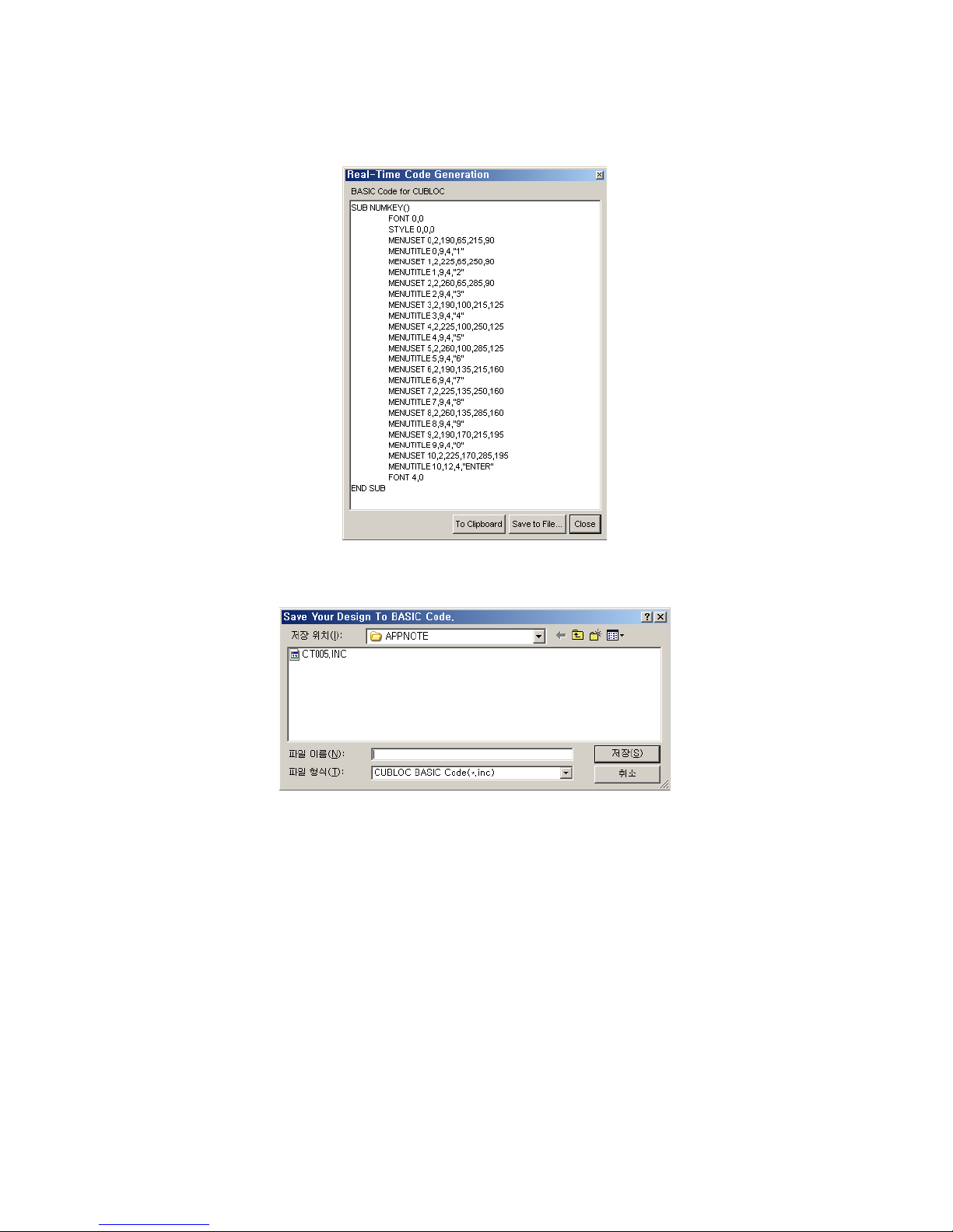
Select the "View/Hide Code" button from the top toolbar to show the generated BASIC code. As shown
below. Click the "To Clipboard" button to copy the code and paste it in "Cubloc Studio".
The code can also be saved as a Cubloc Studio include file by choosing the "Save to File.." button.
Comfile Technology, Inc CT1820 User's Manual 69 Of 93
Page 70

Include files make it easy to change the interface of a program without a lot of cut and paste operations
within the main code.
The following program is exactly same as Sample 4 except an include file is used for the virtual keypad:
#include "CT18XX"
Dim TX1 As Integer, TY1 As Integer
Dim I As Integer
Ct18contrast 150
On Pad Gosub GETTOUCH
NUMKEY ' Calls subroutine in CT005.inc to draw the user interface
I =0
Do
Loop
GETTOUCH:
TX1 = Sys(10)
TY1 = Sys(11)
If Menucheck(0,TX1,TY1) = 1 Then
I = I << 4
I = I + 1
CT18beep 20
Elseif Menucheck(1,TX1,TY1) = 1 Then
I = I << 4
I = I + 2
CT18beep 20
Elseif Menucheck(2,TX1,TY1) = 1 Then
I = I << 4
I = I + 3
CT18beep 20
Elseif Menucheck(3,TX1,TY1) = 1 Then
I = I << 4
I = I + 4
CT18beep 20
Elseif Menucheck(4,TX1,TY1) = 1 Then
I = I << 4
I = I + 5
CT18beep 20
Elseif Menucheck(5,TX1,TY1) = 1 Then
I = I << 4
I = I + 6
CT18beep 20
Elseif Menucheck(6,TX1,TY1) = 1 Then
I = I << 4
I = I + 7
CT18beep 20
Elseif Menucheck(7,TX1,TY1) = 1 Then
I = I << 4
I = I + 8
CT18beep 20
Elseif Menucheck(8,TX1,TY1) = 1 Then
I = I << 4
I = I + 9
CT18beep 20
Elseif Menucheck(9,TX1,TY1) = 1 Then
I = I << 4
CT18beep 20
Elseif Menucheck(10,TX1,TY1) = 1 Then
I = 0
CT18beep 20
End If
Comfile Technology, Inc CT1820 User's Manual 70 Of 93
Page 71

Locate 3,3
Print HEX4 I
Return
End
#INCLUDE "CT005.INC"
We must place the #include directive at the end of the code, as the generated code is in the form of a
subroutine, which must come after the End statement in the main program.
Comfile Technology, Inc CT1820 User's Manual 71 Of 93
Page 72
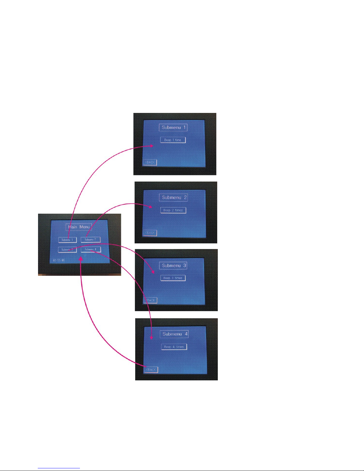
Sample 6: Multi-page Menu Implementation
This sample demonstrates how to set up a paging and menu system.
Switching between screens is quite simple. Maintain a variable that keeps track which screen is currently
being displayed. While switching to a new screen, always update this variable. Use the variable to
determine which set of MenuCheck tests should be run for a particular screen. Subroutines are very
useful for compartmentalizing the code.
The following code can be cut an pasted into Cubloc Studio.
Comfile Technology, Inc CT1820 User's Manual 72 Of 93
Page 73

#include "CT18XX"
Ramclear
Ct18contrast 150
On Pad Gosub ProcessTouch
Dim TX1 As Integer
Dim TY1 As Integer
Dim CurrentScreen As Byte
#define _MAINMENU 0
#define _SUBMENU1 1
#define _SUBMENU2 2
#define _SUBMENU3 3
#define _SUBMENU4 4
MAIN
CurrentScreen = _MAINMENU
Do
If CurrentScreen = _MAINMENU Then
Set Onpad Off
DisplayTime
Set Onpad On
Endif
Delay 250
Loop
ProcessTouch:
TX1 = Sys(10)
TY1 = Sys(11)
Select Case CurrentScreen
Case _MAINMENU
ProcessMainMenu
Case _SUBMENU1
ProcessSubMenu1
Case _SUBMENU2
ProcessSubMenu2
Case _SUBMENU3
ProcessSubMenu3
Case _SUBMENU4
ProcessSubMenu4
End Select
Return
End
Sub ProcessMainMenu()
If Menucheck(0,TX1,TY1) = 1 Then
FlashMenu 0
CurrentScreen = _SUBMENU1
Cls
SUBMENU1
Elseif Menucheck(1,TX1,TY1) = 1 Then
FlashMenu 1
CurrentScreen = _SUBMENU2
Cls
Comfile Technology, Inc CT1820 User's Manual 73 Of 93
Page 74

SUBMENU2
Elseif Menucheck(2,TX1,TY1) = 1 Then
FlashMenu 2
CurrentScreen = _SUBMENU3
Cls
SUBMENU3
Elseif Menucheck(3,TX1,TY1) = 1 Then
FlashMenu 3
CurrentScreen = _SUBMENU4
Cls
SUBMENU4
Endif
End Sub
Sub ProcessSubMenu1()
If Menucheck(0,TX1,TY1) = 1 Then
FlashMenu 0
Beeper 1
Elseif Menucheck(1,TX1,TY1) = 1 Then
FlashMenu 1
CurrentScreen = _MAINMENU
Cls
MAIN
Endif
End Sub
Sub ProcessSubMenu2()
If Menucheck(0,TX1,TY1) = 1 Then
FlashMenu 0
Beeper 2
Elseif Menucheck(1,TX1,TY1) = 1 Then
FlashMenu 1
CurrentScreen = _MAINMENU
Cls
MAIN
Endif
End Sub
Sub ProcessSubMenu3()
If Menucheck(0,TX1,TY1) = 1 Then
FlashMenu 0
Beeper 3
Elseif Menucheck(1,TX1,TY1) = 1 Then
FlashMenu 1
CurrentScreen = _MAINMENU
Cls
MAIN
Endif
End Sub
Sub ProcessSubMenu4()
If Menucheck(0,TX1,TY1) = 1 Then
FlashMenu 0
Beeper 4
Elseif Menucheck(1,TX1,TY1) = 1 Then
FlashMenu 1
CurrentScreen = _MAINMENU
Cls
MAIN
Endif
Comfile Technology, Inc CT1820 User's Manual 74 Of 93
Page 75

End Sub
Sub Beeper(Num As Byte)
Dim i As Byte
For i = 1 To Num
CT18beep 20
Wait 200
Next
End Sub
Sub FlashMenu(Num As Byte)
Menureverse Num
Delay 150
Menureverse Num
End Sub
Sub DisplayTime()
Glocate 16,220
Font 0,0
Dprint
Dp(Bcd2bin(Rtcread(2)),2,1),":",Dp(Bcd2bin(Rtcread(1)),2,1),":",Dp(Bcd2bin(Rtcread(0)),
2,1)
End Sub
Sub MAIN()
Font 6,1
Style 0,0,0
Glocate 96,24
Gprint "Main Menu"
Font 0,1
Menuset 0,2,40,96,144,128
Menutitle 0,20,8,"Submenu 1"
Menuset 1,2,168,96,280,128
Menutitle 1,24,8,"Submenu 2"
Menuset 2,2,40,152,144,184
Menutitle 2,20,8,"Submenu 3"
Menuset 3,2,168,152,280,184
Menutitle 3,24,8,"Submenu 4"
Linestyle 0
Dotsize 0,0
Color 1
Box 80,16,232,56
Font 4,0
End Sub
Sub SUBMENU1()
Font 6,1
Style 0,0,0
Glocate 96,24
Gprint "Submenu 1"
Linestyle 0
Dotsize 0,0
Color 1
Box 80,16,232,56
Font 2,1
Menuset 0,2,88,88,224,120
Menutitle 0,22,8,"Beep 1 time"
Menuset 1,2,0,208,72,239
Menutitle 1,10,7,"<BACK"
Font 4,0
Comfile Technology, Inc CT1820 User's Manual 75 Of 93
Page 76

End Sub
Sub SUBMENU2()
Font 6,1
Style 0,0,0
Glocate 96,24
Gprint "Submenu 2"
Linestyle 0
Dotsize 0,0
Color 1
Box 80,16,232,56
Font 2,1
Menuset 0,2,88,88,224,120
Menutitle 0,16,8,"Beep 2 times"
Menuset 1,2,0,208,72,239
Menutitle 1,10,7,"<BACK"
Font 4,0
End Sub
Sub SUBMENU3()
Font 6,1
Style 0,0,0
Glocate 96,24
Gprint "Submenu 3"
Linestyle 0
Dotsize 0,0
Color 1
Box 80,16,232,56
Font 2,1
Menuset 0,2,88,88,224,120
Menutitle 0,16,8,"Beep 3 times"
Menuset 1,2,0,208,72,239
Menutitle 1,10,7,"<BACK"
Font 4,0
End Sub
Sub SUBMENU4()
Font 6,1
Style 0,0,0
Glocate 96,24
Gprint "Submenu 4"
Linestyle 0
Dotsize 0,0
Color 1
Box 80,16,232,56
Font 2,1
Menuset 0,2,88,88,224,120
Menutitle 0,16,8,"Beep 4 times"
Menuset 1,2,0,208,72,239
Menutitle 1,10,7,"<BACK"
Font 4,0
End Sub
The CurrentScreen variable is used to keep track of the active page being displayed. This variable is
checked in the touch interrupt service routine to determine which set of MenuChecks to perform.
Comfile Technology, Inc CT1820 User's Manual 76 Of 93
Page 77

Sample 7: Contrast Adjustment
This program demonstrates how to adjust the screen contrast at runtime. The screen contrast is stored
in the EEPROM at addres &HFFF.
#include "CT18XX"
Dim CT18_cont_value As Byte
CT18_cont_value = Eeread(&hfff,1)
If CT18_cont_value = &hff Then
CT18_cont_value = 150
Endif
Ct18contrast CT18_cont_value
Box 10,20,310,100
Box 10,140,310,230
Font 5,1
Glocate 120,50
Gprint "Contrast +"
Glocate 120,175
Gprint "Contrast -"
Ct18beep 30
Font 2,0
On Pad Gosub TouchOccur
'
' ********************* Main Loop ************************
'
Do
Locate 0,0
Print "20",Hp(Rtcread(6),2,1),"-",Hp(Rtcread(5),2,1),"-",Hp(Rtcread(4),2,1), "
", Hp(Rtcread(2),2,0),":",Hp(Rtcread(1),2,1),":",Hp(Rtcread(0),2,1)
Locate 24,0
Print "Contrast : ",Dp(CT18_cont_value,3,0)
Wait 1000
Loop
TouchOccur:
_TouchPosx = Sys(10)
_TouchPosy = Sys(11)
If _TouchPosy > 120 Then
CT18_cont_value = CT18_cont_value - 1
Ct18contrast CT18_cont_value
Eewrite &hfff,CT18_cont_value,1
Else
CT18_cont_value = CT18_cont_value + 1
Ct18contrast CT18_cont_value
Eewrite &hfff,CT18_cont_value,1
Endif
Ct18beep 30
Return
End
Comfile Technology, Inc CT1820 User's Manual 77 Of 93
Page 78
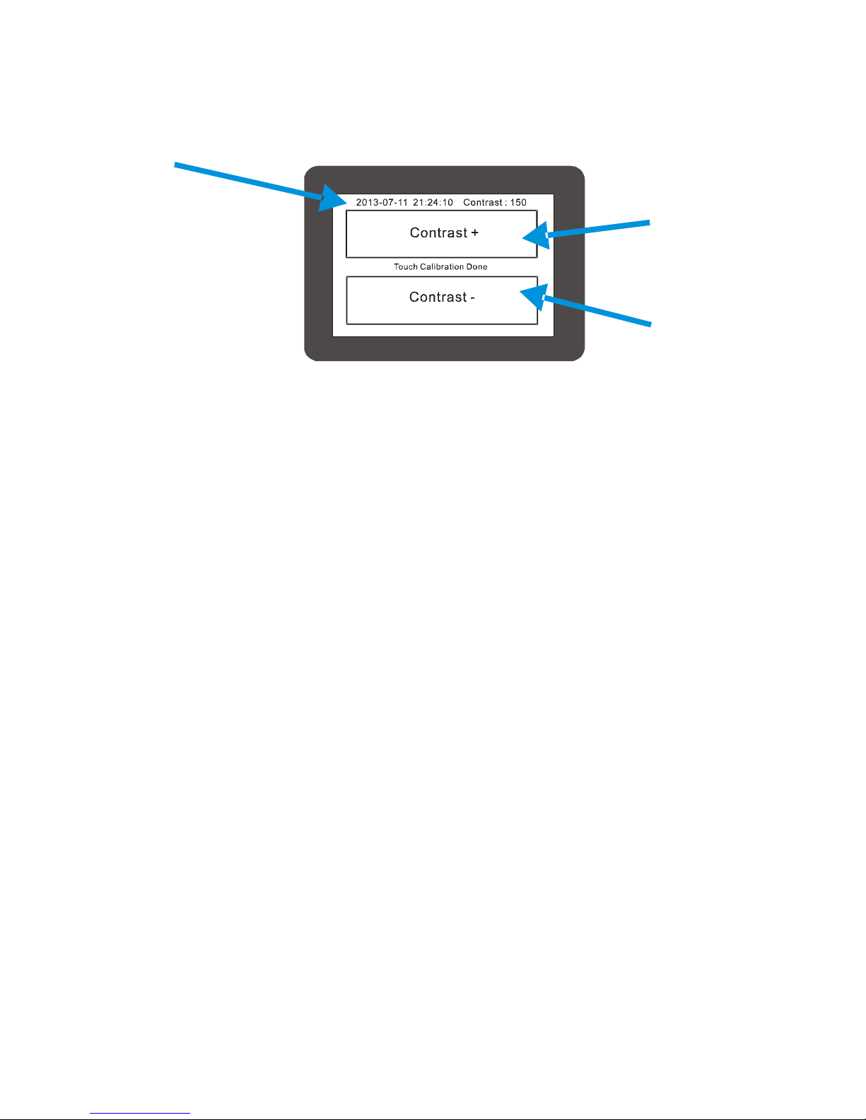
The date and time are displayed on the top of the screen as read from the RTC.
Displays
the
current
date and
time
Increase the
screen
contrast
Decrease
the screen
contrast
Comfile Technology, Inc CT1820 User's Manual 78 Of 93
Page 79
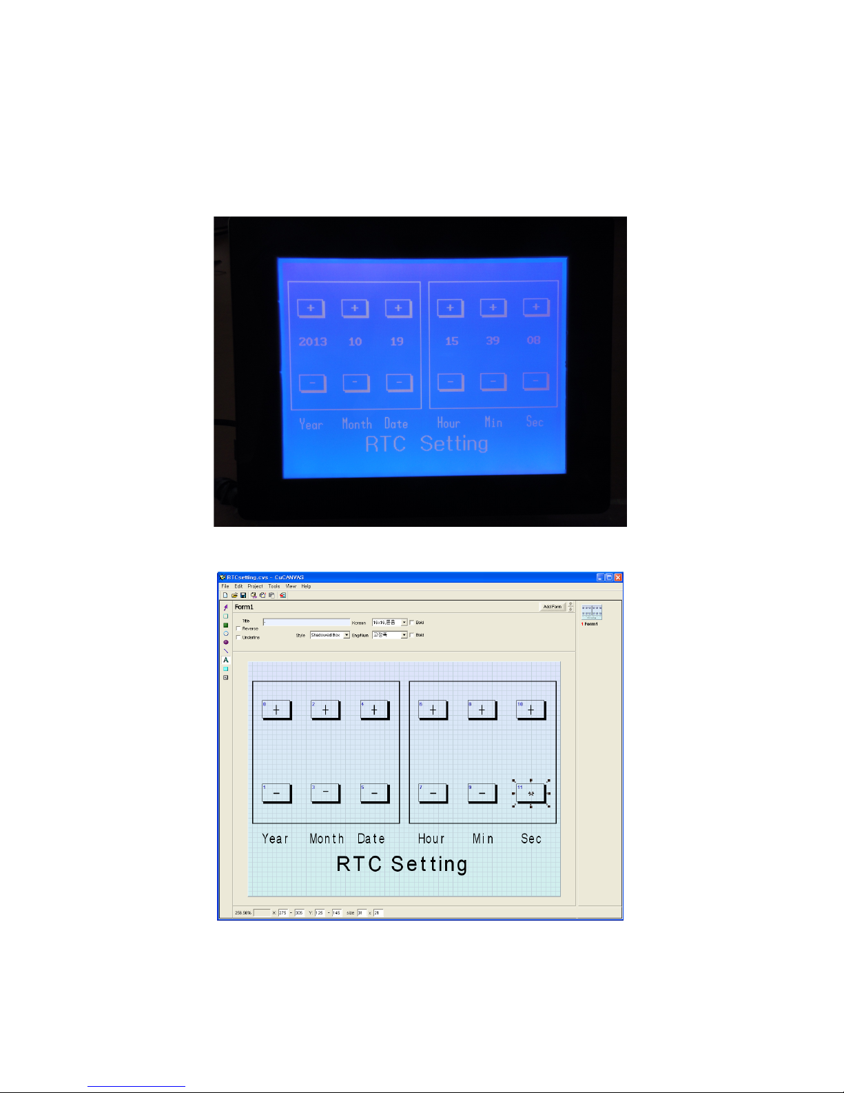
Sample 8: RTC Adjustment
This sample program can be used to adjust the RTC's date and time.
The user interface layout is created with CuCanvas.
Comfile Technology, Inc CT1820 User's Manual 79 Of 93
Page 80

#include "CT18XX"
Dim TX1 As Integer
Dim TY1 As Integer
Dim Va As Integer
Basic_FORM1
On Pad Gosub TouchOccur
'
' ********************* Main Loop ************************
'
Do
Locate 2,5
Print "20",Hp(Rtcread(6),2,1)," ", Hp(Rtcread(5),2,1)," ",
Hp(Rtcread(4),2,1)
Locate 23,5
Print Hp(Rtcread(2),2,1)," ", Hp(Rtcread(1),2,1)," ", Hp(Rtcread(0),2,1)
Wait 1000
Loop
TouchOccur:
TX1 = Sys(10)
TY1 = Sys(11)
If Menucheck(0,TX1,TY1) = 1 Then ' Year
EffectFlash 0
VaIncr 6,99
Elseif Menucheck(1,TX1,TY1) = 1 Then
EffectFlash 1
VaDecr 6,0
Endif
If Menucheck(2,TX1,TY1) = 1 Then ' Month
EffectFlash 2
VaIncr 5,12
Elseif Menucheck(3,TX1,TY1) = 1 Then
EffectFlash 3
VaDecr 5,1
Endif
If Menucheck(4,TX1,TY1) = 1 Then ' Date
EffectFlash 4
VaIncr 4,31
Elseif Menucheck(5,TX1,TY1) = 1 Then
EffectFlash 5
VaDecr 4,1
Endif
If Menucheck(6,TX1,TY1) = 1 Then ' Hour
EffectFlash 6
VaIncr 2,23
Elseif Menucheck(7,TX1,TY1) = 1 Then
EffectFlash 7
VaDecr 2,0
Endif
If Menucheck(8,TX1,TY1) = 1 Then ' Min
EffectFlash 8
VaIncr 1,59
Elseif Menucheck(9,TX1,TY1) = 1 Then
EffectFlash 9
VaDecr 1,0
Endif
If Menucheck(10,TX1,TY1) = 1 Then ' Sec
EffectFlash 10
VaIncr 0,59
Comfile Technology, Inc CT1820 User's Manual 80 Of 93
Page 81

Elseif Menucheck(11,TX1,TY1) = 1 Then
EffectFlash 11
VaDecr 0,0
Endif
Return
End
Sub EffectFlash (IxM As Integer)
Menureverse IxM
Ct18beep 20
Wait 200
Menureverse IxM
End Sub
Sub VaIncr(AddrRTC As Integer, LimitThis As Integer)
Dim Tm As Byte
Dim Dtm As Byte
Tm = Rtcread(AddrRTC)
Dtm = Bcd2bin(Tm)
Incr Dtm
If Dtm > LimitThis Then Decr Dtm
Tm = Bin2bcd(Dtm)
Rtcwrite AddrRTC,Tm
End Sub
Sub VaDecr(AddrRTC As Integer, Limitunder As Integer)
Dim Tm As Byte
Dim Dtm As Byte
Tm = Rtcread(AddrRTC)
Dtm = Bcd2bin(Tm)
If Dtm > Limitunder Then Decr Dtm
Tm = Bin2bcd(Dtm)
Rtcwrite AddrRTC,Tm
End Sub
Sub Basic_FORM1()
Font 2,0
Style 0,0,0
Menuset 0,2,15,40,45,60
Menutitle 0,11,2,"+"
Menuset 1,2,15,125,45,145
Menutitle 1,11,2,"-"
Menuset 2,2,65,40,95,60
Menutitle 2,11,2,"+"
Font 0,0
Menuset 3,2,65,125,95,145
Menutitle 3,11,2,"-"
Font 3,0
Menuset 4,2,115,40,145,60
Menutitle 4,11,2,"+"
Menuset 5,2,115,125,145,145
Menutitle 5,11,2,"-"
Menuset 6,2,175,40,205,60
Menutitle 6,11,2,"+"
Menuset 7,2,175,125,205,145
Menutitle 7,11,2,"-"
Menuset 8,2,225,40,255,60
Comfile Technology, Inc CT1820 User's Manual 81 Of 93
Page 82

Menutitle 8,11,2,"+"
Menuset 9,2,225,125,255,145
Menutitle 9,11,2,"-"
Font 2,0
Menuset 10,2,275,40,305,60
Menutitle 10,11,2,"+"
Font 3,0
Menuset 11,2,275,125,305,145
Menutitle 11,11,2,"-"
Linestyle 0
Dotsize 0,0
Color 1
Box 5,20,155,165
Box 165,20,315,165
Font 0,1
Glocate 15,175
Gprint "Year Month Date "
Glocate 175,175
Gprint "Hour Min Sec"
Font 6,1
Glocate 90,195
Gprint "RTC Setting"
Font 4,0
End Sub
Comfile Technology, Inc CT1820 User's Manual 82 Of 93
Page 83
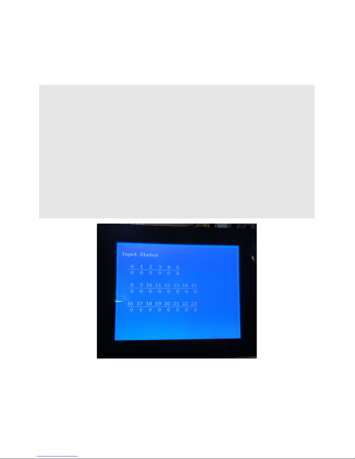
Sample 9: Input Status Monitor
This program displays the state of each digital input.
#include "CT18XX"
Style 0,0,0
Locate 1,1
Print "Input Status"
Style 0,0,1
Locate 3,3
Print " 0 1 2 3 4 5"
Locate 3,6
Print " 8 9 10 11 12 13 14 15"
Locate 3,9
Print "16 17 18 19 20 21 22 23"
Style 0,0,0
Do
Locate 2,4
Print hex3 In(0),hex3 In(1),hex3 In(2),hex3 In(3),hex3 In(4),hex3 In(5)
Locate 2,7
Print hex3 In(8),hex3 In(9),hex3 In(10),hex3 In(11)
Print hex3 In(12),hex3 In(13),hex3 In(14),hex3 In(15)
Locate 2,10
Print hex3 In(16),hex3 In(17),hex3 In(18),hex3 In(19)
Print hex3 In(20),hex3 In(21),hex3 In(22),hex3 In(23)
Wait 500
Loop
Comfile Technology, Inc CT1820 User's Manual 83 Of 93
Page 84

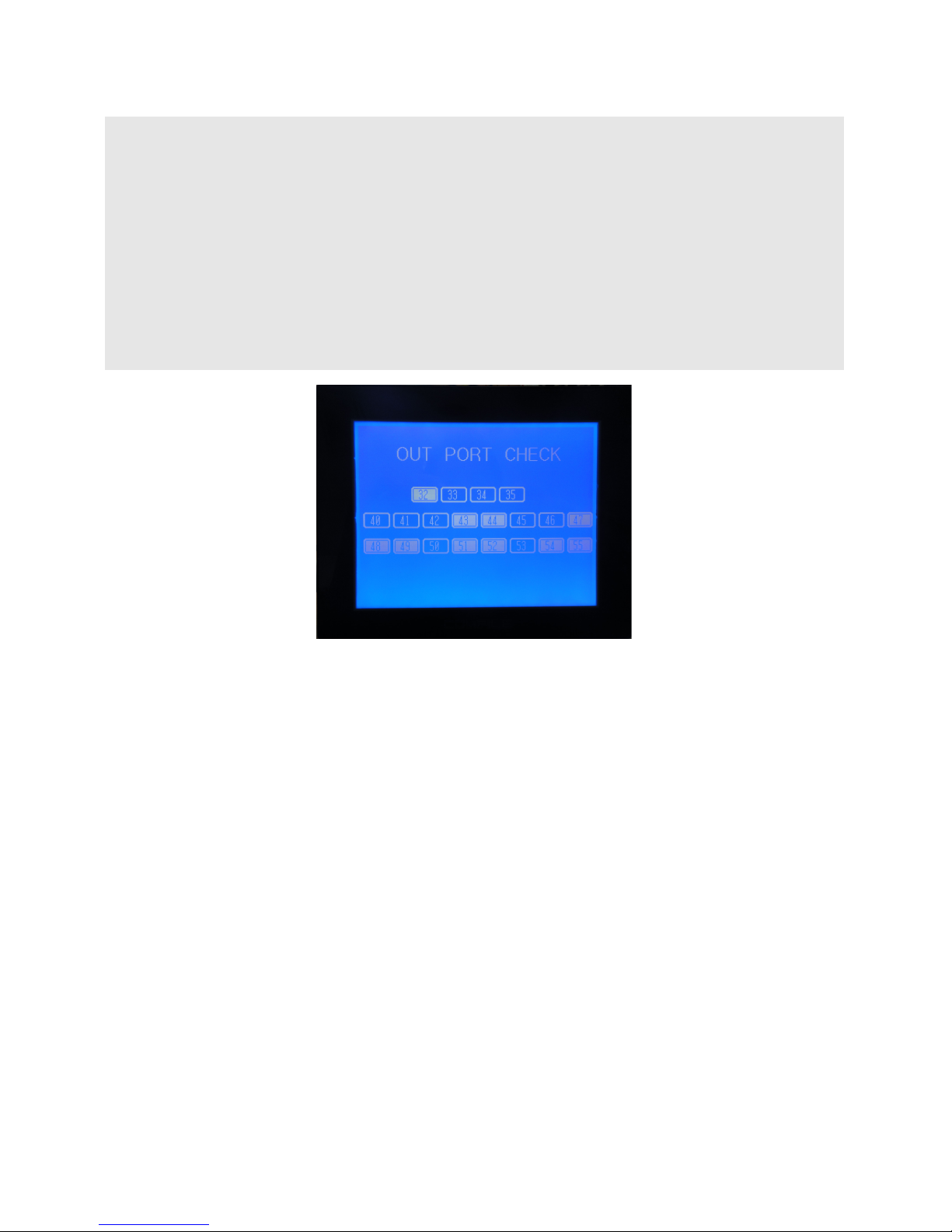
Sample 10: Digital Output Control
This program can be used to control the state of each digital output.
#include "CT18XX"
Dim TX1 As Integer
Dim TY1 As Integer
Dim Ixx As Integer
Basic_FORM1
Byteout 4,0
Byteout 5,0
Byteout 6,0
On Pad Gosub TouchOccur
Do
Loop
TouchOccur:
TX1 = Sys(10)
TY1 = Sys(11)
Ct18beep 10
If Menucheck(0,TX1,TY1) = 1 Then
Menureverse2 0,1
Reverse 32
Elseif Menucheck(1,TX1,TY1) = 1 Then
Menureverse2 1,1
Reverse 33
Elseif Menucheck(2,TX1,TY1) = 1 Then
Menureverse2 2,1
Reverse 34
Elseif Menucheck(3,TX1,TY1) = 1 Then
Menureverse2 3,1
Reverse 35
Elseif Menucheck(4,TX1,TY1) = 1 Then
Menureverse2 4,1
Reverse 40
Elseif Menucheck(5,TX1,TY1) = 1 Then
Menureverse2 5,1
Reverse 41
Elseif Menucheck(6,TX1,TY1) = 1 Then
Menureverse2 6,1
Reverse 42
Elseif Menucheck(7,TX1,TY1) = 1 Then
Menureverse2 7,1
Reverse 43
Elseif Menucheck(8,TX1,TY1) = 1 Then
Menureverse2 8,1
Reverse 44
Elseif Menucheck(9,TX1,TY1) = 1 Then
Menureverse2 9,1
Reverse 45
Elseif Menucheck(10,TX1,TY1) = 1 Then
Menureverse2 10,1
Reverse 46
Elseif Menucheck(11,TX1,TY1) = 1 Then
Menureverse2 11,1
Comfile Technology, Inc CT1820 User's Manual 84 Of 93
Page 85

Reverse 47
Elseif Menucheck(12,TX1,TY1) = 1 Then
Menureverse2 12,1
Reverse 48
Elseif Menucheck(13,TX1,TY1) = 1 Then
Menureverse2 13,1
Reverse 49
Elseif Menucheck(14,TX1,TY1) = 1 Then
Menureverse2 14,1
Reverse 50
Elseif Menucheck(15,TX1,TY1) = 1 Then
Menureverse2 15,1
Reverse 51
Elseif Menucheck(16,TX1,TY1) = 1 Then
Menureverse2 16,1
Reverse 52
Elseif Menucheck(17,TX1,TY1) = 1 Then
Menureverse2 17,1
Reverse 53
Elseif Menucheck(18,TX1,TY1) = 1 Then
Menureverse2 18,1
Reverse 54
Elseif Menucheck(19,TX1,TY1) = 1 Then
Menureverse2 19,1
Reverse 55
Endif
Return
End
Sub Basic_FORM1()
Font 0,0
Style 0,0,0
Menuset2 0,1,70,80,105,100
Menutitle 0,10,4,"32"
Menuset2 1,1,110,80,145,100
Menutitle 1,10,4,"33"
Menuset2 2,1,150,80,185,100
Menutitle 2,10,4,"34"
Menuset2 3,1,190,80,225,100
Menutitle 3,10,4,"35"
Menuset2 4,1,5,115,40,135
Menutitle 4,10,4,"40"
Menuset2 5,1,45,115,80,135
Menutitle 5,10,4,"41"
Menuset2 6,1,85,115,120,135
Menutitle 6,10,4,"42"
Menuset2 7,1,125,115,160,135
Menutitle 7,10,4,"43"
Menuset2 8,1,165,115,200,135
Menutitle 8,10,4,"44"
Menuset2 9,1,205,115,240,135
Menutitle 9,10,4,"45"
Menuset2 10,1,245,115,280,135
Menutitle 10,10,4,"46"
Menuset2 11,1,285,115,319,135
Menutitle 11,9,4,"47"
Menuset2 12,1,5,150,40,170
Menutitle 12,10,4,"48"
Menuset2 13,1,45,150,80,170
Menutitle 13,10,4,"49"
Comfile Technology, Inc CT1820 User's Manual 85 Of 93
Page 86
Menuset2 14,1,85,150,120,170
Menutitle 14,10,4,"50"
Menuset2 15,1,125,150,160,170
Menutitle 15,10,4,"51"
Menuset2 16,1,165,150,200,170
Menutitle 16,10,4,"52"
Menuset2 17,1,205,150,240,170
Menutitle 17,10,4,"53"
Menuset2 18,1,245,150,280,170
Menutitle 18,10,4,"54"
Menuset2 19,1,285,150,319,170
Menutitle 19,9,4,"55"
Font 6,1
Glocate 50,25
Gprint "OUT PORT CHECK"
Font 4,0
End Sub
Comfile Technology, Inc CT1820 User's Manual 86 Of 93
Page 87

Chapter 7
Panel Mounting
Comfile Technology, Inc CT1820 User's Manual 87 Of 93
Page 88

Dimensions
Comfile Technology, Inc CT1820 User's Manual 88 Of 93
Page 89
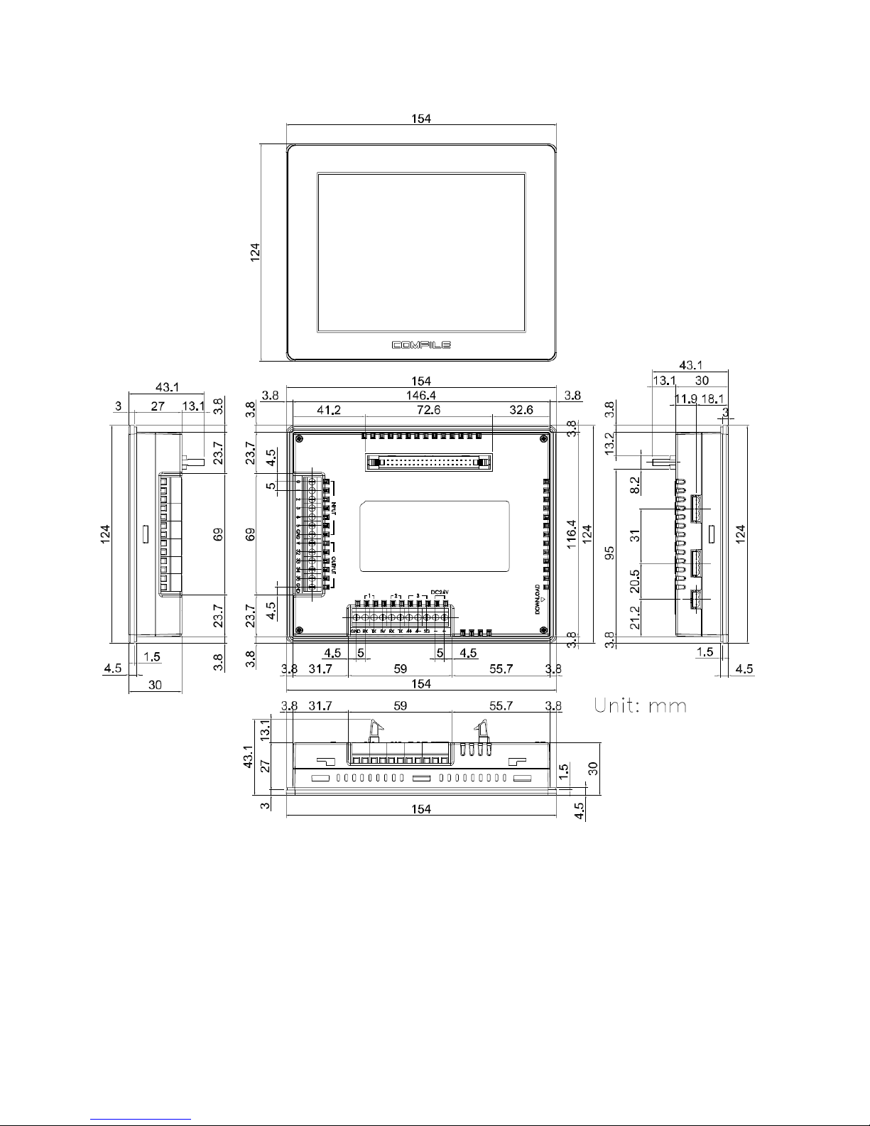
Comfile Technology, Inc CT1820 User's Manual 89 Of 93
Page 90
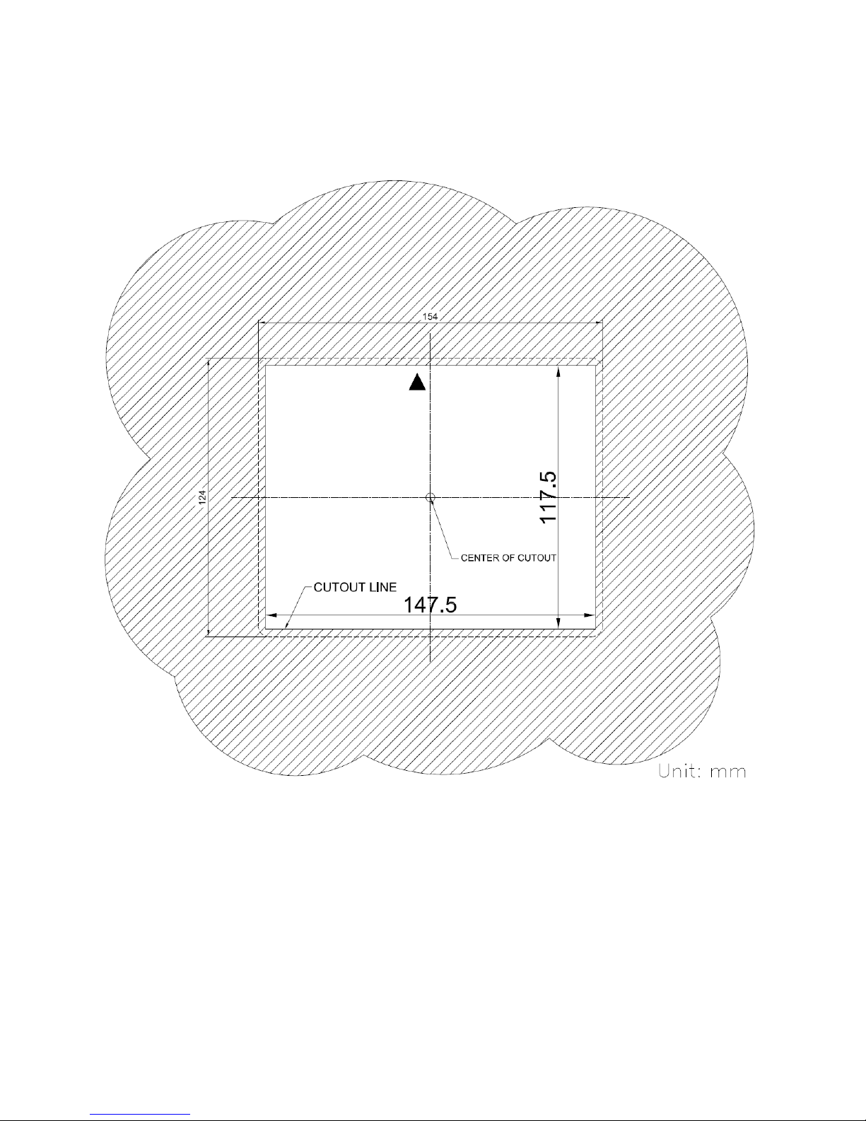
Panel Cutout
Comfile Technology, Inc CT1820 User's Manual 90 Of 93
Page 91
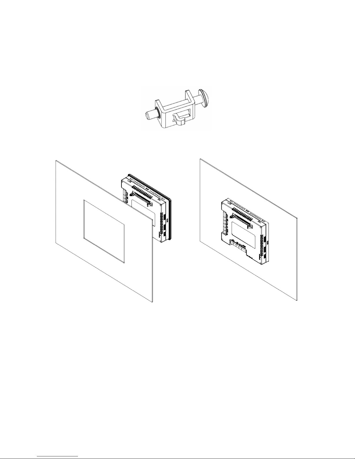
Panel Mounting Procedure
Panel mounting brackets and matching bolts are included with each purchase (upper/lower 2ea.)
(Preparation: Insert the bolt into the mounting bracket as shown in the image below
1. Insert the unit into a properly prepared panel cutout per the previously described panel cutout
dimensions. (Panel thickness can be between 1 and 6 mm.)
Comfile Technology, Inc CT1820 User's Manual 91 Of 93
Page 92
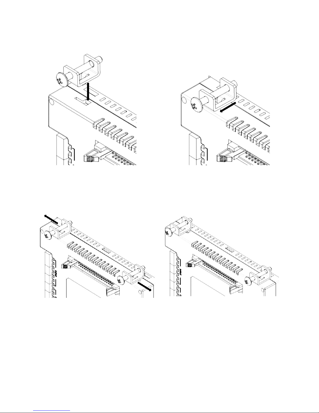
2. Insert the mounting brackets into the groove on the side of the unit, pull the bracket towards
the rear of the unit.
3. Slide the bracket laterally to secure in place.
Comfile Technology, Inc CT1820 User's Manual 92 Of 93
Page 93
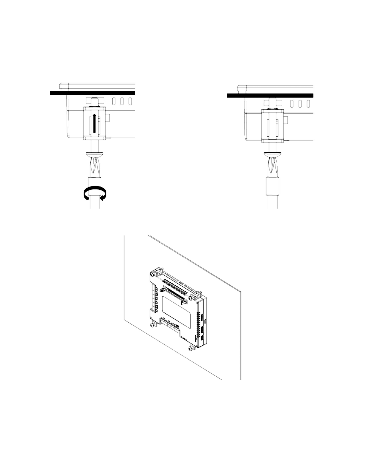
4. Tighten the bolts to secure the unit to the panel.
(Caution: Be careful not to tighten the bolts excessively to avoid damaging to the
unit and/or the panel)
5. Repeat steps 2~4 for each remaining mounting bracket.
- A look at the CT1820 after properly mounted –
Comfile Technology, Inc CT1820 User's Manual 93 Of 93
 Loading...