


www.cometsystem.com
Instruction Manual
T3111
T3111L
T3111P
T3111Ex
Programmable transmitter of temperature, relative humidity
and other calculated humidity values with external probe
and 4 - 20 mA outputs

© Copyright: COMET System, Ltd.
It is prohibited to copy and make any changes in this manual, without explicit
agreement of company COMET System, Ltd. All rights reserved.
COMET System, Ltd. makes constant development and improvement of their
products. Manufacturer reserves the right to make technical changes to the
device without previous notice. Misprints reserved.
Manufacturer is not responsible for damages caused by using the device in
conflict with this manual.
To damages caused by using the device in conflict with this manual can not
be provide free repairs during the warranty period.
Read carefully instruction manual before the first device connection.
2 IE-SNC-T3111-13

Table of contents
GENERAL DESCRIPTION ......................................................................... 4
T3111EX TRANSMITTER .......................................................................... 5
FACTORY SETTINGS ................................ ............................................... 6
DEVICE INSTALLATION ........................................................................... 7
INFO MODE ............................................................................................... 8
MODIFICATION OF DEVICE ADJUSTMENT ............................................ 9
ERROR STATES OF THE DEVICE ......................................................... 10
TECHNICAL SUPPORT AND SERVICE .................................................. 11
TECHNICAL DATA ................................................................ .................. 12
MEASURED VALUES ............................................................................. 12
CALCULATED HUMIDITY VALUES ....................................................... 13
GENERAL ............................................................................................... 14
OPERATING CONDITIONS ................................................................... 16
END OF OPERATION ............................................................................ 16
DIMENSIONS.......................................................................................... 17
TYPICAL APPLICATION WIRING .......................................................... 19
APPENDIX A ........................................................................................... 21
IE-SNC-T3111-13 3

General description
The transmitters T3111 are designed for measurement of ambient
temperature and relative humidity of air without aggressive substances.
Measured values are converted to other humidity interpretation: dew point
temperature, absolute humidity, specific humidity, mixing ratio and specific
enthalpy. The transmitters are equipped with an external humidity and
temperature probe on a cable.
Measured and computed values are displayed on a two-line LCD display.
The first line displays temperature (ºC / ºF). Value displayed on the second
line is selectable among relative humidity and computed value. It is also
possible to display both readings with cyclic overwriting (4 seconds interval)
or to switch off the LCD display at all.
The transmitter communicates by means two galvanically separated current
loop 4-20mA. Each loop has two-wire connection and each loop requires
power from evaluation device. It is always necessary to connect loop I1
which is designed for supplying of measuring part of the device. Using the
configuration software can be assigned to each current loop any measured
or computed value.
All transmitter setting is performed by means of the PC connected via the
optional SP003 communication cable (not included in delivery). Using
TSensor software (see www.cometsystem.com) you can assign to each
output any measured or computed value and to set its measuring range. It is
also possible to assign both outputs to the same value (with the same range),
if two evaluation devices are necessary to connect. The program supports
make the adjustment of the device too. This procedure is described at file
„Calibration manual.pdf“ which is installed commonly with the software.
Device versions:
T3111 transmitter with cable gland for output cable connection
T3111L device version with watertight male connector instead of a
cable gland for easy connection/disconnection of the output
cable (protection IP67)
T3111P transmitter for measuring the moisture of compressed air with
pressure up to 25 bar
T3111Ex intrinsically safe transmitter for use in potentially explosive
environments
T3111Z this marking is intended for a non-standard versions of the
transmitters. Description is not included in this manual.
4 IE-SNC-T3111-13

T3111Ex transmitter
Transmitter T3111Ex is designed and certified for use in hazardous areas.
In compliance with European Directive 2014/34/EU (ATEX) the T3111Ex
transmitter conforms to European Standards EN 60079-0:2018 and
EN 60079-11:2012.
Transmitter is suitable for use in potentially explosive atmospheres
(Apparatus Groups llC) in applications requiring devices category 3G.
Type Examination Certificate number FTZÚ 13 ATEX 0189X is available at
www.cometsystem.com.
IE-SNC-T3111-13 5

Factory settings
If special setting was not required in the order device is set from the
manufacturer to the following parameters:
value at output I1: relative humidity
range 4-20 mA corresponds 0 to 100 %RH
value at output I2: temperature
range 4-20 mA corresponds -30 to +105 ºC
display: switched ON
temperature unit: °C
value displayed at line 2: relative humidity
6 IE-SNC-T3111-13

Warning
Device installation
The housing with electronics is designed for wall mounting with two screws
or bolts. The mounting position of the housing with electronics and of the
probe is arbitrary. To measure temperature and humidity of compressed air
(T3111P) is suitable to use the flow chamber SH-PP (see Appendix A).
The connecting terminals are accessible after unscrewing the four screws in
the corners of the case and removing the lid. Pass the connecting cable
through released gland and connect the wires to terminals (see “Typical
application wiring”). Tighten the gland and screw the lid (check the integrity
of the seal). The female connector for connecting T3111L transmitter
connect according to diagram at “Typical application wiring”.
For device connection it is recommended to use a shielded cable with a
maximum length of 1200m. External diameter of the cable for T3111, T3111P
and T3111Ex connection is 4 to 8 mm. For T3311L connection use cable
with respect to female connector parameters (do not connect shielding at
connector side). When selecting the type of a cable for T3111Ex connection
and when choosing a location for T3111Ex mounting it is necessary to
observe the conditions for safe installation in potentially explosive
environments. The cables should be located as far as possible from potential
interference sources.
It is not recommended to use the device for long time under condensation
conditions or water aerosol conditions. It could be the cause of water steam
condensation inside the sensor’s cover with a consequential increase of
response time to humidity changes. It can cause sensor damage too. If this
effect may occur, it is necessary to use the probe at operation position with
sensor cover downwards.
Devices don´t require special operation and maintenance. It is recommend
to keep clean sensor cover and periodically to verify the accuracy of
measurement.
Installation, commissioning and maintenance may only be carried out by
personnel with qualification by applicable regulations and standards.
Ambient temperature of the housing with electronics of T3111Ex
transmitter is not allowed exceed 60 ºC.
Don´t connect transmitter while power supply voltage is on.
Under certain extreme circumstances, the plastic enclosure of T3111Ex
transmitter may store an ignition-capable level of electrostatic charge.
The device shall not be installed in a location where the external
conditions are conducive to the build-up of electrostatic charge. The
equipment shall only be cleaned with a damp cloth.
IE-SNC-T3111-13 7

Warning
Info mode
Several settings of installed transmitter are possible to verify without a use
of the computer. It is necessary to connect at least power of current loop I1.
Unscrew the transmitter lid and shortly press button between display and
interconnection terminals by means of a tool (e.g. screwdriver).
The LCD display shows the type of value assigned
to 1. output (here „%RH“ = relative humidity and „1“
= loop I1). Upper line displays value of the current
corresponding to measured value on the lower line
(here 4 mA corresponds to 0 %RH).
Press button again to get value for upper point of
the 1. output (here „%RH“ = relative humidity and 1“
= loop 1). Upper line displays value of the current
corresponding to measured value on the lower line
(here 20 mA corresponds to 100 %RH).
After next press of the button LCD display shows
the type of value assigned to 2. output (here „ºC“ =
temperature and „2“= loop I2). Upper line displays
value of the current corresponding to measured
value on the lower line (here 4 mA corresponds to 30 ºC).
Press button again to get value for upper point of
the 2. output (here „ºC“ = temperature and „2“ =
loop 2). Upper line displays value of the current
corresponding to measured value on the lower line
(here 20 mA corresponds to 80 ºC).
Press button again to end info mode and display actual measured values.
During info mode no measurement and no output current generation
proceed. The transmitter stays at info mode 15 s, and then automatically
goes back to measuring cycle.
The verifying of settings of the T3111Ex transmitter is permitted only in
non-hazardous area.
8 IE-SNC-T3111-13

Warning
Modification of device adjustment
Device adjustment is performed by means of the optional SP003
communication cable, connected to USB port of the PC. It is necessary to
have installed configuration program Tsensor on the PC (program is free to
download at www.cometsystem.com). During installation please take care
about installation of driver for USB communication cable.
unscrew four screws of the device lid and remove the lid. If device is
already installed to measuring system, disconnect wires from terminals
connect SP003 communication cable to the
PC. Installed USB driver detect connected
cable and create virtual COM port inside the
PC
run installed Tsensor program and continue
in accordance with his instructions
when new setting is saved and finished,
disconnect the cable from the device, connect wires into its terminals and
place the lid back to the device
Modification of adjustment of the T3111Ex transmitter using a cable
SP003 is permitted only in non-hazardous area.
IE-SNC-T3111-13 9

Error states of the device
Device continuously checks its state during operation. In case error is found
LCD displays corresponding error code:
Error 0 - first line displays „Err0“ (output current value is < 3.8 mA). Check
sum error of stored setting inside device’s memory. This error
appears if incorrect writing procedure to device’s memory occurred
or if damage of calibration data appeared. At this state device does
not measure and calculated values. It is a serious error, contact
distributor of the device to fix.
Error 1 - there is a reading „Err1“ on LCD display (output current value is
> 22 mA). Measured or computed value is higher than upper limit.
This state appears in case of:
measured temperature is higher than approximately 600 °C
(i.e. high non-measurable resistance of temperature sensor,
probably opened circuit)
relative humidity value is higher than 100 %, i.e. damaged
humidity sensor, or humidity calculation of humidity is not
possible (due to error during temperature measurement)
calculation of the computed value is not possible (error during
measurement of temperature or relative humidity or value is
over range)
Error 2 - there is a reading „Err2“ on LCD display (output value is < 3.8 mA).
Measured or computed value is below lower limit of allowed full
scale range. This state appears in case of:
measured temperature is lower than approximately -210 °C (i.e.
low resistance of temperature sensor, probably short circuit).
relative humidity value is lower than 0 %, i.e. damaged sensor
for measurement of relative humidity, or calculation of relative
humidity is not possible (due to error during temperature
measurement)
calculation of the computed value is not possible (error during
measurement of temperature or relative humidity)
Error 3 - there is a reading „Err3“ on LCD display upper line. Error of internal
A/D converter appeared (converter does not respond, probably
damage of A/D converter). No measurement and calculations of
values are proceeded. It is a serious error, contact distributor of
the instrument.
10 IE-SNC-T3111-13

Technical support and service
Technical support and service is provided by distributor. For contact see
warranty certificate. You can use discussion forum at web address
www.forum.cometsystem.cz.
IE-SNC-T3111-13 11

Technical data
Measured values
Temperature:
Accuracy: ±0.4 °C
Measuring range: 0 to +105 °C
Resolution: 0.1 °C
Response time: t90 < 6 min T3111
t90 < 6 min T3111L
t90 < 6 min T3111Ex
t90 < 16 min T3111P
(temperature step 20 ºC)
Relative humidity:
Accuracy: ± 2.5 %RH from 5 to 95 %RH at 23 °C
Measuring range: 0 to 100 %RH
Resolution: 0.1 %RH
Response time: t90 < 30 s (humidity step 65 %RH, constant
Accuracy data are valid for values displayed on LCD display. For accuracy
of analog outputs are valid this data in case, when the output range is set
within the range of measurement.
Relative humidity and temperature restriction:
temperature)
12 IE-SNC-T3111-13

Calculated humidity values
Dew point temperature::
Accuracy: ±1.5°C at ambient temperature T < 25 °C and
RH > 30 %, for more details see graphs
Measuring range: -60 to +80 ºC
Absolute humidity:
Accuracy: ±1.5 g/m3 at ambient temperature T < 25 °C,
for more details see graph
Measuring range: 0 to 400 g/m3
IE-SNC-T3111-13 13

Specific humidity
This value depends on atmospheric pressure. Pressure for quantities
calculation is stored in device memory. Default value is 1013hPa and can
be changed by software.
Accuracy: ±2 g/kg at ambient temperature T < 35 °C
Measuring range: 0 to 550 g/kg
Mixing ratio
This value depends on atmospheric pressure. Pressure for quantities
calculation is stored in device memory. Default value is 1013hPa and can
be changed by software.
Accuracy: ±2 g/kg at ambient temperature T < 35 °C
Measuring range: 0 to 995 g/kg
Specific enthalpy
This value depends on atmospheric pressure. Pressure for quantities
calculation is stored in device memory. Default value is 1013hPa and can
be changed by software.
Accuracy: ±4 kJ/kg at ambient temperature T < 35 °C
Measuring range: 0 to 995 kJ/kg
General
The values computed from ambient temperature and relative humidity
including their accuracy you can exactly determine by the program
Conversions. It is free to download at www.cometsystem.com.
Power supply voltage:
9 to 30 Vdc
Current output in case of error:
< 3.8 mA or > 22 mA
Recommended calibration interval:
1 year (relative humidity 1 year, temperature 2 years)
Protection:
housing with electronics IP65, sensors are located in cover with
IP40 protection
14 IE-SNC-T3111-13

Mechanical connection of probe T3111P:
G1/2 with O-ring
Storage temperature range:
-30 to +80 °C
Storage relative humidity range:
5 to 95 %RH (no condensation)
Certification of T3111Ex transmitter:
Certificate: FTZÚ 13 ATEX 0189X
Marking: ll 3G Ex ic llC T6 Gc
Compliance with standards: EN 60079-0:2018 and EN 60079-11:2012
Intrinsically safe parameters of current loops I1 and I2:
Ui = 30 V, Ii = 100 mA, Io = 22 mA, Ci ~ 0, Li ~ 0
Special condition for safe use (sign “X”): Under certain extreme
circumstances, the plastic enclosure may store an
ignition-capable level of electrostatic charge. The
device shall not be installed in a location where the
external conditions are conducive to the build-up of
electrostatic charge. The equipment shall only be
cleaned with a damp cloth.
Electromagnetic compatibility:
EN 61326-1
Weight: approximately
T3111, T3111L, T3111Ex probe 1m 210 g
T3111, T3111L, T3111Ex probe 2m 250 g
T3111, T3111L, T3111Ex probe 4m 330 g
T3111P probe 1m 260 g
T3111P probe 2m 300 g
T3111P probe 4m 380 g
Housing material:
ABS
Material of the probe T3111P:
duralumin with the black eloxal surface finish
IE-SNC-T3111-13 15

Operating conditions
Temperature operating range of the housing with electronics:
-30 to +80 ºC T3111
-30 to +80 ºC T3111L
-30 to +80 ºC T3111L
Ambient temperature range of the housing with electronics:
-30 to +60 ºC T3111Ex
Temperature operating range of the probe:
-30 to +105 ºC
Relative humidity operating range:
0 to 100 %RH (no condensation)
Operating pressure range of the probe T3111P:
up to 25 bar
Air flow velocity (T3111P probe):
up to 25 m/s at a pressure of 1 bar (1m/s at a pressure of 25 bar)
End of operation
Dispose of the device according to statutory regulations.
16 IE-SNC-T3111-13
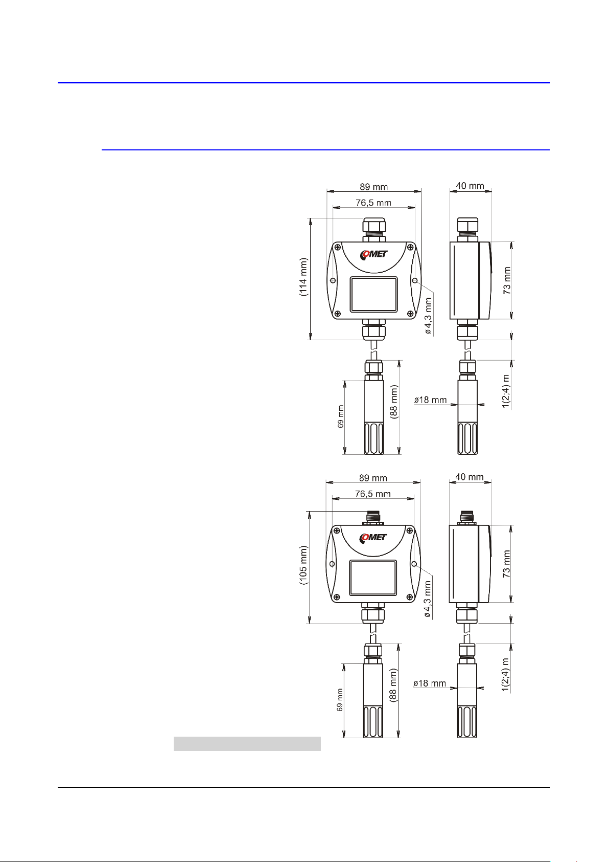
Dimensions
T3111
T3111Ex
T3111L
IE-SNC-T3111-13 17

T3111P
18 IE-SNC-T3111-13

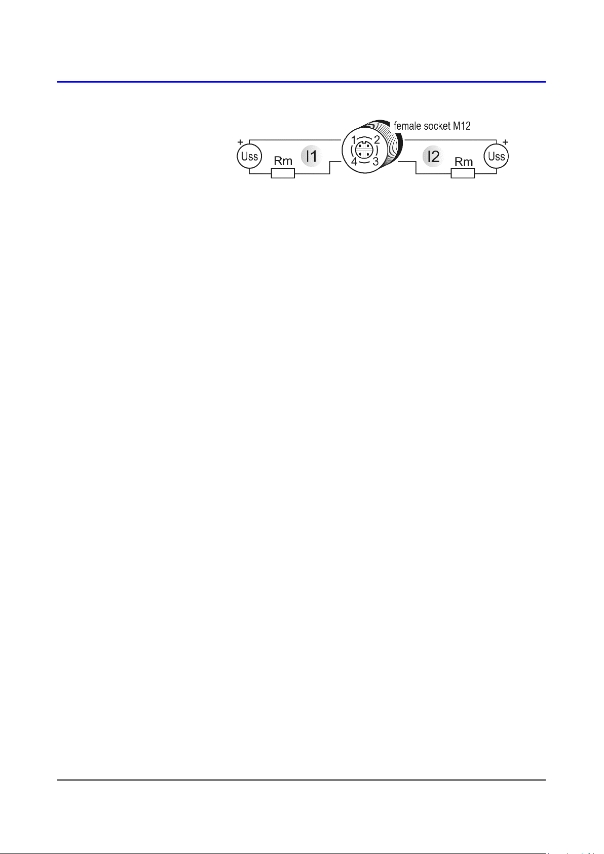
Typical application wiring
T3111
T3111P
Loop resistance value Rc = Rm + resistance of wires shall
fulfill the condition Rc[Ω] < 40 x Uss[V] – 360.
T3111Ex
Loop resistance value Rc = Rm + Rs + resistance of wires
shall fulfill the condition Rc[Ω] < 40 x Uss[V] – 360.
Intrinsically safe parameters of the transmitter:
Ui = 30 V, Ii = 100 mA, Io = 22 mA, Ci ~ 0, Li ~ 0
IE-SNC-T3111-13 19
T3111L
Loop resistance value Rc = Rm + resistance of wires shall
fulfill the condition Rc[Ω] < 40 x Uss[V] – 360.
20 IE-SNC-T3111-13
Appendix A
The probe for measuring the moisture of compressed air should be placed
directly on the pressure pipelines to achieve higher measurement accuracy
and fast response times. But they are cases where such placement is not
possible. The reason is the high air speed, high temperature, high pollution,
small diameter pipes, etc. Such situation can be solved by placing the probe
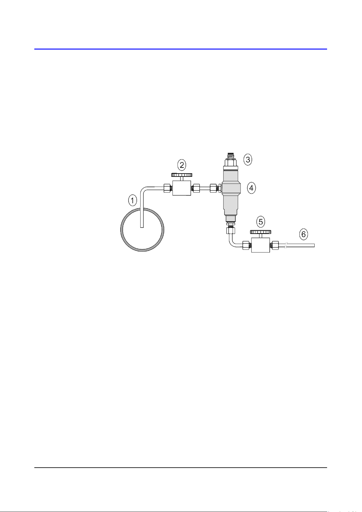
into the flow measuring chamber. The picture shows the basic layout of the
sampling system with chamber SH- PP.
1 ….sampling 4 ….flow chamber SH-PP
2 ….closing valve 5 ….closing valve
3 ….probe 6 ….outlet tube
sampling (1) - end of the tube placed in the centre of pressure pipelines
(distribution of moisture in the pipe cross-section is not homogeneous).
To achieve fast response times to shorten the length of the sample tubes
to a minimum (a few meters).
closing valve (2) - allows access to the sample system without interrupting
the main line
closing valve (5) - the sample flow is regulated by this valve. Measurement
accuracy is not typically affected by the sample flow rate, only the
response time of measurement is increased with decreasing value of
sample flow rate.
outlet tube (6) - if the measured sample of air is released into the
atmosphere, select the length of the outlet tube of 1.5 m (recommended
for tube diameter 6mm). The reason is to ensure the accuracy of the
sample in the flow chamber and avoid back diffusion of moisture from the
ambient air..
That basic structure of sampling system can be supplemented with filters,
coolers, flow measurement, pressure measurement, etc. For the accurate
operation of sampling system is important to ensure perfect tightness of all
connections and to use corrosion-resistant materials. Tube inclination is
chosen so as to avoid the accumulation of fluid in the system.
IE-SNC-T3111-13 21

Technical specification – flow chamber SH-PP
Material of flow chamber: stainless steel (DIN 1.4301)
Inlet and outlet connection: G1/8
Probe connection: G1/2
Sample flow rate: 0.1 to 3 l/min
Operating pressure: up to 25 bar
Weight: 580 g
Note: Screw-coupling not included
22 IE-SNC-T3111-13
 Loading...