

Page 1

LOGGER S3541
Temperature and relative humidity logger with two 0-5V inputs
Instruction Manual
Page 2

Instruction manual for use of temperature and RH logger S3541
Logger is designed for measurement and record of ambient temperature, relative humidity and
two signals 0-5Vdc. Measuring sensors of temperature and humidity are attached to logger.
Measured values including calculated dew point temperature are displayed on the two-line LCD
display and are stored in selectable time interval to internal nonvolatile memory. All logger control
and setting are performed from the PC and password is applicable. It is enabled to switch ON and
OFF the logger by delivered magnet (this possibility can be in configuration disabled). Start/stop
magnet enables also to clear the minimum and maximum value memory. Start/stop magnet enables
also to c lear the minimum a nd maximum value memo ry. It is also enabled to program automatic
start in certain day and time (for one month forward).
Minimum and maximum measured values can be displayed (display switches to actual
measured values and min/max values automatically). It is also possible to operate logger with
switched OFF display. Short display of actual measured values is enabled by means of magnet.
Switched ON logger every 10 seconds (independently on logging interval) updates MIN/MAX
memory, compares measured values of each quantity with two adjustable limits for each quantity
and exceeding of limits is indicated on the display (alarm function). Also memory alarm mode is
selectable, when alarm is indicated permanently till alarm memory reset. Alarm function is enabled
or disabled for each quantity individually.
Logging mode can be adjusted as non-cyclic, when logging stops after filling the memory. In
cyclic mode oldest stored values are overwritten by new. In addition logging mode can be selected
when logging is active only if measured value is out of adjusted alarm limits.
Stored values can be transferred from logger memory to the PC by means of communication
adapter. Communication adapter can be connected to the logger permanently – data logging is not
interrupted even if data download appears.
Logger evaluates minimum battery voltage and its drop below allowed limit is indicated on the
display. At the same time value of remaining battery capacity is available by means of the PC
program and appears on the logger LCD in % (every time after switch ON).
Technical parameters:
Measuring parameters:
Ambient temperature (RTD sensor Pt1000/3850ppm):
Measuring range: -30 to +70 °C
Resolution: 0.1 °C
Accuracy: ± 0.4 °C
Relative humidity (reading is temperature compensated at entire temperature range):
Measuring range: 0 to 100 %RH
Resolution: 0.1 %RH
Accuracy: ± 2.5 %RH from 5 to 95 %RH at 23 °C
Dew point (value calculated from temperature and humidity):
Range: -60 to +70 °C
Resolution: 0.1 °C
Accuracy: ± 0.5 °C from 30 to 95 %RH
Voltage inputs (IN1, IN2):
Voltage measuring range: 0 to 5 V dc
Effective resolution: 13 bits
Accuracy: ±0,2 % FS
Input resistance: approximately 100k ohms
Response time with plastic sensor cover (air flow approximately 1 m/s):
temperature: t63 < 2 min, t90 < 8 min (temperature step 20 °C)
2 IE-LOG-S3541-04
Page 3

relative humidity: t63 < 15 s, t90 < 50 s (humidity step 30 %RH, constant temperature)
Connection of input signals: by shielded cable via Canon 9 pins connector
Measuring interval, alarm evaluation, MIN/MAX memory update and display refresh: 10 s
Logging interval to memory: 10 s to 24 h (20 steps)
Total memory capacity:
for non cyclic mode 32 504 records
for cyclic mode 28 896 records
Specified values are maximum possible and can be reached only if record is not interrupted
(since last memory erasing)
Communication with computer: via RS232 (serial port) by means of COM adapter or USB
port by means of USB adapter; data transfer from logger via communication adapter is
optical
Real time clock: adjustable from computer, integrated calendar including leap years
Error of internal RTC: < 200 ppm (i.e. 0.02 %, 17.28 s in 24 h)
Power: Lithium battery 3.6 V size AA
Typical battery life: 2 years
Protection: electronics IP67, sensors are protected by a cover with IP30 protection
Operational conditions:
Operational temperature range: -30 to +70 °C
Operational humidity range: 0 to 100 %RH
Specification of outer characteristics accordingly to EN33-2000-3: normal environment
accordingly to appendix NM: AE1, AN1, AR1, BE1
Operational position: negligible
Logger installation: by self adhesive Dual Lock, applied to clean, flat surface
Not allowed manipulation: it is not allowed to remove sensor cover and mechanically
damage sensor under cover. Sensors of temperature and humidity should not get to
direct contact with water or other fluids.
Limit condition: temperature -40 to +70 °C, humidity 0 to 100 %RH
Limit condition: maximum voltage at measuring input -1 to +7V dc
Storing condition: temperature -40 to +85 °C, humidity 0 to 100 %RH
Dimensions: 93 x 64 x 29 mm
Weight including battery: approximately 130 g
Material of the case: polycarbonate
Logger operation
Logger comes complete with installed battery and switched OFF. Before operation it is
necessary by means of installed user PC software to set logging parameters and other features. Free
user program is available to download at
www.cometsystem.cz . For communication with the PC a
communication adapter is necessary (not included in delivery). For connection via RS232 serial
port it is necessary to use COM ADAPTER, for connection via USB port it is necessary to use USB
ADAPTER. Connect adapter connector to proper computer port and plug the adapter to the guide
slots on the side of logger.
IE-LOG-S3541-04 3
Page 4
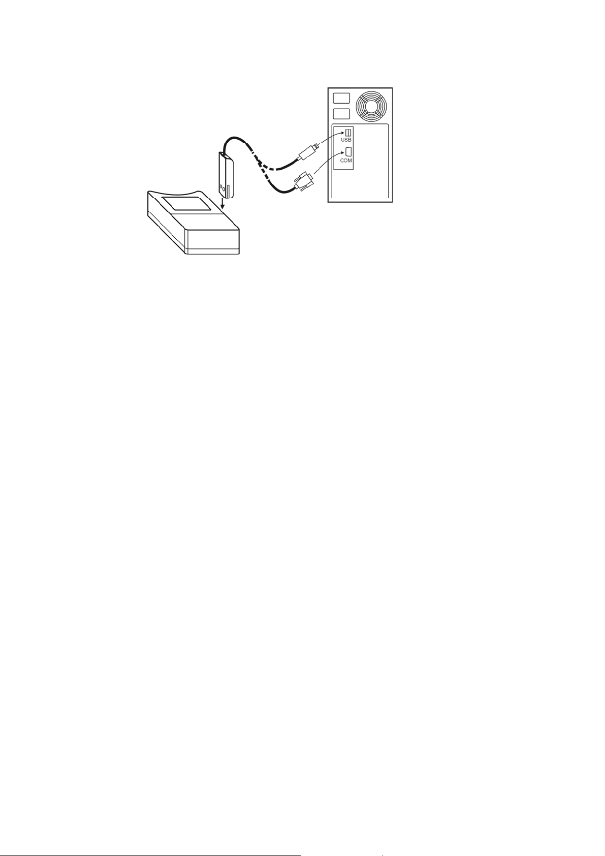
Connecting logger to the computer by means of communication adapter
Notice: USB connector can be located also from the computer front side
After connecting the logger to the computer reading of logger info is enabled by means of the
PC software and also setting of the instrument accordingly to the user needs (menu Configuration /
Setting of instrument parameters).
Note: voltage inputs IN1 and IN2 are mapped from the PC program as channels 3 and 4, i.e. set
desired parameters for IN1 at channel 3 card and desired parameters for IN2 at channel 4 card.
Before logging start it is necessary:
• check or optionally set the logger real time clock
• select suitable logging interval
• select logging mode (cyclic or non cyclic)
• switch ON the logger (or switch OFF, if it is about to be switched ON by magnet or
automatically with delayed start)
• enable or disable the option to switch ON the logger by magnet
• enable or disable the option to switch OFF the logger by magnet
• enable or disable the option to clear minimum and maximum value memory by magnet
• set date and time of logger automatic switching ON logger or disable this option
• select if record runs permanently or only if alarm is active
• If alarms are about to be applied, set both limits for each measured quantity and enable
alarm
• optionally enable permanent alarm indication (alarm with memory)
• switch ON or switch OFF display logger
• optionally switch ON displaying of MIN/MAX values on the LCD
• reset memory of MIN/MAX values (if needed)
• check free space in data memory, optionally erase data memory of the logger
• enter password if protection against unauthorized manipulation with the logger is necessary
Logging interval between to subsequent measurements is specified by the user. Memorizing of the
first value is synchronized with the internal real time clock, so the logging is performed at sharp
multiples of minutes, hours and days. E.g. after starting the logging with the 15 minute interval the
first value is not stored immediately, but after the internal clock gets the status of a quarter, a half or
a whole hour. After starting the logging with the 6 hour interval the first value is stored at that
whole hour to perform the storing also at 00.00, i.e. at the beginning of the day. First storing is
performed at 6.00,12.00, 18.00 or 00.00hour - at the hour from the above nearest to the logging
4 IE-LOG-S3541-04
Page 5
start. After communication with computer or after start by magnet logger automatically waits for
the nearest whole multiple of time and then first measurement is performed. This is also necessary
to take into account when setting time of automatic logger switch ON.
Notice: If logger operates as permanently connected to the computer, using of magnet
start/stop is disabled.
To enable the logger control by magnet is suitable only in cases, when possibility of
unauthorized manipulation to the logger operation is eliminated.
Connection to voltage output of a transducer
Connect logger to transducer output by shielded cable with 9 pins Canon female connector. If
IP67 rating is required, it is necessary to use watertight connector K0921 – optional accessory.
Connect positive pole of the sensor 1 output to pin 6 and negative pole to pin 5. Connect positive
pole of the sensor 2 output to pin 8 and negative pole to pin 5. Inputs from both sensors are galvanic
connected, therefore sensors should be powered from one source. Reversing of polarity does not
damage the logger, but logger does not measure correctly (zero voltage is recorded) – permanent
reversal of poles is not allowed (increased current consumption from the battery).
Notice: pin 9 is galvanic connected to pin 5 (signal input negative pole) – for connection of the
cable is possible to use any of the pins.
Reading on the display in usual operation (logger switched ON)
After switching ON the logger all LCD symbols are displayed for checking
the display.
Then actual date and time in logger is displayed for approximately 4 s.
Consequently reading of estimated remaining battery capacity for
approximately 2 s is displayed (values 0 to 100%).
If display is switched ON, actual reading of measured values is displayed -
ambient temperature (°C) on the LCD upper line, relative humidity (%RH)
on the LCD lower line. Symbol LOG indicates data logging in progress – if
it blinks, data memory is filled up to more than 90%.
Every 5 s display is automatically switched to displaying of other measured
or calculated quantity.
Logger now displays ambient temperature and dew point temperature (LCD
line marked by symbol DP).
IE-LOG-S3541-04 5
Page 6
At last values from channel IN1 (upper line, symbol 1) and channel IN2
(lower line, symbol 2)
Switched ON logger permanently (with 10 s interval) updates memory of
minimum and maximum values of each measured (or calculated) quantity. If
displaying of MIN/MAX values is selected, minimum measured values are
displayed step by step (indicated by symbol MIN) and then similarly
maximum measured values of all quantities (indicated by symbol MAX).
The entire cycle is repeated periodically, i.e. reading of actual measured
values follows.
If display is switched OFF, all above readings are displayed up to
estimated remaining battery capacity and then display goes out. If logger is
switched ON symbol LOG is displayed (it blinks if memory occupation is
higher than 90%).
If display is OFF and logger is in mode when record runs only when alarm
is active, the LOG symbol is replaced by adjacent symbol "–" (hyphen). It
appears in case, all measured values are inside of adjusted alarm limits and
data logging therefore does not run. Displayed symbol indicates logger is
ON.
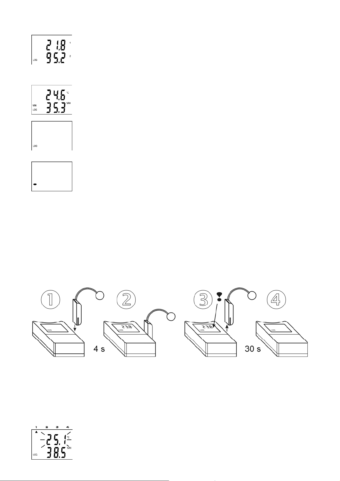
If information on actual measured values is needed, it is possible anytime to display reading
display by means of the magnet (only if communication adapter is not connected permanently).
Plug magnet into guide slots from logger front side for approximately 4 s and wait till reading on
the display appears. If logger has enabled the function switch OFF by magnet, resp. MIN/MAX
memory clear by magnet, do not remove magnet from guide slots before decimal point symbol goes
out – logger would be switched OFF, resp. MIN/MAX memory would be cleared! Display reading
initialized by magnet goes out automatically after 30 s. Remove magnet from slots anytime during
actual reading is ON or later.
Temporary displaying of actual reading by magnet
Alarm indication on the display
It is necessary to enable alarm function from the PC and set for each quantity lower and upper
limit. If measured value is inside of set limits, alarm of proper quantity is not active. If value of
measured quantity gets outside of set limits, alarm of proper quantity is active and it is indicated on
the display. It is possible to select "memory alarm mode" when alarm is indicated permanently up
to reset from the PC.
Active alarm is indicated (if display is ON) by blinking of the value of
proper quantity on the display and arrow symbol appears at the LCD upper
6
IE-LOG-S3541-04
Page 7
side at the same time. Arrow 1 indicates active alarm for ambient
temperature, arrow 2 for relative humidity, arrow 3 for channel IN1 and
arrow 4 for channel IN2 and dew point temperature.
Notice: if logger is operated at low temperature (below approximately
-5 °C), alarm indication by blinking can be indistinct. Indication by arrows
works correctly.
Messages displayed on the LCD beyond usual operation
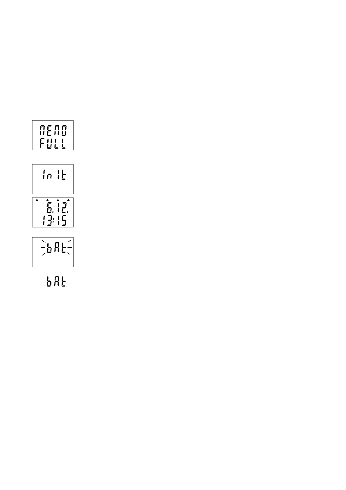
If measured value is out of the measurable or displayable range numeric
reading is replaced by hyphens.
If memory is totally full filled in non-cyclic logging mode, logger is
switched OFF and message MEMO FULL appears on the LCD. It appears
also if logger is operated with switched OFF display.
New initialization of logger can occur in switching ON the logger
(immediately after displaying of all LCD segments for checking) e.g. after
replacement of totally discharged battery for new one. State is indicated by
INIT reading. It can be displayed for about 12 s.
If battery voltage drop occurred since last internal clock setting below
critical limit or battery disconnection for longer period than approximately
30 s, after display switch ON (during date and time display) all four arrows
appears as warning to check or set it again from the computer. However all
logger functions work without limitation.
If reading BAT is displayed periodically on LCD upper line (for 1 s with 10
s interval), the end of estimated battery life is coming – however logger
functions are not limited. Replace battery as soon as possible!
If reading BAT is displayed permanently, battery voltage is low and logger
is not possible to switch ON. If logger was switched ON before it, data
logging is stopped and logger is switched OFF. Communication
with computer can temporarily work. Replace battery as soon as possible!
Start / stop by magnet
The function must be enabled from the PC before. If only switching OFF by magnet is enabled,
it is of course necessary to switch ON the logger from the computer.
Notice: It is not possible to combine function switching OFF by magnet and MIN/MAX
memory clear by magnet! User software enables only one of them to select.
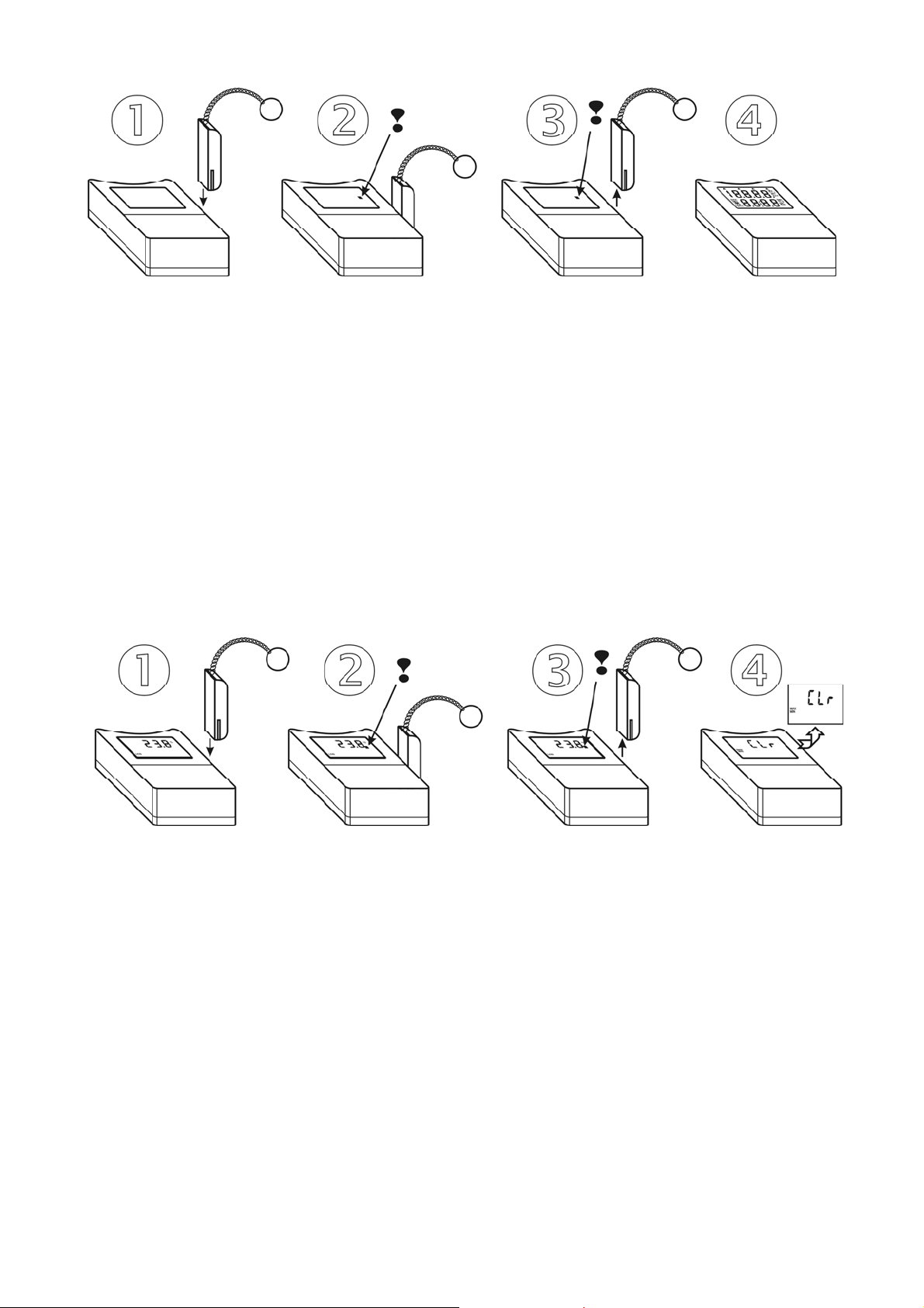
Switching the logger ON by magnet
Plug magnet to guide slots from logger front side and wait approximately 1 s for decimal point
appears right on LCD upper line. After appearance it is necessary immediately (till indication point
is displayed) to remove magnet from guide slots and logger switches ON.
IE-LOG-S3541-04 7
Page 8
Switching the logger OFF by magnet
The procedure is identical with the above procedure for switching ON. If decimal point does
not appear after 1 s, it is necessary remove the magnet and repeat the procedure.
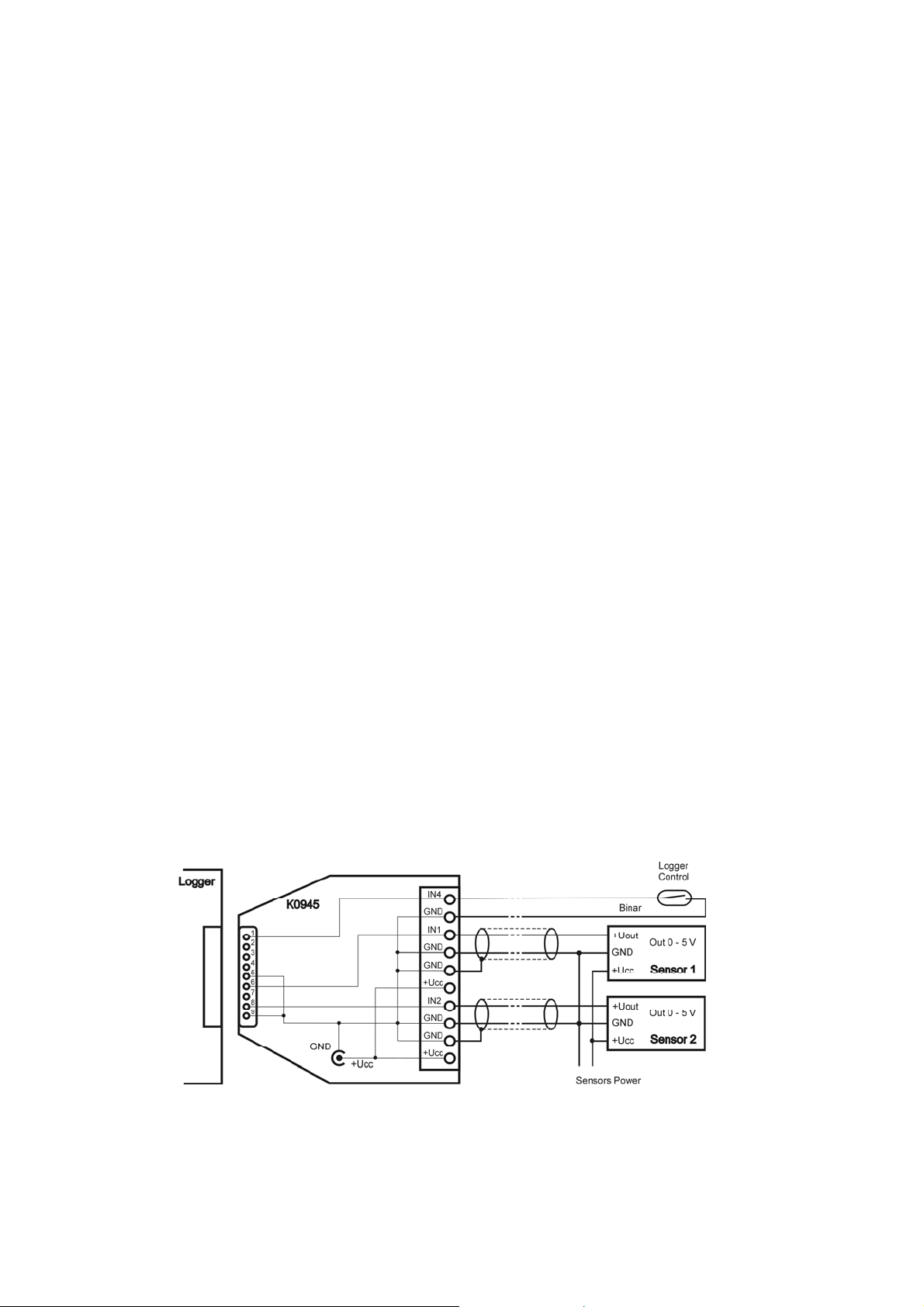
Reset of MIN/MAX values by magnet
Function enables to clear MIN/MAX values by magnet without using computer. It is necessary
to enable the function from the PC software before.
Notice: It is not possible to combine this function with function of switching logger OFF by
magnet! User software enables to select only one of them (or none).
Plug magnet to guide slots from logger front side and wait approximately 1 s for decimal point
appears right on LCD upper line. After decimal point appearance it is necessary immediately (till
indication point is displayed) to remove magnet from guide slots. Reading CLR MIN MAX appears
for several seconds and MIN/MAX values will be cleared.
Battery replacement
Low battery is indicated on the display by blinking of reading "BAT". It can be displayed
permanently, if battery voltage is too low. Replace the battery for new one. Applied is Lithium
battery 3,6 V, size AA. Battery is located under logger lid.
Warning: near battery fragile glass reed contact is located – be careful not to damage it. Be
careful in battery replacement!
Replacement procedure:
• unscrew four corner screws and remove the lid
• remove old battery by pulling the glued tape
• insert new battery respecting the correct polarity (see symbols + and – near battery holder). If
you connect new battery up to 30 s, all logger settings remain unchanged. In the opposite case
check by means of PC program all settings, especially the real time clock in logger. Attention,
inserted battery with incorrect polarity causes logger damage!
• put the lid back again and screw four screws. Be careful to have the rubber sealing properly in
the slot and tighten the screws properly to ensure the water resistance of the instrument.
8 IE-LOG-S3541-04
Page 9
• connect logger to the computer and write to it the information on battery replacement. This
step is necessary to evaluate properly the remaining battery capacity.
Old battery or logger itself (after its life) is necessary to liquidate ecologically!
Instruments passed the following electromagnetic compatibility (EMC) tests:
radiation: EN 55022 class B
immunity: EN 61000-4-2 (levels 4/8 kV, class A)
EN 61000-4-3 (intensity of electromagnetic field 3 V/m, class A)
EN 61000-4-4 only types with external probes (levels 1/0,5 kV, class A)
EN 61000-4-6 only types with external probes (intensity of electromagnetic
field 3 V/m, class A)
APPENDIX
Interconnection of logger to input signals by means of optional K0945 adapter with screw
terminals
If no protection against water is required, input signals can be easily connected by means of the
K0945 adapter (optional accessory). Plug adapter to logger Canon connector and connect input
signals to screw terminals in accordance with drawings below. The IP rating is only IP20 and the IP
rating of the logger (IP67) is not possible to apply.
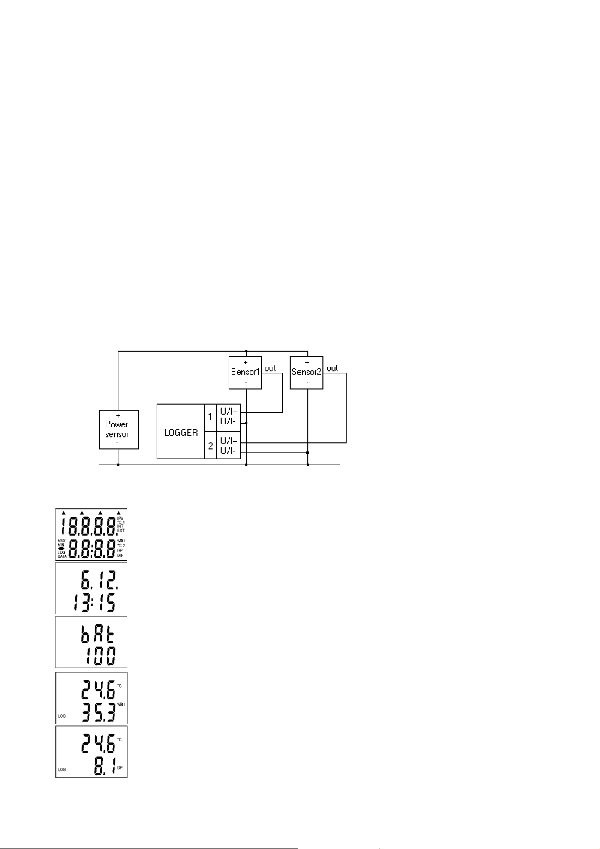
Connection to sensor signal. Power supply is located near the sensor:
Connection to sensor signal. Power supply is located near the logger:
IE-LOG-S3541-04 9
Page 10
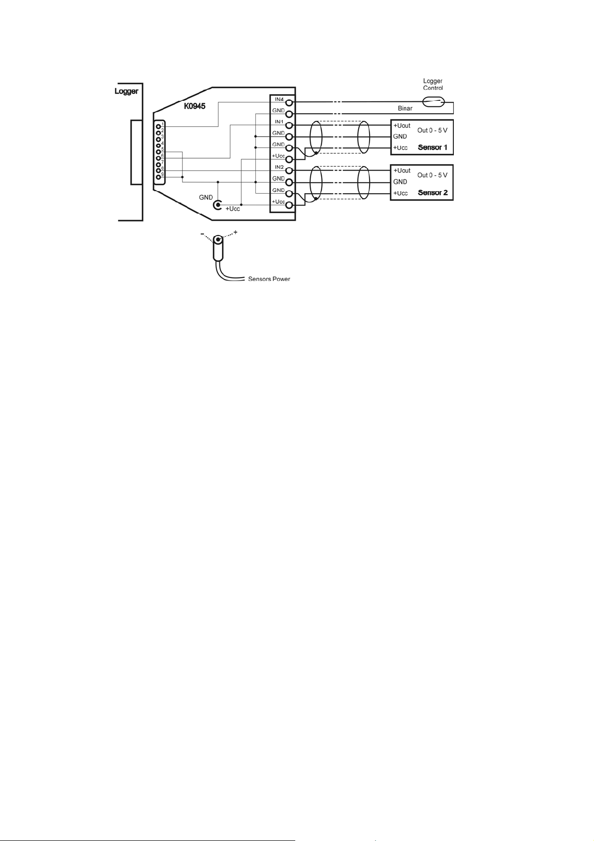
At this case sensor is possible to power e.g. from ac/dc adapter, connected via coaxial power
connector to K0945 adapter. Supply voltage and the power of the applied ac/dc adapter depend on
types of connected sensors.
10 IE-LOG-S3541-04
 Loading...