

Page 1

VoIP Telephone Adaptor
User Manual
Model Nr. IPTEL-H / IPTEL-S / IPTEL-M
V1.7
English Version
Copyright 2004 ®
Page 2
Quick Guide
IPTEL
IPTEL
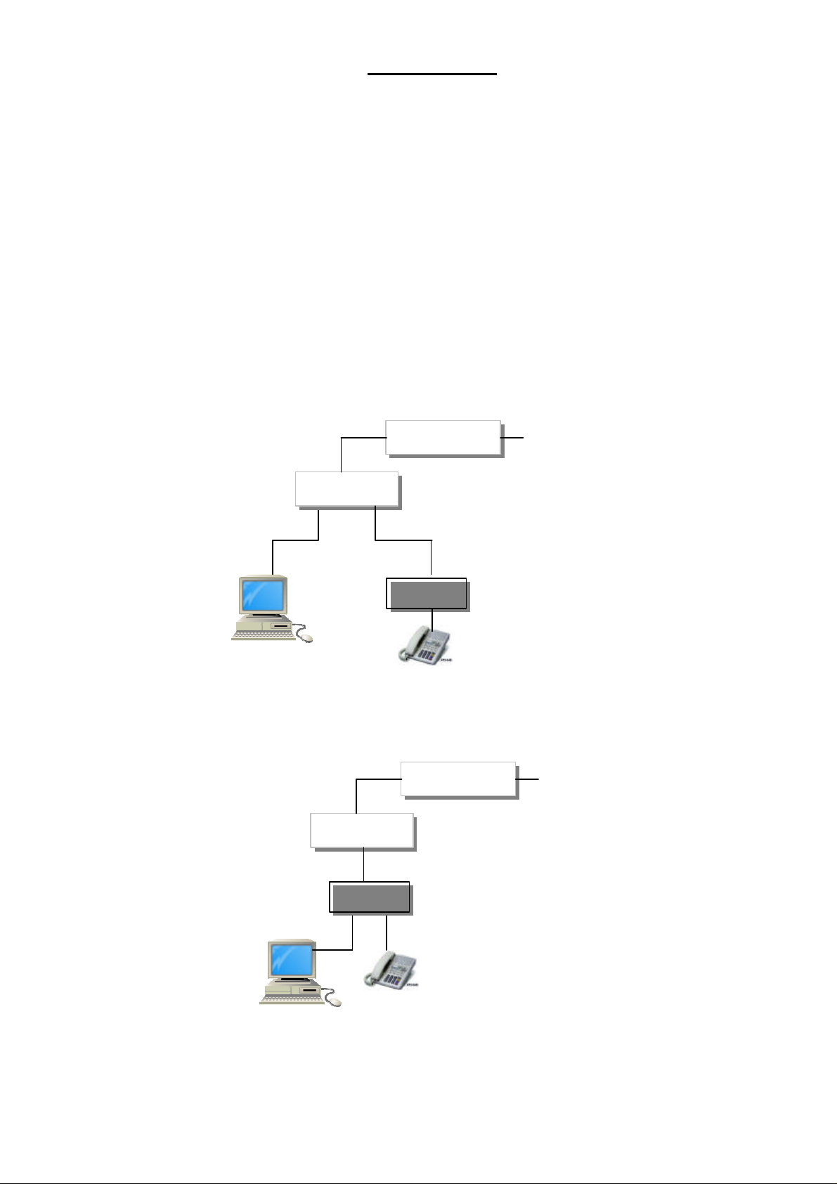
Step 1: Broadband (ADSL/Cable Modem) Connections For IPTEL
A. Connect IPTEL-H / IPTEL-S / IPTEL-M RJ45 LAN port to Router/ADSL as one of the
following connections.
B. Connect IPTEL RJ45 PC port to PC using a Category 5 LAN cable.
C. Connect IPTEL-H / IPTEL-S / IPTEL-M RJ11 PHONE port to a Telephone Set.
D. Connect Power Adaptor to the POWER outlet. After flashing, the POWER LED will be
lit.
E. Pick up the phone, the PHONE LED will be lit, and you should hear a dial tone.
F. Enable and set NAT router “DMZ” address (e.g. 192.168.1.150) to be used for IPTEL-H
/ IPTEL-S / IPTEL-M IP address.
a. ADSL Connections with NAT Router for IPTEL
NAT Router
PC
b. ADSL Connections with NAT Router for IPTEL
NAT Router
LAN
PC
ADSL Modem
Router IP: 192.168.1.254
DMZ IP: 192.168.1.150
IPTEL IP: 192.168.1.150 (#11)
Subnet Mask: 255.255.255.0 (#12)
Router IP: 192.168.1.254 (#13)
Telephone
ADSL Modem
Router IP: 192.168.1.254
DMZ IP: 192.168.1.150
IPTEL IP: 192.168.1.150 (#11)
Subnet Mask: 255.255.255.0 (#12)
Router IP: 192.168.1.254 (#13)
Telephone
Page 3
IPTEL
IPTEL
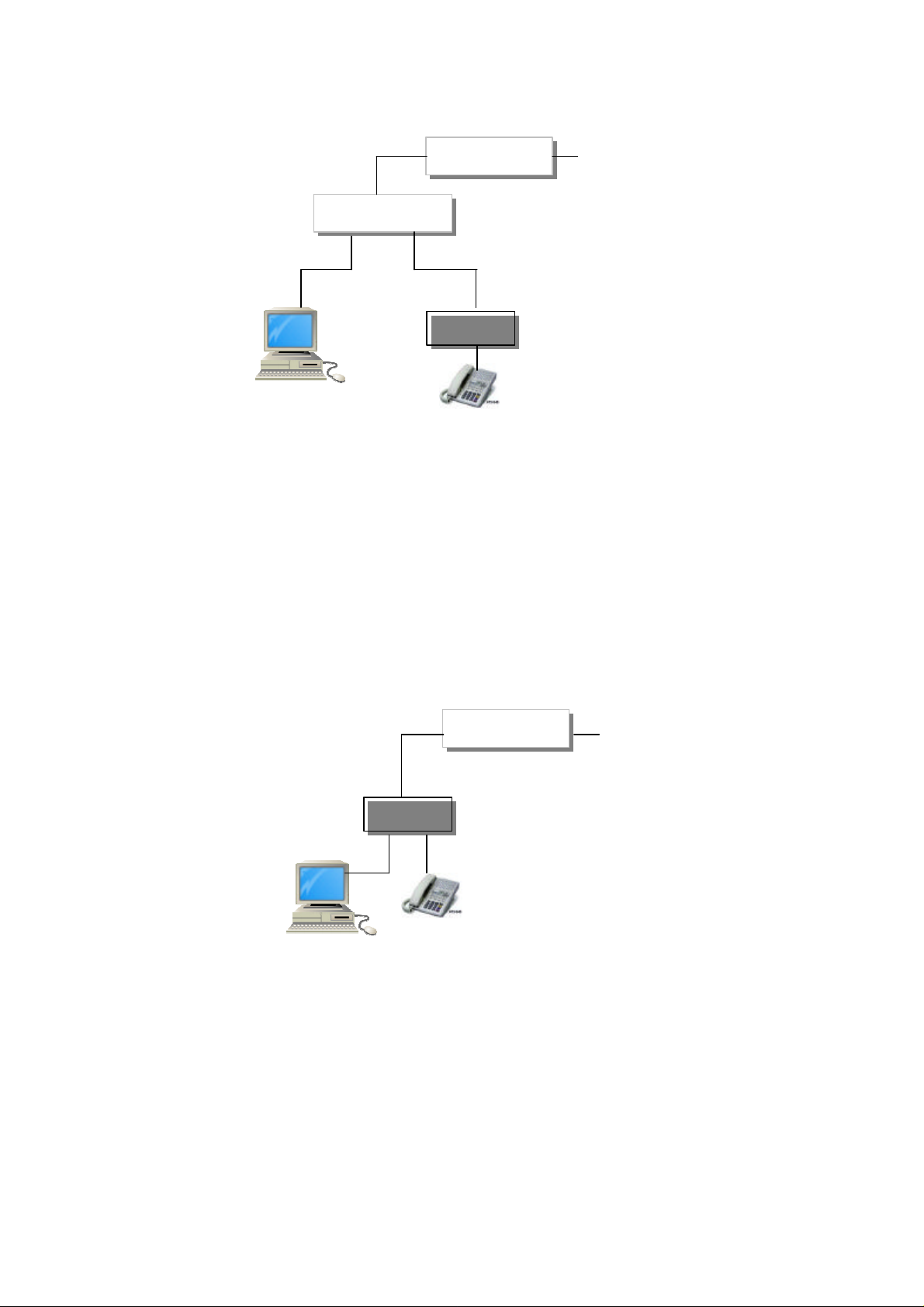
c. ADSL Connections without Router for IPTEL
(refer to PPPoE section in Chapter 9. PC Telnet Command Mode)
Ethernet Switch
PC
1. Run From PC: Telnet 192.168.1.150
2. Set PPPoE (#051)
3. Enter PPPoE Username (#06nnnnnn)
4. Enter PPPoE Password (#07xxxxxx)
5. Enter “? ” or Pick up phone to enable PPPoE
Note: To disable PPPoE, simply press #050# from telephone
d. ADSL Connections without Router for IPTEL
ADSL Modem
IPTEL IP: 192.168.1.150 (#11)
Subnet Mask: 255.255.255.0 (#12)
Router IP: 192.168.1.254 (#13)
Telephone
(refer to PPPoE section in Chapter 9. PC Telnet Command Mode)
LAN
PC
1. Run From PC: Telnet 192.168.1.150
2. Set PPPoE (#051)
3. Enter PPPoE Username (#06nnnnnn)
4. Enter PPPoE Password (#07xxxxxx)
5. Enter “? ” or Pick up phone to enable PPPoE
Note: To disable PPPoE, simply press #050# from telephone
ADSL Modem
IPTEL IP: 192.168.1.150 (#11)
Subnet Mask: 255.255.255.0 (#12)
Router IP: 192.168.1.254 (#13)
Telephone
Page 4

Step 2: IP Settings for IPTEL-H / IPTEL-S / IPTEL-M with Static IP
A. Prepare for IPTEL IP Address, Subnet Mask, and Router IP Address. (*)
B. Pick up the phone, and you should hear a dial tone.
C. Press #11 + IP Address to enter IPTEL IP address
Example: Press #11061020102004 if IPTEL static IP address is 61.20.102.4
D. Press #12 + Subnet Mask to enter the subnet mask
Example: Press #12255255255000 if subnet mask is 255.255.255.0
E. Press #13 + Router IP Address to enter the Router IP address
Example: Press #13061020102254 if Router IP address is 61.20.102.254
(*)Note that the static IP address is available from your Internet Service Provider. When
connected with NAT router as above for ADSL dynamic IP, the IP Address, Subnet Mask,
and Router IP Address are 192.168.1.150, 255.255.255.0, and 192.168.1.254,
respectively. Please note that you must press 3 digits for each byte of the IP
address.
Step 3: Making Point-To-Point Static IP Calls
A. Pick up the phone, and you should hear a dial tone.
B. Press 061066159236 to call the party with IP address of 61.66.159.236
In a moment, you should hear the ring back tone, and wait for the called party to answer,
or you will hear a busy tone when the dialed number is busy or not available.
Step 4: Making Point-To-Multiport Gateway Static IP Calls
A. Pick up the phone, and you should hear a dial tone.
B. Press 061219023102900 to call the VG400 gateway with static IP address
61.219.23.102 at extension port 900.
In a moment, you should hear the ring back tone, and wait for the called party to answer,
or you will hear a busy tone when the dialed number is busy or not available.
Step 5: Making Point-To-Point Gatekeeper Dynamic IP Calls
A. The PHONE LED should be flashing to indicate the IPTEL is successfully registered in
the Gatekeeper with IP address of #21 command.
B. Pick up the phone, and you should hear a dial tone.
C. Press 109 to call the party with alias phone number 109 registered in the
gatekeeper. The gatekeeper pre-registered alias phone number is shown at the
bottom of each IPTEL.
For more details of Gatekeeper dynamic IP calls, please refer to Chapter 9. PC Telnet
Command Modes.
Page 5

TABLE OF CONTENTS
1. Introductions ……………………………………………………
2. Features ……………………………………………………………
3. Standard Compliances ………………………………………
4. Packing Contents ………………………………………………
5. LED Indicators …………………………………………………
6. Installations & IP Configurations ………………………
7. Telephone Keypad Dialing …………………………………
8. Telephone Command Modes ………………………………
Hot Line Mode Operations……………………………
9. PC Telnet Command Modes ………………………………
Gatekeeper Mode Operations ………………………
PPPoE for ADSL Dynamic IP ………………………
10. Commands Summary ………………………………………
11. Firmware upgrade/Download Procedures…………
Remote download from telephone …………………
Local PC download from telephone ………………
1
1
1
2
2
3
4
5
6
7
10
11
12
14
14
15
Page 6

1. Introduction
The IPTEL-H / IPTEL-S / IPTEL-M is a single port Telephone Adaptor (TA) for Voice over
IP (VoIP), and it supports H.323, and SIP (optional) Protocols. Connecting to the Internet
with a plain old telephone set (POTS), the IPTEL can make a voice call over the Internet
from one IP to another one.
With additional PC LAN port comparing to IPTEL, the IPTEL allows connection to a
Notebook PC when using in the office. With portable and user friendly design, the
IPTEL-H / IPTEL-S / IPTEL-M is very suitable for ITSP (Internet Telephony Service
Providers) customers and SOHO users to make a voice call on the Internet.
Note that each IPTEL-H / IPTEL-S / IPTEL-M will need an IP address, a subnet mask,
and its gateway IP address for its own use. These three are available from your
Internet service provider. The Media Access Control (MAC) hardware address is
indicated at the bottom of IPTEL-H / IPTEL-S / IPTEL-M.
2. Features
The IPTEL-H / IPTEL-S / IPTEL -M VoIP TA is equipped with one RJ11 connector for POTS,
and one RJ45 LAN connector for Router Connection. There is an extra RJ45 LAN port
with IPTEL for connection to additional Notebook PC. The IPTEL-H / IPTEL-S / IPTEL-M
features as follows;
Three LED Indicators: POWER, PHONE, LAN
Direct Static IP Dialing
GateKeeper Mode Dialing
PPPoE for Dynamic IP
Hot Line Mode
Remote/Local TFTP Firmware Download/Update
3. Standard Compliances
The IPTEL-H supports for the following standards
VoIP Protocol: ITU-T H.323 V4 or MGCP or SIP (RFC3261)
Speech Codec: ITU-T G.711A/u-Law, G.723.1, G.729A/B/AB (optional)
Echo Cancellation: ITU-T G.165 16 ms
1
Page 7

4. Packing Contents
Inside the package you should find:
(1) One IPTEL Phone
(2) One DC Power Adaptor
(3) One Phone cable
(4) One LAN cable
Please check if the packing is damaged before unpacking or any component is missing. If
so, please contact your distributor.
5. LED Indicators
On the front panel of IPTEL, there are three LED indicators as follows;
Power : On indicates the power is normal
Flashing once every minute indicates Router IP is NOT found
Continuous Flashing indicates PPPoE is NOT working
PHONE: On indicates the telephone is offhook
Continuous Flashing indicates successful Gatekeeper registration for IPTEL
LAN : LAN activity
Continuous Flashing indicates VoIP is in progress
2
Page 8

6. Installations & IP Configurations
1. Connect IPTEL RJ45 LAN port to Router using the Category 5 LAN cable.
2. Connect IPTEL RJ45 PC port to Notebook PC using a Category 5 LAN cable.
3. Connect IPTEL RJ11 PHONE port to a Plain Old Telephone Set (POTS).
4. Connect the Power Adaptor (5VDC) to the POWER outlet.
5. The POWER and PHONE LED indicators will start flashing for about 10 seconds and
OFF for a while, then flashing three times again. After the POWER LED is lit
constantly, the IPTEL will be ready for configuration and VoIP calls. If the PHONE
LED keep flashing, is idle, it indicates that IPTEL has successfully registered in the
Gatekeeper (Refer to Section 7 & 8 for Gatekeeper Mode).
6. Pick up the phone, the PHONE LED will be lit and you should hear a dial tone.
7. Prepare for the IPTEL an IP address, a Subnet mask, and a Router IP address before
making a VoIP call. These three can be available from your Internet Service
Provider. The defaults of IP Address, Subnet mask, and Router IP Address for IPTEL
are 192.168.1.150, 255.255.255.0, and 192.168.1.254.
8. Configurations Command modes can be entered from either the telephone or PC
Telnet session and can be stored and remains in the flash memory even when the
power is off.
6.1 IP Configurations From Telephone
1) Pick up the phone, the PHONE will be lit and you should hear a dial tone.
2) Enter the IPTEL an IP Address, a Subnet mask, and a Router IP address as the
following.
Press #11 + IP Address
Example: Press #11061020102004 if the IPTEL IP Address is 61.20.102.4
Press #12 + Subnet mask
Example: Press #12255255255000 if the Subnet mask is 255.255.255.0
Press #13 + Router IP Address
Example: Press #13061020102254 if the Router IP address is 61.20.102.254
Note that you must press 3 digits for each byte of the IP address.
3) After entering each item, you will hear the dial tone for confirmation. If not, you
will hear a busy tone indicating an invalid configuration. The defaults of IP Address,
Subnet mask, and Router IP Address for IPTEL are 192.168.1.150, 255.255.255.0, and
192.168.1.254, respectively.
3
Page 9

7. Telephone Keypad Dialing
You may now start making a VOIP call by dialing the IP address directly from the
telephone. There are 5 different types of dialing for IPTEL;
1) Direct Static IP Dialing (#200):
12-15 digits for Point-to-Point and Point-to-Multiport Gateway static IP dialing.
2) Direct Static IP Dialing + Gatekeeper Mode Dialing (#201):
1-11 digits for Gatekeeper Mode dynamic IP dialing, and 12-15 digits for direct
Point-to-Point and Point-to-Multiport Gateway static IP dialing.
3) Gatekeeper dialing mode (#202):
1-48 digits for Gatekeeper and Trunk Gateway such as Cisco 5300
4) Memory dialing (#80 - #99) for stored number dialing
5) Hot-line dialing mode (#401): In 3 seconds after hang-up, the number in #99 will be
dialed.
7.1 Point-to-Point Static IP calls
1) Press the IP address of the party you want to call as the following.
Example: Press 211020102110 to call the party with IP address 211.20.102.110
In 3 seconds, you should hear the ring back tone, and wait for the called party to
answer, or you will hear a busy tone when the dialed number is busy or not available.
7.2 Point-to-Multiport Gateway Static IP calls
1) Press the IP address + the extension port number
Example: Press 061219023102900 to call the party with IP address of
61.219.23.102 at extension port 900.
In 3 seconds, you should hear the ring back tone, and wait for the called party to
answer.
7.3 Point-to-Point Gatekeeper Dynamic IP calls
1) Press the Alias Number
Example: Press 112233 to call the party with alias number 112233 registered in
the gatekeeper. (Refer to the Gatekeeper Mode in Section 7 & 8.)
In 3 seconds, you should hear the ring back tone, and wait for the called party to
answer.
7.4 Memory Dial for IP calls
There are 20 memories for use to store IP Addresses and Alias Numbers for IP calls.
To make Memory Dial, simply
Press *N to dial the IP address/Alias Number stored in the N memory (N=80~99)
Example: Press *90 to dial the IP address/Alias Number stored in the N=90
memory.
4
Page 10

8. Telephone Command Modes
The IPTEL provides commands to configure for different features and applications when
making a VoIP call. Configuration commands can be entered from either the telephone
or PC telnet session. This section describes the commands entered from the telephone
keypad. Pick up the phone, the PHONE LED will be lit and you should hear a dial tone.
8.1 Reset to Default from Telephone
Press #01# to reset the default values for IPTEL. Note that this does not change the
password.
8.2 Set Password
Press #01xxx# to set the “xxx” password into IPTEL-H / IPTEL-S / IPTEL-M. If you
forgot the password when using PC telnet session, you may set a new password from
the telephone.
Example: Press #01123# to set the password “123”.
8.3 Storing IP address and Alias Number for Memory Dial
Press #N+IP Address+# to store IP address into the N memory (N is from 80 to 99)
Press #N+Alias Number+# to store alias number into the N memory (N is from 80 to
99)
Example: Press #80061020102110# to store the IP address 211.20.102.110
into the N=80 memory.
Example: Press #90112233# to store the alias number 112233 into the N=90
memory.
Example: Press #99061219023102900# to store the IP address
61.219.23.102 with extension 900 into the N=99 memory (for Hot-Line mode).
You should hear the dial tone, to confirm for the memory storing.
Note that you need to press the “#” to complete configurations from the telephone
set except for the commands #11, #12, #13, #21, which require exact 12 digits.
5
Page 11

Hot Line Mode Operations
IPTEL
IPGATE
Hot Line Mode (#40) allows you to make a direct call at the IP stored in N=99 memory
without dialing. When the Hot Line mode is enabled, you may pick up the phone and
the IPTEL-H / IPTEL-S / IPTEL-M will call the party directly to the preset IP
address/alias number in N=99 memory. Hot-Line Mode is very convenient for calling
to Public Switching Telephone Network (PSTN) number through Multiport Gateway FXO
port.
Internet IP
Hot-Line Mode
FXO
PORT
8.4 Hot Line Mode
Press #400# to disable Hot Line mode (default)
Press #401# to enable Hot Line mode
1. Store the preset IP number in N=99 memory
Example: Press #99211020102110# for IP 211.20.102.110.
Example: Press #99211020102110xxx# for IP 211.20.102.110 ext “xxx”
“xxx” is the IPGATE extension port.
2. Enable Hot Line Mode
Example: Press #401#
You will hear a dial tone for confirmation and hang up the phone to complete the
configuration.
3. Pick up the phone. In 3 seconds, the IPTEL-H / IPTEL-S / IPTEL-M will
automatically call the preset IP number stored in N=99 memory.
4. Note that you may disable the Hot-Line mode by picking up the phone and pressing
#400# in 3 seconds before the IPTEL-H / IPTEL -S / IPTEL-M calling out, and you will
hear a dial tone for confirmation. You may also disable Hot-Line mode by PC telnet
session in Section 8.
6
PSTN
Page 12

9. PC Telnet Command Modes
IPTEL
9.1 Connect IPTEL, or IPTEL, as one of the following diagrams.
a. Standard IPTEL environment
NAT Router
PC
b. Standard IPTEL environment
Router IP: 192.168.1.254
DMZ IP: 192.168.1.150
LAN
PC
If you forgot the current IPTEL-H / IPTEL-S / IPTEL-M IP address, you may enter the new IP
address from telephone by using #11 commands.
ADSL Modem
IPTEL
Router IP: 192.168.1.254
DMZ IP: 192.168.1.150
IPTEL IP: 192.168.1.150 (#11)
Subnet Mask: 255.255.255.0 (#12)
Router IP: 192.168.1.254 (#13)
Telephone
NAT Router
IPTEL IP: 192.168.1.150 (#11)
Subnet Mask: 255.255.255.0 (#12)
Router IP: 192.168.1.254 (#13)
Telephone
7
Page 13

9.2 Key in “telnet 192.168.1.150” from PC Windows [Start] [Run] screen, assuming that the
current IP address is 192.168.1.150. The default IP address for IPTEL-H / IPTEL-S /
IPTEL-M is 192.168.1.150. Note that picking up the phone during the telnet command
mode will logout the telnet session.
9.3 “password:” prompt will appear in the screen. There is no default telnet password.
Please press the “enter” key in PC.
9.4 “>” prompt will appear in the screen.
Key in “?” to list the settings.
>?
firmware version : 007β
hardware address: 000926646465/6579301
password #01
volume [0..999] #03820
pppoe [0|1] #050
pppoe username #0686642169@hinet.net
pppoe password #07 (your password)
reserved [−] #10
ip address #11192168001150
subnet mask #12255255255000
router ip address #13192168001254
voip port number [−] #14
gatekeeper mode [0..2] #201
gatekeeper ip address #21061066159237
gatekeeper id [−] #22Ο( pepen Η323 gatekeeper on gateway)
alias name #23ςΟΙΠ
alias number #24112233
end point id [−] #2540079ε85:8
time to live [0..32] #261 (in minutes)
codec selection [0..2] #300
hotline mode [0|1] #400
stored ip/alias number #80−99:
#80192168000041
#90112233
ΟΚ
>
8
Page 14

9.5 To set the password, you may key in as follows.
>#01 followed by the password
ΟΚ
9.6 To change the settings, simply enter as follows.
>#21061066159237 ;for gatekeeper IP address 61.66.159.237
ΟΚ
>#23h3232601β669 ;for alias name “h3232601b669” (max 40 letters)
ΟΚ ;Note that all-numeric number is not a valid alias name.
>#24123456 ;for alias phone number “123456” (max 11 digits)
ΟΚ
9.7 Enable Gatekeeper mode by entering as follows.
>#201
ΟΚ
9.8 Key in “? ” to activate the settings and exit or logout the telnet session as follows.
>?
9
Page 15

Gatekeeper Mode Operations
Gatekeeper Mode (#20) allows the user to make a direct call to another user with
ADSL dynamic IP address registered in the gatekeeper. The IPTEL with dynamic IP
address will register its current IP address to the gatekeeper under the assigned alias
name and alias telephone number. When the Gatekeeper Mode is enabled, you may
dial the alias telephone number to call the party with its alias telephone number
registered in the gatekeeper.
A Gatekeeper is needed for users with ADSL Dynamic IP. For Gatekeeper (GK) Mode
VoIP calls, you need to provide IPTEL for the followings; the gatekeeper IP, the alias
name, the alias number, and the Time to Live (TTL). The Time To Live defines the
time period of IPTEL for repeat registration to the gatekeeper. You may display or
change the Gatekeeper IP, TA alias name, and alias number from the PC Telnet
Commands.
9.10 Gatekeeper Command Mode
Enter #200 to disable gatekeeper mode.
Enter #201 to enable gatekeeper mode (default).
9.11 Gatekeeper Registrations
Enter #21+Gatekeeper IP for Gatekeeper IP (12 digits)
Enter #23+Alias Name for TA Alias Name (max 48 letters)
Enter #24+Alias Number for Registered Alias Number (max 48 digits)
Enter #26+Time To Live for Time To Live in minute (2 digits, max 15)
Example:
1. Enter #201 ;to Enable Gatekeeper mode
2. Enter #21061066159237 ;for Gatekeeper IP 61.66.159.237
3. Enter #23VOIP ;for Alias Name “VOIP”
4. Enter #24123456 ;for Registered Alias Number 123456
5. Enter #261 ;for Time To Live 1 minutes
After enabling the Gatekeeper mode from PC, then the VG100/110 will register the
alias number 123456 to the gatekeeper with IP 61.66.159.237. Also, the PHONE LED
will be flashing indicating the IPTEL is in Gatekeeper mode. The IPTEL will be ready to
make a Gatekeeper Dynamic IP call.
Note that you need to press the “#” to complete configurations from the telephone
set. it is not needed in PC telnet session.
10
Page 16

PPPoE for ADSL Dynamic IP
IPTEL
PPPoE (#05) allows IPTEL users to connect ADSL dynamic IP without NAT router as
follows.
For ADSL dynamic IP users, the Internet Service Provider (ISP) will provide user a
PPPoE username and a PPPoE password for connection to Internet. With the
username and the password, PPPoE will be able to get a dynamic IP from ISP. To
enter the username and the password into IPTEL, you need to run “telnet 192.168.1.150”
from PC Windows [Start] [Run] screen, assuming that the current IP address is
192.168.1.150. The default IP address for IPTEL is 192.168.1.150. If you forgot the
current IPTEL IP address, you may enter the new IP address from telephone set by
using #11 commands.
Example: ADSL dynamic IP with Gatekeeper Mode registration
1. Run From PC: Telnet 192.168.1.150
2. #051 Set PPPoE
3. #06abc@efghijk Enter PPPoE Username “abc@efghijk”
4. #07xxxxxx Enter PPPoE Password “xxxxxx”
5. #201 Set Gatekeeper mode
6. #21061066159237 Enter Gatekeeper IP Address “61.66.159.237”
7. #21voip Enter Alias Name “voip”
8. #24123456 Enter Alias Number “123456”
9. . Exit to enable PPPoE
Note that the new dynamic IP from ISP will replace for the IP 192.168.1.150 after
enabling PPPoE, and the “telnet 192.168.1.150” will not be valid any more until
disabling PPPoE by pressing #050# from the telephone set.
Now your registered VOIP alias number is 123456, and you may have your friend dial
123456 to call you at this IPTEL.
LAN
PC
ADSL Modem
IPTEL IP: 192.168.1.150 (#11)
Subnet Mask: 255.255.255.0 (#12)
Router IP: 192.168.1.254 (#13)
Telephone
11
Page 17

10. Commands Summary:
Enter From
001150
255255255000
192168001254
1 (enabled)
061066159237
0 (disabled)
#80+IP/Alias Number+#
#99+IP/Alias Number+#
Enter From
Entered from Telephone Set (POTS)
Cmds Format Defaults Descriptions
#01# #01# Reset to Defaults POTS
#01 #01xxxxx# Set Password xxxxx POTS
#03 #03+[0..999]+# 820 Volume Control POTS
#05 #05+[0|1]+# 0 PPPoE POTS
#11 #11+TA IP 192168
#12 #12+Subnet Mask
#13 #13+Router IP
#20 #20+[0..2]+#
#21 #21+GK IP
#22 #22+GK id+# GateKeeper id POTS
#23 #23+Alias Name+# Alias Name POTS
#24 #24+Alias Number+# Alias Phone Number POTS
#25 #25+Endpoint id+# Endpoint id POTS
#26 #26+[0..32]+# 1 Time To Live in minute
TA IP Address POTS
Subnet Mask POTS
Router IP Address POTS
GK Dialing Mode POTS
GateKeeper IP Address
POTS
POTS
#30 #30+[0|1|2]+# 0 Codec Selections POTS
#40 #40+[0|1]+#
#80
#99
#99 #99+IP+# Hot Line IP Address POTS
Dialing Format Digits Descriptions
#200 IP or IP+Port Number
IP or IP+Port Number
#201
+ Alias Phone Number
#202 Alias Phone Number 1 - 48 GK Mode Dialing POTS
*01 *01+IP+F/W Version 18 TFTP Download Server
*80 *80 3 Dial Stored Number POTS
*99 *99 3 Dial Stored Number POTS
Note: (1) It is required from the telephone set (POTS) to press the “#” to complete the
configuration, and it is not needed from PC telnet session.
Stored IP/Alias Number
Stored IP/Alias Number
12 - 15 Direct Static IP Dialing
12 - 15
+ 1 - 11
12
Hot Line Mode POTS
POTS
POTS
POTS
Direct Static IP Dialing
POTS
+ GK Mode Dialing
POTS
Page 18

Enter From
Max 48 letters
192168001150
255255255000
192168001254
Disable/Enable GK Mode
061066159237
Max 48 letters
Max 48 digits
#80+IP/Alias Number
Max 48 digits
#99+IP/Alias Number
Max 48 digits
Entered from PC Telnet session
Cmd Format Defaults Descriptions
#01 #01xxxxx Set Password xxxxx PC
#03 #03+[0..999] 800 Volume Control PC
#05 #05+[0|1] 0 (disabled) PPPoE PC
#06 #06+username
#07 #07+password Max 48 lettersPPPoE password PC
#11 #11+TA IP
#12 #12+Subnet Mask
#13 #13+Router IP
#20 #20+[0|1] 1 (enabled)
#21 #21+GK IP
#22 #22+GK id GateKeeper id PC
#23 #23+Alias Name
#24 #24+Alias Number
#25 #25+Endpoint id Endpoint id PC
#26 #26+[0..32] 1 Time To Live in minute
PPPoE username PC
TA IP Address PC
Subnet Mask PC
Router IP Address PC
GateKeeper IP Address
Alias Name PC
Alias Phone Number PC
PC
PC
PC
#30 #30+[0|1|2] 0 Codec Selections PC
#40 #40+[0|1] 0 (disabled) Hot Line Mode PC
#80
#99
#99 #99+IP Hot Line IP Address PC
Note: (1) Power on/off will not reset to default settings.
13
Stored IP/Alias Number
Stored IP/Alias Number
PC
PC
Page 19

11. Firmware Upgrade/Download Procedures
IPTEL
There are two ways to download and upgrade the firmware for IPTEL-H / IPTEL-S /
IPTEL-M. The first one is to download from the remote TFTP server by using telephone
set. The second one is to download from the local PC with built-in TFTP server by
using telephone set. The TFTP server will allow the user to download a new firmware
for new features updates.
Connect the IPTEL to the standard environment of ADSL Dynamic IP with NAT router and
Gatekeeper registration as the following diagram.
IP: 192.168.1.194
NAT Router
PC
Remote Firmware Download from Telephone
11.1 Pick up the phone and press #050# to disable PPPoE first for IPTEL.
11.2 Pick up the phone and press the download command *01 followed by the PC TFTP
server IP address and the image file version number.
Example: Press *01061066159237061
where 61.66.159.237 is the remote TFTP server IP address, and 061 is the
F/W version of image file “comet061.img” in the remote TFTP server.
In a minute, you will hear a dial tone to indicate a successful download. Please hang up
to complete the upgrade process. The upgrade will be effective with indication of LED
flashing like power on procedure. If you hear a busy tone, the upgrade process fails. In
this case, the old version is still in place and valid.
ADSL Modem
Router IP: 192.168.1.254
DMZ IP: 192.168.1.150
IPTEL IP: 192.168.1.150 (#11)
Subnet Mask: 255.255.255.0 (#12)
Router IP: 192.168.1.254 (#13)
Telephone
14
Page 20

Local PC Firmware Download from Telephone
11.3 Make sure that in the PC you have the built-in TFTP server and the upgrading image file
with the name of “cometxxx.img”, which xxx is the F/W version. This upgrade image
file can be available your local IPTEL dealer.
11.4 Open the TFTP server in the PC, and specify the directory of the image file, as the
following diagram.
15
Page 21

11.5 Pick up the phone and press #050# to disable PPPoE first for IPTEL.
11.6 Press the download command *01 followed by the PC TFTP server IP address and the
image file version number.
Example: Press *01192168001194006
where 192.168.1.194 is the PC TFTP server IP address, and
006 is the F/W version of image file “comet006.img” in the PC.
In a minute, you will see successful download message from the PC screen and hear a dial
tone to indicate a successful download. Please hang up to complete the upgrade
process. The upgrade will be effective with indication of LED flashing like power on
procedure. If you hear a busy tone, the upgrade process fails. In this case, the old
version is still in place and valid.
16
 Loading...