

Page 1

BAR CODE
PROGRAMMING MENU
Page 2

Contents
Chapter 1 Description
1.1 Notice ....................................................... 3
1.2 Introduction ........................................... 4
1.3 Codes Read ........................................... 4
1.4 Installation .............................................. 4
1.5 Pin Assignment ...................................... 6
Chapter 2 Configuration - General
2.1 Flow Chart ............................................. 8
2.2 Loop of Programming ........................... 9
2.3 Factory Default Settings ........................ 9
2.4 Main Page of Configuration ................... 10
Chapter 3 Interface and Reading Mode
Selection
3.1 Interface Selection ................................. 11
3.2 Memory Function .................................... 11
3.3 Reading Mode Selection ........................ 12
Chapter 4 Communication Parameters
4.1 RS232 Mode Parameters ...................... 13
4.2 Keyboard Wedge Mode Parameters..... 15
4.3 Output Characters Parameters ............. 17
4.4 Wand Emulation Mode Parameters...... 19
4.5 OCIA Mode Parameters ........................ 2 0
Chapter 5 Bar Codes & Others
5.1 Symbologies Selection ......................... 21
5.2 UPC/EAN/JAN Parameters ................... 24
5.3 Code 39 Parameters ............................. 26
5.4 Code 128 Parameters ........................... 2 8
5.5 Interleave 25 Parameters ...................... 30
5.6 Industrial 25 Parameters ....................... 32
5.7 Matrix 25 Parameters ............................ 34
5.8 CODABAR/NW7 Parameters ............... 36
5.9 Code 93 Parameters ............................. 38
5.10 Code 11 Parameters ............................. 40
5.11 MSI/PLESSEY Code Parameters ......... 42
1
Page 3

5.12 BC412 Code Parameters ...................... 44
5.13 Code 2 of 6 Parameters ........................ 46
5.14 Telepen Parameters ............................... 48
Chapter 6 Miscellaneous Parameters
6.1 Language Selection .............................. 50
6.2 Bar Code ID .......................................... 52
6.3 Reading Level ........................................ 55
6.4 Accuracy ............................................... 55
6.5 Buzzer Beep Tone ................................. 5 5
6.6 Sensitivity of Continuous Reading Mode ... 5 6
6.7 Notebook Function ................................ 56
6.8 Reverse Output Characters .................. 56
6.9 Set Up Deletion ...................................... 5 7
6.10 Set Up Insertion ..................................... 6 0
6.11 Set Up IR Sensor ..................................... 63
Appendix
A. Decimal Value Tables ............................ 63
B. ASCII Tables .......................................... 64
C. Function Key Tables .............................. 68
2
Page 4

Chapter 1 Description
1.1 Notice
The manufacturer shall not be liable for technical or
editorial errors or omissions contained herein; nor
for incidental or consequential damages in connection with the furnishing, performance, or use of this
publication.
FCC Approval
This device had been test in accordance with the
procedures given in ANSI C63.4 (1992) and confirmed to complies with the limits for a CLASS B
digital pursuant to part 15 of the FCC Rules.
CE Standards
The CE mark as shown here indicates this product
had been tested in accordance with the procedures
given in European Council Directive 89/336/EEC and
confirmed to comply with the European Standard
EN55022:1994/ A1: 1995 Class B, EN 55024/1998.
3
Page 5

1.2 Introduction
The Decoder is an advanced and versatile
decoding facility for barcoding systems .It works
with variety of bar code types, reading devices,
and computer interfaces. It discriminates about
twenty different symbologies automatically.
This menu provide an easy way to config the
decoding options and interface selections by
scanning bar codes listed in the menu.
1.3 Codes Read
Codes Read
ALL UPC/EAN/JAN , Code 39, Code 39 Full ASCII,
Code 128, Interleave 25, Industrial 25, Matrix 25,
CODABAR/NW7, Code 11, MSI/PLESSEY, Code
93, China Postage, Code32/Italian Pharmacy
Others available upon request.
1.4 Installation
Unpacking –
Remove the scanner from its packing and check it
for damage. If the scanner was defected in transit,
please contact your vendor immediately. Be sure
that you keep the packing with all accessories
contains in the package for your returning of
service.
Connecting the scanner –
Keyboard wedge/RS-232C/USB:
Connect the 10-pins RS-45 male connector into
the bottom of the scanner and you will hear a
“click” when the connection is made.
4
Page 6

Power supply for RS-232C scanner–
There are 3 ways to supplying the power, use external +5V power supply, use optional power cable
(KBDC) which taking the power from KB wedge or
if the host supports +5V power from pin 9.
Installing the scanner to the Host System –
1. Turn off the host system.
2. Connect the power if needed.
3. Connect to the proper port on the host system.
4. Turn on the host system.
Switching cable –
Before removing the cable from the scanner, it is
recommended that the power on the host system
is off and the power supply has been disconnected
from unit.
1. Find the small “Pin-hole” on the bottom of the
unit.
2. Use a bended regular paperclip and insert the
tip into the hole.
3. You will head a “click”, then gentle on the strainrelief of the cable and it will slide out of the
scanner.
SG/LG Series
SD Series
5
Page 7

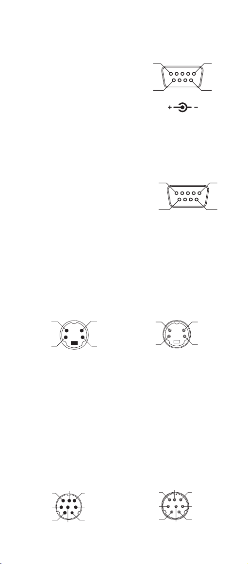
1.5 Pin Assignment
3
1
5
4
2
6
A> Input Port for Mini Decoder
DB 9 Male
Pin No. Wand / CCD /
Slot Reader Laser Scanner
1 N.C. S.O.S.
2 D ATA D ATA
3 N.C. N.C.
4 N.C. N.C.
5 N.C. TRIGGER
6 N.C. P. E.
7 GND GND
8 SHIELD SHIELD
9 +5V +5V
1
5
6
B> Output Port
1. PC Keyboard Output
DIN 5 MALE DIN 5 FEMALE
Pin No. Function Pin No. Function
1 HOST CLK 1 KB CLK
2 HOST DATA 2 KB DATA
4 GND 4 GND
5 Vcc(+5V) 5 Vcc(+5V)
1
4
MiniDIN 6 MALE MiniDIN 6 FEMALE
Pin No. Function Pin No. Function
1 HOST DATA 1 KB DATA
3 GND 3 GND
4 Vcc 4 Vcc
5 HOST CLK 5 KB CLK
5
3
3
5
2
6
4
9
3
5
1
4
2
1
2
6
Page 8
1
2
4
3
6
7
8
5
2
1
3
4
2. RS-232 Output
DB 9 Female
Pin No. Function
2 TXD
3 RXD
5 GND
7 CTS
8 RTS
Power Lead Vcc (+5V)
3. WAND Emulation Output
DB 9 Female
Pin No. Function
2DATA
7 GND
9 Vcc (+5V)
4. ADB Interface
MiniDIN 4 MALE MiniDIN 4 FEMALE
Pin No. Function Pin No. Function
1 ADB 1 ADB
3 Vcc 3 Vcc
4 GND 4 GND
5
9
5
9
1
6
1
6
3
1
5. NEC 9801 Interface
MiniDIN 8 MALE MiniDIN 8 FEMALE
Pin No. Function Pin No. Function
1 RST 1 RST
2 GND 2 GND
3 HOST RDY 3 KB RDY
4 HOST DATA 4 KB DATA
5 RTY 5 RTY
8 +5V 8 +5V
7
6
3
1
4
4
2
8
5
2
7
Page 9

Chapter 2 Configuration - General
2.1 Flow Chart
Configuration
Interface Selection
Input Port Selection
Communication
Parameters
Bar Codes Parameters
MSR Parameters
Misc .Parameters
Abort
Configuration
Parameters
Start
etc.
Save
End
Configuration
Recall
Parameter
Set All
Defaults
8
Page 10

2.2 Loop of Programming
The philosophy of programming parameters has been
shown on the flow chart of 2.1. Basically user should
1. Scan Start of Configuration.
2. Scan all necessary labels for parameters that meet
applications.
3. Scan End of Configuration to end the
programming.
4. To permanently save the settings you
programmed, just scan label for Save Parameters.
5. To go back to the Default Settings, just scan label
for Set All Defaults.
2.3 Factory Default Settings
The factory default settings are shown with < > and
bold in the following sections. You can make your
own settings by following the procedures in this
manual. If you want to save the settings permanently,
you should scan the label of "Save Parameters" in
chapter 2.4, otherwise the settings will not be saved
after the decoder power is off, and all settings will go
back to previous settings.
By scanning "Set All Default" label, the settings will
go back to the factory default settings.
9
Page 11

2.4 Main Page of Configuration
Save Parameters
%$ + / 0
Recall Stored
Parameters
%$ + / 1
Set All Defaults
%$ + / 2
Start Configuration
%$ + / 3
End Configuration
%$ + / 4
Abort Configuration
%$ + / 6
Version Information
%$ + / 5
Save Parameters -
The parameter settings will be saved permanently.
Recall Stored Parameters -
Replace the current parameters by the parameters
you saved last time.
Set All Defaults -
Set all the parameters to the factory default settings.
Abort Configuration -
Terminate current programming status.
Version Information -
Display the decoder version information and date
code.
10
Page 12

Chapter 3 Interface and
Reading Mode Selection
3.1 Interface Selection
<Keyboard Mode>
%0 0 U 0
WAND Emulation
%0 0 M2
USB Mode
%0 X O 8
3.2 Memory Function
<Enable>
RS232 Mode
%0 0 U 8
OCIA Mode
%0 0 M4
%0 X I 2
Disable
%0 X I 0
11
Page 13

3.3 Reading Mode Selection
<Good Read OFF>
%0271
Continuous/Trigger OFF
%0272
Continuous/Auto Power On
%0273
Flash/Auto Power On
%0276
Reserved2
Trigger ON/OFF
%0270
Testing
%0275
Flash
%0274
Reserved1
%0277
%09F8
Reserved4
%09FA
Reserved3
%09F9
Reserved5
%09FB
12
Page 14

Ch.4 Communication Parameters
4.1 RS232 Mode Parameters
A> Set Up BAUD Rate
600
%0 Y 7 0
2400
%0 Y 7 2
<9600>
%0 Y 7 7
38400
%0 Y 7 5
B> Set Up Data Bits
7 Data Bits
%0 Y 8 0
1200
%0 Y 7 1
4800
%0 Y 7 3
19200
%0 Y 7 4
<8 Data Bits>
C> Set Up Stop Bits
<1 Bit>
%0 Y O 8
%0 Y 8 8
2 Bits
%0 Y O 0
13
Page 15

D> Set Up Parity
<None>
%0 Y N 7
Odd
%0 Y N 3
Space
%0 Y N 0
E> Handshaking
RTS/CTS Enable
%0188
ACK/NAK Enable
Even
%0 Y N 2
Mark
%0 Y N 1
<RTS/CTS Disable>
%0180
%0144
XON/XOFF Enable
%0 3 K 4
<ACK/NAK Disable>
%0140
<XON/XOFF Disable>
%0 3 K 0
14
Page 16

4.2 Keyboard Wedge Mode Parameters
A> Terminal Type
<IBM PC/AT, PS/2>
%0ZF0
IBM PS/2 25, 30
%0ZF2
Apple Desktop Bus(ADB)
%0ZF4
IBM 122 Key (1)
%0ZF6
IBM 122 Key (2)
%0ZF8
IBM PC/XT
%0ZF1
NEC 9800
%0ZF3
IBM 5550
%0ZF5
IBM 102 Key
%0ZF7
Reserved 1
Reserved 2
%0ZFA
Reserved 4
%0ZFC
%0ZF9
Reserved 3
%0ZFB
Reserved 5
%0ZFD
15
Page 17

B> Upper/Lower Case
<No Change>
%0330
Upper Case
%0331
Lower Case
%0332
C> Send Character by ALT Method
Enable
%0 3 O 8
<Disable>
%0 3 O 0
D> Select Numerical Pad
ON
%0 1 K 4
<OFF>
%0 1 K 0
16
Page 18

4.3 Output Characters Parameters
A> Select Terminator
<CR+LF>
CR
Space
STX-ETX
%7 S 2 +
None
%7 S 7 +
%7 S 0 +
LF
%7 S 1 +
%7 S 4 +
HT(TAB)
%7 S 3 +
%7 S 5 +
17
Page 19

B> Time-out Between Characters
<0 ms>
10 ms
50 ms
200 ms
%0070
5 ms
%0071
%0072
25 ms
%0073
%0074
100 ms
%0075
%0076
300 ms
18
%0077
Page 20

4.4 Wand Emulation Mode Parameters
A> TTL Level Representation
<Bar Equals High>
%0 2 K 4
Bar Equals Low
B> Scan Speed Selection
<Fast>
%0288
Slow
C> Output Format Selection
<Output as Code 39>
%0 2 O 8
Output as Code 39
Full ASCII
%0 2 K 0
%0280
Output as Original
Code Format
%0XK4
%0 2 O 0
19
Page 21

4.5 OCIA Mode Parameters
<NCR 8 Bit Format>
%0 2 J 0
Spectra-Physics
%0 2 J 2
NCR 9 Bit Format
%0 2 J 1
Nixdorf
%0 2 J 3
20
Page 22

Ch.5 Bar Codes & Others
5.1 Symbologies Selection
UPC-A <ON>
%0 A 4 4
UPC-E <ON>
%0 B O 8
EAN-13/JAN-13 <ON>
%0 A 2 2
EAN-8/JAN-8 <ON>
%0 A 1 1
CODE 39 <ON>
%0 E O 8
OFF
%0 A 4 0
OFF
%0 B O 0
OFF
%0 A 2 0
OFF
%0 A 1 0
OFF
CODE 128 <ON>
%0 F O 8
CODABAR/NW7 <ON>
%0 J O 8
%0 E O 0
OFF
%0 F O 0
OFF
%0 J O 0
21
Page 23

Interleave 25 <ON>
%0 GO8
Industrial 25 ON
%0 H O 8
Matrix 25 ON
%0 I O 8
CODE 93 ON
%0 K O 8
CODE 11 ON
%0 L O 8
OFF
%0 GO0
<OFF>
%0 H O 0
<OFF>
%0 I O 0
<OFF>
%0 K O 0
<OFF>
China Postage ON
%0 MO 8
MSI/PLESSEY ON
%0 N O 8
%0 L O 0
<OFF>
%0 MO 0
<OFF>
%0 N O 0
22
Page 24

BC412 ON
%0 OO8
Code 2 of 6 ON
%0 P O 8
Telepen ON
%0 T O 8
Reserved4 ON
%0 QO8
Reserved5 ON
%0 R O 8
<OFF>
%0 OO0
<OFF>
%0 P O 0
<OFF>
%0 T O 0
<OFF>
%0 QO0
<OFF>
Reserved6 ON
<OFF>
%0 S O 8
Select All Bar Codes
%1 A / +
23
%0 R O 0
%0 S O 0
Page 25

5.2 UPC/EAN/JAN Parameters
A> Reading Type
UPCA=EAN13 ON
%0AK4
UPCA=EAN13<OFF>
ISBN Enable
%0 B 8 8
ISBN <Disable>
ISSN Enable
%0 B 4 4
ISSN <Disable>
Decode with Supplement
%0 1 O 0
<Autodiscriminate
Supplement>
B> Supplementals Set Up
%0AK0
%0 B 8 0
%0 B 4 0
%0 1 O 8
<Not Transmit>
%0 B 3 3
Transmit 5 Code
%0 B 3 2
Transmit 2 Code
%0 B 3 1
Transmit 2&5 Code
%0 B 3 0
24
Page 26

C> Check Digit Transmission
UPC-A Check Digit
Transmission <ON>
%0 A I 2
UPC-E Check Digit
Transmission <ON>
%0 B I 2
EAN-8 Check Digit
Transmission <ON>
%0 A 8 8
EAN-13 Check Digit
Transmission <ON>
%0 A H 1
ISSN Check Digit
Transmission <ON>
OFF
%0 A I 0
OFF
%0 B I 0
OFF
%0 A 8 0
OFF
%0 A H 0
25
OFF
%0
B K 0
%0
B K 4
Page 27

5.3 Code 39 Parameters
A> Type of Code
<Standard>
%0 E H 1
Full ASCII
Italian Pharmacy/Code 32
<OFF>
%0 E 8 0
Italian Pharmacy/
Code 32 ON
B> Check Digit Transmission
<Do Not Calculate
Check Digit>
%0 E M2
Calculate Check Digit
& Not Transmit
Calculate Check Digit
& Transmit
%0 E H 0
%0 E 8 8
%0 E M6
%0 E M4
C> Output Start/Stop Character
Enable
%0 E 4 4
<Disable>
26
%0 E 4 0
Page 28

D> Decode Asterisk
Enable
%0 E 2 2
<Disable>
%0 E 2 0
E> Set Up Code Length
To set the fixed length:
1. Scan the "Begin" label of the desired set.
2. Go to the Decimal Value Tables in Appendix A,
scan label(s) that represents the length to be
read.
3. Scan the "Complete" label of the desired set.
Repeat the steps 1 - 3 to set additional lengths.
<Variable>
%4 E 1 +
Fix Length (2 Sets Available)
1. 1st Set Begin 2. Decimal Value
(Appendix A)
%4 E 0 0
1. 2nd Set Begin 2. Decimal Value
3. 1st Set Complete
%4 E 0 1
(Appendix A)
%4 E 0 0
3. 2nd Set Complete
%4 E 0 2
Minimum Length
1. Begin 2. Decimal Value
(Appendix A)
%2 + - /
3. Complete
%2 C 0 +
27
Page 29

5.4 Code 128 Parameters
A> Check Digit Transmission
Do Not Calculate
Check Digit
%0 F N 1
<Calculate Check Digit
& Not Transmit>
%0 F N 5
B> Append FNC2
ON
%0 F 8 8
Calculate Check
Digit & Transmit
%0 F N 7
<OFF>
%0 F 8 0
C> Set Up Code Length
To set the fixed length:
1. Scan the "Begin" label of the desired set.
2. Go to the Decimal Value Tables in Appendix A,
scan label(s) that represents the length to be
read.
3. Scan the "Complete" label of the desired set.
Repeat the steps 1 - 3 to set additional lengths.
28
Page 30

<Variable>
%4 F 1 +
Fix Length (2 Sets Available)
1. 1st Set Begin 2. Decimal Value
(Appendix A)
%4 F 0 0
3. 1st Set Complete
%4 F 0 1
1. 2nd Set Begin 2. Decimal Value
(Appendix A)
%4 F 0 0
3. 2nd Set Complete
%4 F 0 2
Minimum Length
1. Begin 2. Decimal Value
(Appendix A)
%2 + - /
3. Complete
%2 C 1 +
29
Page 31

5.5 Interleave 25 Parameters
A> Check Digit Transmission
<Do Not Calculate
Check Digit>
%0 G N 3
Calculate Check Digit
& Transmit
Calculate Check Digit
& Not Transmit
%0 G N 5
B> Set Up Number of Character
<Even>
%0 G 8 8
Odd
%0 G N 7
%0 G 8 0
C> Brazilian Banking Code
<Disable>
%0 G 4 0
Enable
30
%0 G 4 4
Page 32

D> Set Up Code Length
To set the fixed length:
1. Scan the "Begin" label of the desired set.
2. Go to the Decimal Value Tables in Appendix A,
scan label(s) that represents the length to be
read.
3. Scan the "Complete" label of the desired set.
Repeat the steps 1 - 3 to set additional lengths.
<Variable>
%4 G 1 +
Fix Length (2 Sets Available)
1. 1st Set Begin 2. Decimal Value
(Appendix A)
%4 G 0 0
3. 1st Set Complete
%4 G 0 1
1. 2nd Set Begin 2. Decimal Value
(Appendix A)
%4 G 0 0
3. 2nd Set Complete
%4 G 0 2
Minimum Length
1. Begin 2. Decimal Value
(Appendix A)
%2 + - /
3. Complete
%2 C 2 +
31
Page 33

5.6 Industrial 25 Parameters
A> Check Digit Transmission
<Do Not Calculate
Check Digit>
%0 HN3
Calculate Check Digit
& Transmit
%0 HN7
Calculate Check Digit
& Not Transmit
%0 HN5
B> Set Up Code Length
To set the fixed length:
1. Scan the "Begin" label of the desired set.
2. Go to the Decimal Value Tables in Appendix A,
scan label(s) that represents the length to be
read.
3. Scan the "Complete" label of the desired set.
Repeat the steps 1 - 3 to set additional lengths.
32
Page 34

<Variable>
%4 H 1 +
Fix Length (2 Sets Available)
1. 1st Set Begin 2. Decimal Value
(Appendix A)
%4 H 0 0
3. 1st Set Complete
%4 H 0 1
1. 2nd Set Begin 2. Decimal Value
(Appendix A)
%4 H 0 0
3. 2nd Set Complete
%4 H 0 2
Minimum Length
1. Begin 2. Decimal Value
(Appendix A)
%2 + - /
3. Complete
%2 C 3 +
33
Page 35

5.7 Matrix 25 Parameters
A> Check Digit Transmission
<Do Not Calculate
Check Digit>
%0 I N 3
Calculate Check Digit
& Transmit
Calculate Check Digit
%0 I N 7
& Not Transmit
%0 I N 5
B> Set Up Code Length
To set the fixed length:
1. Scan the "Begin" label of the desired set.
2. Go to the Decimal Value Tables in Appendix A,
scan label(s) that represents the length to be
read.
3. Scan the "Complete" label of the desired set.
Repeat the steps 1 - 3 to set additional lengths.
34
Page 36

<Variable>
%4 I 1 +
Fix Length (2 Sets Available)
1. 1st Set Begin 2. Decimal Value
(Appendix A)
%4 I 0 0
3. 1st Set Complete
%4 I 0 1
1. 2nd Set Begin 2. Decimal Value
(Appendix A)
%4 I 0 0
3. 2nd Set Complete
%4 I 0 2
Minimum Length
1. Begin 2. Decimal Value
(Appendix A)
%2 + - /
3. Complete
%2 C 4 +
35
Page 37

5.8 CODABAR/NW7 Parameters
A> Set Up Start/Stop Characters Upon
Transmission
ON
<OFF>
%0 J H 1
%0 J H 0
B> Transmission Type of Start/Stop
<A/B/C/D> <Start>
A Start
B Start
C Start
D Start
%0 4 V F
%0 4 V 1
%0 4 V 2
%0 4 V 4
%0 4 V 8
<A/B/C/D> <Stop>
%0 4 F F
A Stop
%0 4 F 1
B Stop
%0 4 F 2
C Stop
%0 4 F 4
D Stop
36
%0 4 F 8
Page 38

C> Set Up Code Length
To set the fixed length:
1. Scan the "Begin" label of the desired set.
2. Go to the Decimal Value Tables in Appendix A,
scan label(s) that represents the length to be
read.
3. Scan the "Complete" label of the desired set.
Repeat the steps 1 - 3 to set additional lengths.
<Variable>
%4 J 1 +
Fix Length (2 Sets Available)
1. 1st Set Begin 2. Decimal Value
(Appendix A)
%4 J 0 0
3. 1st Set Complete
%4 J 0 1
1. 2nd Set Begin 2. Decimal Value
(Appendix A)
%4 J 0 0
3. 2nd Set Complete
%4 J 0 2
Minimum Length
1. Begin 2. Decimal Value
(Appendix A)
%2 + - /
3. Complete
%2 C 5 +
37
Page 39

5.9 Code 93 Parameters
A> Check Digit Transmission
<Calculate Check 2 Digits
& Not Transmit>
%0 K N 4
Do Not Calculate
Check Digit
%0 K N 3
B> Set Up Code Length
To set the fixed length:
1. Scan the "Begin" label of the desired set.
2. Go to the Decimal Value Tables in Appendix A,
scan label(s) that represents the length to be
read.
3. Scan the "Complete" label of the desired set.
Repeat the steps 1 - 3 to set additional lengths.
38
Page 40

<Variable>
%4 K 1 +
Fix Length (2 Sets Available)
1. 1st Set Begin 2. Decimal Value
(Appendix A)
%4 K 0 0
3. 1st Set Complete
%4 K 0 1
1. 2nd Set Begin 2. Decimal Value
(Appendix A)
%4 K 0 0
3. 2nd Set Complete
%4 K 0 2
Minimum Length
1. Begin 2. Decimal Value
(Appendix A)
%2 + - /
3. Complete
%2 C 6 +
39
Page 41

5.10 Code 11 Parameters
A> Check Digit Transmission
<Do Not Calculate
Check Digit>
%0 L N 3
Calculate Check 1
Digit & Transmit
Calculate Check 1 Digit
%0 L N 7
& Not Transmit
%0 L N 5
Calculate Check 2 Digits
Calculate Check 2
Digits & Transmit
%0 L N 6
& Not Transmit
%0 L N 4
B> Set Up Code Length
To set the fixed length:
1. Scan the "Begin" label of the desired set.
2. Go to the Decimal Value Tables in Appendix A,
scan label(s) that represents the length to be
read.
3. Scan the "Complete" label of the desired set.
Repeat the steps 1 - 3 to set additional lengths.
40
Page 42

<Variable>
%4L1+
Fix Length (2 Sets Available)
1. 1st Set Begin 2. Decimal Value
(Appendix A)
%4L00
3. 1st Set Complete
%4L01
1. 2nd Set Begin 2. Decimal Value
(Appendix A)
%4L00
3. 2nd Set Complete
%4L02
Minimum Length
1. Begin 2. Decimal Value
(Appendix A)
%2 + - /
3. Complete
%2 C 7 +
41
Page 43

5.11 MSI/PLESSEY Code Parameters
A> Check Digit Transmission
<Do Not Calculate
Check Digit>
%0 NN3
Calculate Check Digit
& Transmit
Calculate Check Digit
%0 NN7
& Not Transmit
%0 NN5
B> Set Up Code Length
To set the fixed length:
1. Scan the "Begin" label of the desired set.
2. Go to the Decimal Value Tables in Appendix A,
scan label(s) that represents the length to be
read.
3. Scan the "Complete" label of the desired set.
Repeat the steps 1 - 3 to set additional lengths.
42
Page 44

<Variable>
%4 N 1 +
Fix Length (2 Sets Available)
1. 1st Set Begin 2. Decimal Value
(Appendix A)
%4 N 0 0
3. 1st Set Complete
%4 N 0 1
1. 2nd Set Begin 2. Decimal Value
(Appendix A)
%4 N 0 0
3. 2nd Set Complete
%4 N 0 2
Minimum Length
1. Begin 2. Decimal Value
(Appendix A)
%2 + - /
3. Complete
%2 C 9 +
43
Page 45

5.12 BC 412 Code Parameters
A> Check Digit Transmission
Do Not Calculate
Check Digit
%0 O N 3
<Calculate Check
Digit & Transmit>
Calculate Check Digit
%0 O N 7
& Not Transmit
%0 O N 5
B> Set Up Code Length
To set the fixed length:
1. Scan the "Begin" label of the desired set.
2. Go to the Decimal Value Tables in Appendix A,
scan label(s) that represents the length to be
read.
3. Scan the "Complete" label of the desired set.
Repeat the steps 1 - 3 to set additional lengths.
44
Page 46

<Variable>
%4 O 1 +
Fix Length (2 Sets Available)
1. 1st Set Begin 2. Decimal Value
(Appendix A)
%4 O 0 0
3. 1st Set Complete
%4 O 0 1
1. 2nd Set Begin 2. Decimal Value
(Appendix A)
%4 O 0 0
3. 2nd Set Complete
%4 O 0 2
Minimum Length
1. Begin 2. Decimal Value
(Appendix A)
%2 + - /
3. Complete
%2 C A +
45
Page 47

5.13 Code 2 of 6 Parameters
A> Check Digit Transmission
Do Not Calculate
Check Digit
%0 P N 3
<Calculate Check
Digit & Transmit>
Calculate Check Digit
%0 P N 7
& Not Transmit
%0 P N 5
B> Set Up Code Length
To set the fixed length:
1. Scan the "Begin" label of the desired set.
2. Go to the Decimal Value Tables in Appendix A,
scan label(s) that represents the length to be
read.
3. Scan the "Complete" label of the desired set.
Repeat the steps 1 - 3 to set additional lengths.
46
Page 48

<Variable>
%4 P 1 +
Fix Length (2 Sets Available)
1. 1st Set Begin 2. Decimal Value
(Appendix A)
%4 P 0 0
3. 1st Set Complete
%4 P 0 1
1. 2nd Set Begin 2. Decimal Value
(Appendix A)
%4 P 0 0
3. 2nd Set Complete
%4 P 0 2
Minimum Length
1. Begin 2. Decimal Value
(Appendix A)
%2 + - /
3. Complete
%2 C B +
47
Page 49

5.14 Telepen Parameters
A> Type of Code
<Telepen ASCII>
%0 T 8 0
Telepen Numeric
B> Check Digit Transmission
Do Not Calculate
Check Digit
%0 T N 3
<Calculate Check Digit
& Not Transmit>
%0 T N 5
Calculate Check
Digit & Transmit
%0 T 8 8
%0 T N 7
C> Set Up Code Length
To set the fixed length:
1. Scan the "Begin" label of the desired set.
2. Go to the Decimal Value Tables in Appendix A,
scan label(s) that represents the length to be
read.
3. Scan the "Complete" label of the desired set.
Repeat the steps 1 - 3 to set additional lengths.
48
Page 50

<Variable>
%4 T 1 +
Fix Length (2 Sets Available)
1. 1st Set Begin 2. Decimal Value
(Appendix A)
%4 T 0 0
3. 1st Set Complete
%4 T 0 1
1. 2nd Set Begin 2. Decimal Value
(Appendix A)
%4 T 0 0
3. 2nd Set Complete
%4 T 0 2
Minimum Length
1. Begin 2. Decimal Value
(Appendix A)
%2 + - /
3. Complete
%2 C F +
49
Page 51

Ch.6 Miscellaneous Parameters
6.1 Language Selection
<US English>
Italian
French
Swedish
%0 Z V 0
UK English
%0 Z V 1
%0 Z V 2
Spanish
%0 Z V 3
%0 Z V 4
German
%0 Z V 5
%0 Z V 6
Switzerland
Hungarian
%0 Z V 8
%0 Z V 7
Japanese
%0 Z V 9
50
Page 52

Belgium
Denmark
Turkey
%0 Z V A
Portuguese
%0 Z V B
%0 Z V C
Netherlands
%0 Z V D
%0 Z V E
Reserved1
%0 Z V F
51
Page 53

6.2 Bar Code ID
ON
%0 0 H 1
<OFF>
%0 0 H 0
Default
%913+
With this function ON, a leading character will be
added to the output string while scanning code, user
may refer to the following table to know what kind of
bar code is being scanned.
Please refer to the table below for matching code ID
of codes read in.
Code Type ID Code Type ID
UPC-A A UPC-E B
EAN-8 C EAN-13 D
CODE 39 E CODE 128 F
Interleave 25 G Industrial 25 H
Matrix 25 I Codabar/NW7 J
CODE 93 K CODE 11 L
China Postage M MSI/PLESSEY N
BC412 O Code 2 of 6 P
Telepen T
User Define Code ID
To set the code ID:
1. Scan the symbologies label.
2. Go to the ASCII Tables in Appendix B, scan label
that represents the desired code ID.
Note:
User define code ID will override default value.
Program will not check the conflict. It is possible
to have more than two symbologies which have
same code ID.
52
Page 54

UPC-A
%9 1 A +
EAN-13/JAN-13
%9 1 Y +
CODE 39
%9 1 E +
CODABAR/NW7
%9 1 J +
Industrial 25
%9 1 H +
UPC-E
%9 1 B +
EAN-8/JAN-8
%9 1 Z +
CODE 128
%9 1 F +
Interleave 25
%9 1 G +
Matrix 25
CODE 93
%9 1 K +
China Postage
%9 1 M+
BC412
%9 1 O +
%9 1 I +
CODE 11
%91L+
MSI/PLESSEY
%9 1 N +
53
Page 55

Code 2 of 6
%9 1 P +
Reserved4
%9 1 Q +
Reserved6
%9 1 S +
Telepen
%91T+
Reserved5
%9 1 R +
54
Page 56

6.3 Reading Level
Bar Equals High
%0 3 I 2
6.4 Accuracy
<1 Time>
%0130
3 Times
%0132
6.5 Buzzer Beep Tone
<Bar Equals Low>
%0 3 I 0
2 Times
%0131
4 Times
%0133
<High>
Low
%0 1 J 3
%0 1 J 1
Medium
%0 1 J 2
Off
%0 1 J 0
55
Page 57

6.6 Sensitivity of Continuous Reading
Mode
<Fast>
%0388
Slow
6.7 Notebook Function
Enable
%0344
<Disable>
6.8 Reverse Output Characters
<Disable>
%0380
%0340
%0 3 H 0
Enable
%0 3 H 1
56
Page 58

6.9 Setup Deletion
To setup the deletion of output characters:
1. Scan the label of the desired set below.
2. Scan the label of the desired symbology.
3. Go to the Decimal Value Tables in Appendix A, scan
label(s) that represents the desired position to be
deleted.
4. Scan the "Complete" label of "Character Position
to be Deleted".
5. Go to the Decimal Value Tables in Appendix A, scan
label(s) that represents the number of characters
to be deleted.
6. Scan the "Complete" label of "Number of
Characters to be Deleted".
Repeat the steps 1 - 6 to set additional deletion.
A> Select Deletion Set Number
1. 1st Set
3. 3rd Set
5. 5th Set
%800+
%802+
%804+
2. 2nd Set
%801+
4. 4th Set
%803+
6. 6th Set
%805+
57
Page 59

B> Symbologies Selection
UPC-A
%8 1 A +
EAN-13/JAN-13
%8 1 Y +
CODE 39
%8 1 E +
CODABAR/NW7
%8 1 J +
Industrial 25
%8 1 H +
UPC-E
%8 1 B +
EAN-8/JAN-8
%8 1 Z +
CODE 128
%8 1 F +
Interleave 25
%8 1 G +
Matrix 25
CODE 93
%8 1 K +
China Postage
%8 1 M+
%8 1 I +
CODE 11
%81L+
MSI/PLESSEY
%8 1 N +
58
Page 60

BC412
%8 1 O +
Telepen
%81T+
Resvered5
%8 1 R +
All Codes
%8 1 S +
None
%814+
Code 2 of 6
%8 1 P +
Resvered4
%8 1 Q +
C> Character Position to be Deleted
1. Decimal Value
(Appendix A) 2. Complete
%820+
D>
Number of Characters to be Deleted
1. Decimal Value
(Appendix A) 2. Complete
%830+
59
Page 61

6.10 Setup Insertion
To setup the insertion of output characters:
1. Scan the label of the desired set.
2. Scan the label of the desired symbology.
3. Go to the Decimal Value Tables in Appendix A, scan
label(s) that represents the desired position to be
inserted.
4. Scan the "Complete" label of "Character Position
to be Inserted".
5. Go to the ASCII Tables in Appendix B or Function
Key Tables in Appendix C, scan label(s) that
represents the desired characters to be inserted.
6. Scan the "Complete" label of "Characters to be
Inserted".
Repeat the steps 1 - 6 to set additional insertion.
A> Select Insertion Set Number
1. 1st Set
3. 3rd Set
5. 5th Set
%500+
%502+
%504+
2. 2nd Set
%501+
4. 4th Set
%503+
6. 6th Set
%505+
60
Page 62

B> Symbologies Selection
UPC-A
%5 1 A +
EAN-13/JAN-13
%5 1 Y +
CODE 39
%5 1 E +
CODABAR/NW7
%5 1 J +
Industrial 25
%5 1 H +
UPC-E
%5 1 B +
EAN-8/JAN-8
%5 1 Z +
CODE 128
%5 1 F +
Interleave 25
%5 1 G +
Matrix 25
CODE 93
%5 1 K +
China Postage
%5 1 M+
%5 1 I +
CODE 11
%51L+
MSI/PLESSEY
%5 1 N +
61
Page 63

BC412
%5 1 O +
Telepen
%51T+
Resvered5
%5 1 R +
All Codes
%5 1 S +
None
%514+
Code 2 of 6
%5 1 P +
Resvered4
%5 1 Q +
C> Character Position to be Inserted
1. Decimal Value
(Appendix A) 2. Complete
%520+
D>
Characters to be Inserted
1. ASCII Table
(Appendix B) 2. Complete
%530+
62
Page 64

6.11 Setup IR Sensor
<Disable>
Enable
%0 X H 0
%0 X H 1
63
Page 65

Appendix A Decimal Value Table
0
1
2
3
4
5
6
64
7
8
9
Page 66

Appendix B ASCII Table
NULL SOH
00
ETX EOT
03
ACK BEL
06
HT LF
09
FF CR
0C
SI DLE
0F
DC2 DC3
12
NAK SYN
STX
02
ENQ
05
BS
08
VT
0B
SO
0E
DC1
11
DC4
14
01
04
07
0A
0D
10
13
15
CAN EM
18
ESC FS
1B
RS US
1E
ETB
17
SUB
1A
GS
1D
65
16
19
1C
1F
Page 67

SPACE !
20 21
23 24
26 27
29 2A
2C 2D
2F 30
32 33
"
22
%
25
(
28
+
2B
.
2E
1
31
4
34
35 36
38 39
3B 3C
3E 3F
7
37
:
3A
=
3D
66
Page 68

40
B
42
41
43
46
49
4C
4F
52
55
E
H
K
N
Q
T
W
44
45
47
48
4A
4B
4D
4E
50
51
53
54
56
57
58
5B
5E
Z
5A
]
5D
59
5C
5F
67
Page 69

60 61
b
62
63 64
66 67
69 6A
6C 6D
6F 70
72 73
75 76
e
65
h
68
k
6B
n
6E
q
71
t
74
w
77
78 79
7B 7C
7E 7F
z
7A
}
7D
DEL
68
Page 70

Appendix C Function Key Table
F1 F2
C0
F3
C2
F4 F5
C3
F6
C5
F7 F8
C6
F9
C8
F10 F11
C9
F12
CB
Insert Delete
CC
Home
C1
C4
C7
CA
CD
Page Up Page Down
CE
CF
D0
End
Left Right
D1
D2
D3
Up
Down
D4
D5
69
Page 71

Save Parameters
Recall Stored
Parameters
Set All Defaults
Start Configuration
End Configuration
Abort Configuration
Version Inf
ormation
%$ + / 0
%$ + / 1
%$ + / 2
%$ + / 3
%$ + / 4
%$ + / 6
%$ + / 5
Ver 3.5
 Loading...