

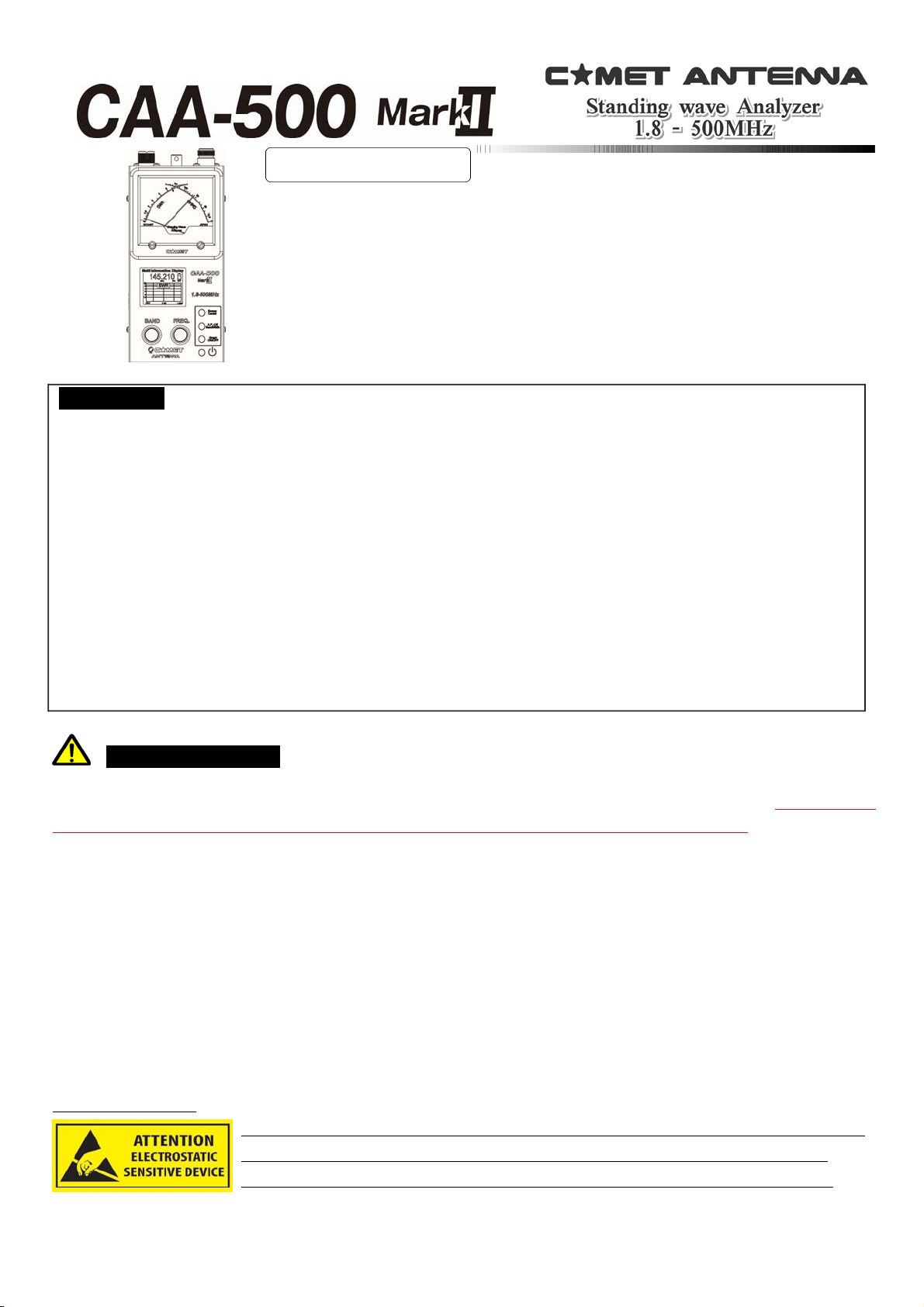
Instruction Manual
Thank you for your purchase of this instrument. It was built under tight quality control
standards and procedures; however, there is always the possibility of damage during
shipping. Should this occur, please notify the dealer from whom you purchased it
immediately so they can in itiate the damag e claim p roces s with the shipping company.
Please read this manual completely before beginning operation, so as to understand its
features and capabilities fully.
◆
Features
●
Built‐in broadband high ‐stability transmitter for easy measurement of resonant frequency, SWR, and impedance.
●
Color LCD & cross‐needle meter display provide SWR and Impedance information simultaneously.
●
Separate ham band segments can be swept to display the SWR characteristics in the graph automatically.
Moreover, it is possible to plot the SWR characteristics manually with user‐defined center frequency and sweep
bandwidth.
●
Size AA alkaline (manganese) or Ni‐MH rechargeable batteries (six required) may be used. Typical battery life is 9
hours of continuous operation when using AA cells.
●
External 8‐16V DC power may be used to power the meter; this allows trickle charging of Ni‐MH cells.
●
The programmable Auto Power Off func tion preserves batte ry capacity in cas e you forget to turn the meter
off.
●
A hand strap post is provided, for ease of use and to minimize the chance of dropping the CA‐500 MarkII.
Important Cautions
◆
This is a delicate measuring instrument; please take care not to drop it or subject it to physical shock.
◆
The impedance bridge of this instrument is immediately inside the antenna connection point. Be absolutely
certain not to apply power from an external transmitter, as this will damage the CAA‐500 MarkII.
◆
Strong local RF fields (in a multi‐station environment, for example) may cause unstable SWR readings.
◆
When not using Ni‐MH batteries, always turn OFF the Charge switch on the battery case. Failure to do so may
result in battery rupture, leakage and/or explosion if you apply charging voltage to alkaline cells.
◆
The external DC supply voltage must be between 8V to 16V, and the current supplied must be at least 250mA.
Never apply DC voltages greater than 16V, nor AC voltage of any kind. Our warranty does not cover damage
caused by the use of an improper power source.
◆
When using AA batteries, the LCD display will become unstable when the batteries are weak. Change Batteries
as soon as the display starts blinking, and change all batteries to improve the battery shelf life.
Remove the batteries when not in use for extended periods of time to avoid damage caused by leakage.
▼
Before using
◆
To avoid ESD damage, it is important to discharge any static electricity that
may have accumulated on the antenna system by touching grounding the
antenna’s coax cable connector before screwing it onto the SWR analyzer.
P.1
◆
Panel/Case Parts and Descriptions
①
Display Meter This Cross Meter displays both SWR and Impedance simultaneously.
②
Multi‐function Display The color LCD (Liquid Crystal Display) shows frequency, amateur band, and SWR data
(impedance (Z)/resistance (R)/reactance (X)), and also can provide a swept‐frequency SWR graph.
③
BAND Knob This knob is used to select the frequency band within the range 1.8 to 500 M Hz. Clockwise rotation of
this knob selects a higher frequency band. It is also used for setting of the APO (Automatic Power Off) function.
④
FREQ.Knob This knob is used to set the frequen cy within the selected amateur band. Clockwise rotation increases
the frequency, while counter‐clockwise rotation lowers the frequency.
⑤
SWEEP/CENTER Button In the “Normal” mode, pressing this button starts an SWR sweep of the band.
・
When in the SWR Graph mode, pressing this button sets the current display frequency to be the center frequency of
the graph. In this mode, rotate the (3)BAND knob to adjust the Sweep width; press the (6) A.P.OFF/WIDTH button to
confirm. Now rotate the (4) FREQ knob to create and display the SWR plot.
⑥
A.P.‐OFF/BANDWIDTH Button In the “Normal” mode, press and hold in this button for three seconds to allow setting
of the Auto Power Off feature’s time interval.・In the “Manual” plot mode, pressing this button allows you to set the
bandwidth of the SWR Sweep.・While in the “Manual” plot mode, pressing this button allows you to change the color
of the SWR Graph.
⑦
GRAPH ON/OFF Button Press this button to switch between the “Normal” mode and the SWR Graph modes.
⑧
POWERButton This is the main Power On/Off button for this device. Press once to turn the unit on, and again to
turn it off.
⑨
RF Connectors These are the coaxial jacks used for connection to the coaxial cable. T he left connector is an “M”
(“UHF”) type (used for 1.8‐300 MHz), while the right jack is Type N, used for 300‐500 MHz. Switching is automatic,
based on the Band setting.
⑩
Hand Strap Mounting Bracket You may connect a commercially‐available hand strap here. As the diameter of the
mounting hole is greater than 1 mm, a sturdy strap (highly recommended) may be attached.
⑪
External DC Power Terminal External DC (8‐16V) may be connected here. The center pin is positive (+).
⑫
Battery Case This is the housing for six AA cells. Please install them according to the inscription inside the case.
⑬
Charge Switch (Inside Battery Case) This is the switch for enabling/disabling trickle charging of Ni‐MH cells, if u sed.
When using Alkaline or similar batteries, be sure to set this switch to the OFF position. In the event of
battery leakage, serious damage to this unit may occur if the switch is set to ON during use.
(※) Trickle charging is useful to help maintain a full charge on your battery by compensating for the slight
self‐discharge that can occur even without a load being placed on the batteries
Before You Start
This instrument has been calibrated with the unit being held horiz ontally, with the meter facing up. The discussion
below is an operating example; the parameters you set may affect the actual results.
P.2

Always be sur e that you connect your coaxial connector to the proper connector. If you are connected to the
opposite connector, measurements will be impossible and if the wrong connector is used, da mage to the jack
may occur.
▲
OPERATION
It is helpful to review operation before commencing operation. Steps (1) and (3) may be omitted once you have
verified that the unit is operating properly.
①
Connect a 50‐Ohm dummy load (not supplied) to the “M” (“UHF”) jack.
②
Press the POWER switch to turn the unit on in the Normal mode.
Normal Mode Display Screen
Frequency Battery Status
Band Scale
The amateur bands 1.8‐430 MHz are shown with a blue
band (※1). Red underscore shows current band.
“U”appearstoleftofBatteryiconwhenonUHF.
SWR Scale and Bar
The SWR is displayed graphically and numerically
here. The SWR is show n to two decimal places.
OHMS Scale and Bar
The resistive component of the impedance is shown both
on the bar graph and numerically. Impedance (R, X) is
also displayed numerically. Above 190 MHz, R/X do not appear.
※
1 Note that not all the annotated amateur radio bands are available in all countries.
※
2. If using Nickel‐Metal Hydride batteries, the battery status meter may never show “Full.” You should recharge
the batteries once the Yellow indication appears. If using alkaline cells, replace when the Yellow indicator appears.
③
When connected to a 50‐Ohm dummy load, the SWR indication should be 1.1 or less. If so, the meter is
performing correctly.
④
Perform measurements according to the discussion below.
Battery Level Meter (※2,3)
Full charge CcCharge
Nearly full
Battery low
Battery level
Critically low
▼
SWR Measurement
●
Connect the coaxial cable to the meter; use the shortest possible cable between the antenna and meter, as any
cable between the antenna and meter can transform the measured impedance, and feedline loss can also cause the
displayed SWR to be better than it actually is. See FAQ later.
●
Set the BAND and FREQ knobs to the band and frequency to be tested on the antenna.
●
You may now read the SWR and resistive value of impedance (OHMS) on the display. If there is a subtle
difference between the mechanical and the LCD, the precision of the mechanical meter has priority.
About the Reactance Display
The display of impedance on the LCD includes both resistive (R) and reactance (X) indications. Note that the X
display is absolute value, so the polarity (+ or ‐) cannot be viewed. Because of diminished accuracy, the numerical
R and X displays do not appear above 190 MHz (but the impedance bar graph remains operational).
▼
Measurement of Antenna Resonant Frequency
■
Connect the antenna to the appropriate antenna connector on the meter, using the shortest possible cable. If you
use a long cable, the m easurement will also include the effects of feedline loss, and impedance differences between
the antenna system and coaxial cable will not show the actual antenna impedance.
■
While w atching the frequency display, rotate the FREQ knob while observing SWR. If you rotate the FREQ knob to
the point where the frequency no longer changes, change the Band to set a new range.
■
The frequency at which the minimum SWR is observed is the resonant frequency for the system.
P.3
 Loading...