

Page 1

www.cometsystem.cz
Instruction Manual
T8348 programmable indoor transmitter
of temperature and CO2 concentration
with RS232 serial output
T8448 programmable indoor transmitter
of temperature and CO2 concentration
with RS485 serial output
Page 2

2 IE-SNC-T83(4)48-03
© Copyright: COMET System, Ltd.
It is prohibited to copy and make any changes in this manual, without
explicit agreement of company COMET System, Ltd. All rights reserved.
COMET System, Ltd. makes constant development and improvement of
their products. Manufacturer reserves the right to make technical changes
to the device without previous notice. Misprints reserved.
Manufacturer is not responsible for damages caused by using the device in
conflict with this manual.
To damages caused by using the device in conflict with this manual can not
be provide free repairs during the warranty period.
Read carefully instruction manual before the first device connection.
Page 3

IE-SNC-T83(4)48-03 3
Table of contents
GENERAL DESCRIPTION ......................................................................... 4
DEVICE SETTING FROM THE MANUFACTURER .................................... 6
DEVICE INSTALLATION ........................................................................... 7
INFO MODE ............................................................................................... 9
DESCRIPTION OF COMMUNICATION PROTOCOLS ............................ 10
MODBUS RTU .........................................................................................10
PROTOCOL COMPATIBLE WITH ADVANTECH-ADAM STANDARD ...12
ARION COMMUNICATION PROTOCOL - AMIT COMPANY .................13
TROUBLESHOOTING ............................................................................. 14
ERROR STATES OF THE DEVICE .........................................................14
TECHNICAL SUPPORT AND SERVICE .................................................14
TECHNICAL DATA .................................................................................. 15
MEASURED VALUES ..............................................................................15
GENERAL SPECIFICATIONS .................................................................15
OPERATING CONDITIONS ....................................................................16
END OF OPERATION .............................................................................16
DIMENSIONS ...........................................................................................17
TYPICAL APPLICATION WIRING ...........................................................17
APPENDIX A ............................................................................................ 18
Page 4
4 IE-SNC-T83(4)48-03
General description
The transmitters are designed for online measurement of carbon dioxide
concentration and temperature of air in a building interiors.
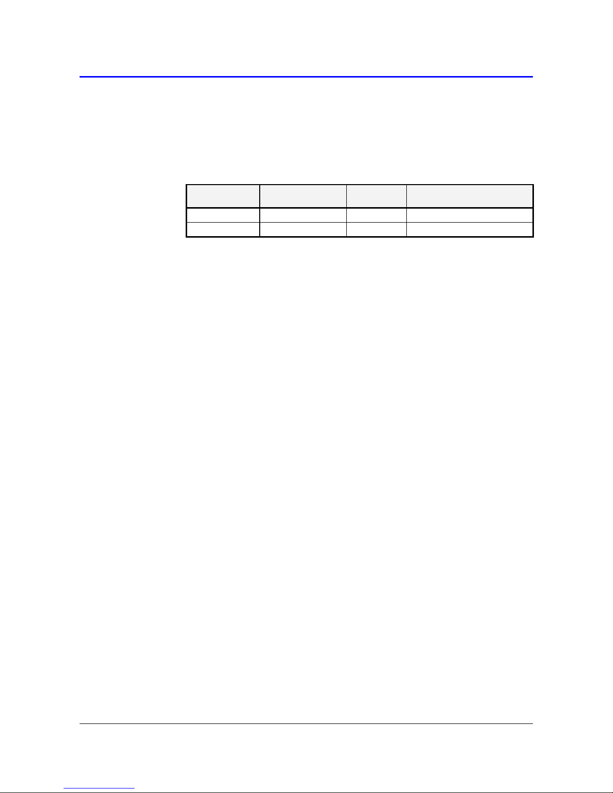
device type
construction type
output
galvanic isolated output
T8348
ambient air
RS232
no
T8448
ambient air
RS485
yes
The CO2 concentration is measured using the dual wavelength NDIR
sensor with multiple point adjustment. The dual wavelength NDIR CO2
sensing procedure compensates aging of the sensing element and offers
maintenance free operation and outstanding long term stability. Measured
values can be read in „SLOW mode“ (filtered, averaged) or in „FAST
mode“ (current values without averaging). SLOW mode has advantages in
applications like climate control because of filtering short time peaks. As an
example exhaled air from an employee passing the sensor could affect the
climate control negatively with a short response time because the control
would trigger a change of the ventilation based on this one-time
measurement. On the contrary in „FAST mode“ no software filter is used
for calculating the output value. This fact adds a noise of typ. ±30ppm
which has to be considered in terms of accuracy. The measured value of
CO2 concentration depends on the value of air pressure, (the altitude at the
place of installation). For this reason, it is suitable for accurate
measurement to set the altitude of the installation site by TSensor software
- see below.
Measured values are displayed on dual line LCD display. The visual
indication of CO2 concentration is provided by three-color LED.
After power up of the device starts internal test. During this time (about
20s) LCD display shows (----) instead of CO2 concentration value.
Supported communication protocols are Modbus RTU, protocol compatible
with standard Advantech-ADAM and protocol ARION. Devices are preset
from manufacturer to Modbus RTU communication protocol. If you would
like to use different communication protocol then Modbus RTU, it is
necessary preset them throw user’s software – see below.
Page 5

IE-SNC-T83(4)48-03 5
Use software Tsensor for setting of all device parameters (recommended).
It is free to download at www.cometsystem.cz. It supports make the
adjustment of the device too. This procedure is described at file
„Calibration manual.pdf“ which is installed commonly with the software.
Change of some parameters is possible to do without user’s software with
Windows hyperterminal (change of communication protocol, its
parameters, LCD display setting). It is described in file “Description of
communication protocols” ( free to download at www.cometsystem.cz ).
Models marked TxxxxZ are non-standard versions of the transmitters.
Description is not included in this manual.
Page 6

6 IE-SNC-T83(4)48-03
Device setting from the manufacturer
If special setting was not required in the order device is set from the
manufacturer to the following parameters:
communication protocol: Modbus RTU
device address: 1
communication speed: 9600Bd, without parity, 2 stop bits
display: switched ON
value displayed at higher line: CO2 concentration
value displayed at lower line: temperature
temperature unit: °C
measurement CO2 mode: “SLOW“
LED indication: up to 1000 ppm lights green LED, between
1000 and 1200 ppm lights yellow LED and
over 1200 ppm lights red LED
altitude: 300 m above see level at the installation site
Page 7

IE-SNC-T83(4)48-03 7
Device installation
Devices are designed for indoor applications. It is recommended to mount
them on universal wiring box (common installation box KU68) with using
two enclosed mounting screws. For correct function there is necessary to
find proper device place. It shouldn’t be placed at places where it can be
affected by sunshine, near radiators, heating elements and other heat
sources, air handlers, windows, doors, into racks and shelves and similar
places. For buildings with less thermal insulation there is not suitable to
place them on external walls of building. If there are communication
conductors placed into conduit, there is strongly recommended make it
caulk, to restrict air flow around device.
For devices with RS485 output there is recommended to use shielded
twisted copper cable, maximal length 1200m. The cable must be located at
indoor rooms. Connect cables to terminals with respecting the signal
polarity. Terminals are self-clamping and can be opened by a suitable
screwdriver (for the opening, insert the screwdriver to upper terminal hole
and lever by him). Nominal cable impedance should be 100 Ω, loop
resistance max. 240 Ω, cable capacity max. 65 pF/m. Suitable cable is e.g.
SYKFY 2x2x0.5 mm2, where one wire pair serves for device powering and
the other pair for communication link. The cable should be led in one line,
i.e. not to „tree“ or „star“. Termination resistor should be located at the end.
For short distance other topology is allowed. Terminate the network by a
termination resistor. The value of the resistor is recommended about
120 Ω. For short distance termination resistor can be left out.
The devices with RS232 interface can be powered from external power
source only. Maximal communication cable length is restricted to 15 m
The cables should not be led in parallel along power cabling. Safety
distance is up to 0.5 m, otherwise undesirable induction of interference
signals can appear.
Firstly mount the rear part of the device on the wiring box with two screws
and connect cables to terminals. Finish the installation by inserting the front
part of the unit.
Electrical system (wiring) may do only worker with required
qualification by rules in operation.
Page 8

8 IE-SNC-T83(4)48-03
Device demounting
If there is necessary demount the device, insert flat bladed screwdriver
max. 3.5 mm wide from top side into middle device’s air hole. There is
fastening member placed, insert screwdriver beyond the fastening member
about 2 cm deep. Then slightly move screwdriver in arrow direction, it
unlock fastening member and the device is partially opened. Remove the
screwdriver and take front part of device at top.Pull front part with
pendulum motion and remove front cover. If there is necessary remove
rear part of the device, please disconnect cables and unscrew two holding
screws.
Page 9

IE-SNC-T83(4)48-03 9
Info mode
If in doubt of setting of installed device, verification of its address is
enabled even without using computer. Power supply should be connected
and jumper should be opened. Jumper is accessible after removing the
front part of device (jumper is placed at the right bottom corner at the same
side as button). Shortly press button behind small
hole on the left side of the device using thin
instrument (for example paper clip). Actual adjusted
address of the device is displayed on LCD display at
decimal base. Next press of button exits info mode
and actual measured values are displayed. Devices
with RS232 interface have address always set to
one. No measurement and communication is
possible during info mode. If device stays in info
mode for longer than 15 s, device automatically
returns to measuring cycle.
Page 10

10 IE-SNC-T83(4)48-03
Description of communication protocols
Detailed description of each communication protocols including examples
of communication is available in individual document “Description of
communication protocols” which is available at www.cometsystem.cz (see
appropriate transmitter pages).
Note: After switching on the power of the device it can last up to 2 s
before the device starts to communicate and measure!
Modbus RTU
Control units communicate on master-slave principle in half-duplex
operation. Only master can send request and only addressed device
responds. During sending of request no other slave station should respond.
During communication, data transfer proceeds in binary format. Each Byte
is sent as eight bit data word in format: 1 start bit, data word 8 bit (LSB
first), 2 stop bits (device sends two stop bits, for receive one stop bit is
enough), without parity. Device supports communication speed from 110Bd
to 115200Bd.
Sent request and response have syntax:
ADDRESS OF DEVICE – FUNCTION – Modbus CRC
Supported function
03 (0x03): Reading of 16-bit registers (Read Holding Registers)
04 (0x04): Reading of 16-bit input gates (Read Input Registers)
16 (0x10): Setting of more 16-bit registers (Write Multiple Registers)
Jumper and button
If communication protocol Modbus is selected the function of jumper and
button is as follows:
Jumper opened – device memory is protected from writing, from device
side it is only enabled to read measured value, writing to memory is
disabled (no change of device address, communication speed and LCD
setting is enabled …)
Page 11

IE-SNC-T83(4)48-03 11
Jumper closed – writing to device memory is enabled by means of
User’s software
Jumper opened and button shortly pressed – device goes to Info mode,
see chapter „Info mode“
Jumper closed and button pressed for longer than six seconds – causes
restoring of manufacturer setting of communication protocol, i.e. sets
Modbus RTU communication protocol, device address sets to 1 and
communication speed to 9600Bd (after button press there is “dEF”
message blinking at LCD display. Six seconds later message “dEF”
stays shown, it means manufacturer setting of communication protocol
is done).
Modbus registry snímače
Variable
Unit
Address
[hex]
X
Address
[dec]
X
Format
Size
Status
Measured temperature
[°C][°F]*
0x0031
49
Int*10
BIN16
R
CO2 concentration
displayed on LCD
ppm
0x0034
52
Int
BIN16
R
CO2 concentration
„FAST“ mode
ppm
0x0054
84
Int
BIN16
R
CO2 concentration
„SLOW“ mode
ppm
0x0055
85
Int
BIN16
R
Serial number of device
Hi
[-]
0x1035
4149
BCD
BIN16
R
Serial number of device
Lo
[-]
0x1036
4150
BCD
BIN16
R
Address of device
[-]
0x2001
8193
Int
BIN16
R/W*
Code of communication
speed
[-]
0x2002
8194
Int
BIN16
R/W*
Version of Firmware Hi
[-]
0x3001
12289
BCD
BIN16
R
Version of Firmware Lo
[-]
0x3002
12290
BCD
BIN16
R
Explanation:
* depends on device setting (by User’s software)
Int*10 register is in format integer*10
R register is designed only for reading
Page 12

12 IE-SNC-T83(4)48-03
W* register is designed for writing, for details see description of
communication protocols
X
register addresses are indexed from zero – register 0x31 is
physically sent as value 0x30, 0x32 as 0x31 (zero based
addressing).
Note: In case there is a need for reading of measured values from the
device with higher resolution than one decimal, measured values
in device are stored also in „Float“ format, which is not directly
compatible with IEEE754.
Protocol compatible with Advantech-ADAM standard
Control units communicate on master-slave principle in half-duplex
operation. Only master can send requests and only addressed device
responds. During sending request any of slave devices should respond.
During communication data is transferred in ASCII format (in characters).
Each Byte is sent as two ASCII characters. Device supports
communication speed from 1200Bd to 115200Bd, parameters of
communication link are 1 start bit + eight bit data word (LSB first) + 1 stop
bit, without parity.
Jumper
Jumper is located next to connection terminals. If communication protocol
compatible with standard Advantech-ADAM is selected, its function is the
following:
If jumper during switching ON the power is closed, device always
communicates with following parameters regardless stored setting in
the device: communication speed 9600 Bd, without check sum, device
address 0.
If jumper is closed during device operation, device temporarily changes
its address to 0, it will communicate in the same communication speed
as before closing jumper and will communicate without check sum. After
jumper is opened setting of address and check sum is reset in
accordance with values stored in the device.
Page 13

IE-SNC-T83(4)48-03 13
If jumper during switching ON the power is not closed, device
communicates in accordance with stored setting.
Communication speed and check sum are possible to change only if
jumper is closed.
Jumper closed and button pressed for longer than six seconds – causes
restoring of manufacturer setting of communication protocol, i.e. sets
Modbus RTU communication protocol, device address sets to 1 and
communication speed to 9600Bd (after button press there is “dEF”
message blinking at LCD display. Six seconds later message “dEF”
stays shown, it means manufacturer setting of communication protocol
is done).
Command format for value reading
For communication with device which measure more than one value, there
is necessary to add at the end of command the number of communication
channel, where the measured value is mapped. Command for value
reading is #AAx(CRC) cr, where AA is device address, x is number of
communication channel, CRC is check sum (can be used or not).
Measured value
Number of communication channel
Temperature
0
CO2 concentration
3
Command #AA(CRC) cr for reading all measured values at once is
supported for multi-channel devices since firmware version 02.60.
Response:
>(temperature)(relative humidity)(dew point temperature)(absolute humidity)
(specific humidity)(mixing ratio)(specific enthalpy)(CO2 concentration)cr
ARION communication protocol - AMiT company
The device supports communication protocol ARiON version 1.00. For
more details see file “Description of communication protocols” at
www.cometsystem.cz (see appropriate transmitter pages) or you can visit
www.amit.cz.
Page 14

14 IE-SNC-T83(4)48-03
Troubleshooting
Error states of the device
Device continuously checks its state during operation. In case error is
found LCD displays corresponding error code:
Error 0 - first line displays „Err0“. Check sum error of stored setting inside
device’s memory. This error appears if incorrect writing
procedure to device’s memory occurred or if damage of
calibration data appeared. At this state device does not measure.
It is a serious error, contact distributor of the device to fix.
Error 1 - there is a reading „Err1“ on LCD display. Measured temperature
is over upper limit of allowed full scale range. This state appears
in case of measured temperature is higher than approximately
600°C (i.e. high non-measurable resistance of temperature
sensor, probably opened circuit).
Error 2 - there is a reading „Err2“ on LCD display. Measured temperature
is below lower limit of allowed full scale range or CO2
concentration measurement error occurred. Value read from the
device is -999.9.. This state appears in case of measured
temperature is lower than approximately -210°C (i.e. low
resistance of temperature sensor, probably short circuit).
Error 3 - there is a reading „Err3“ on LCD display upper line. Error of
internal A/D converter appeared (converter does not respond,
probably damage of A/D converter). At this state device does not
measure temperature. This error does not affect CO
2
concentration measurement. It is a serious error, contact
distributor of the device.
Error 4 - there is a reading „Err4“ on LCD display. It is internal device error
during CO2 concentration sensor initialization. Under this
condition device does not measure concentration of CO2. Value
read from device is -999. It is a serious error, contact distributor
of the device.
Technical support and service
Technical support and service is provided by distributor. For contact see
warranty certificate.You can use discussion forum at web address
www.forum.cometsystem.cz.
Page 15

IE-SNC-T83(4)48-03 15
Technical data
Measured values
CO2 concentration:
Accuracy: ± (50 ppm + 2 % of measuring value) at 25 °C
(77 °F) and 1013 hPa
Range: 0 to 2000 ppm
Temperature depend.: typ. 2 ppm CO2 / ºC in the range 0 to +50 ºC
(32 to 122 °F)
Long term stability: typ. 20 ppm / year
Resolution: 1 ppm
Response time: t90 < 195 s in „SLOW“ measurement mode
t90 < 75 s in „FAST“ measurement mode
Temperature:
Accuracy: ± 0.5 °C (±0.9 ºF)
Measuring range: -10 to +50 °C (14 to 122 °F)
Resolution: 0.1 °C
Response time: t90 < 6 min (air flow approximately 0.3 m/s)
t90 < 11 min (no air flow)
General specifications
RS485 interface:
Receiver-Input Resistance: 96 kΩ
Devices on bus: max. 256 (1/8 Unit Receiver Load)
Power supply voltage:
9 to 30 Vdc
Power consumption:
0,5 W during normal operation
3 W for 50 ms with 15 s period
Measuring interval:
temperature 0,5 s
CO2 concentration 15 s
Protection:
IP20
Page 16

16 IE-SNC-T83(4)48-03
Recommended calibration interval:
2 years (CO
2
concentration 5 years, temperature 2 years)
Storage temperature range:
-40 to +60 °C (-40 to 140 ºF)
Storage relative humidity range:
5 to 95 %RH (no condensation)
Storage pressure range:
700 to 1100 hPa
Electromagnetic compability:
EN 61326-1
Weight:
approximately 150 g
Housing material:
ABS
Operating conditions
Operating temperature range:
-10 to +50 °C (14 to 122 ºF)
Operating relative humidity range:
5 to 95 %RV (no condensation)
Operating pressure range:
850 to 1100 hPa
End of operation
Dispose of the device according to statutory regulations.
Page 17

IE-SNC-T83(4)48-03 17
Dimensions
Typical application wiring
T8348
T8448
Page 18

18 IE-SNC-T83(4)48-03
Appendix A
Connection of T8448 transmitter to the PC
The ELO E214 converter is an optional accessory for connection of
transmitter with RS485 interface to the PC via USB port. Link RS485 is
connected across pin 9 A(+) and pin 8 B(-). The pull up, pull down and
termination resistors are part of the transmitter. These internal resistors
can be connected to the bus by connecting the corresponding pins of
CANON connector (for more information see the operation manual for ELO
E214).
The ELO E06D converter is an optional accessory for connection of
transmitter with RS485 interface to the PC via serial port RS232. Connector
marked RS232 connect directly to the PC. Power voltage +6V DC from an
external acdc adapter connect to pin 9 of connector marked RS485, 0V
connect to pin 5 and link RS485 connect across pin 3 A(+) and pin 4 B(-).
Time out setting is performed by connecting the corresponding pins of
connector marked RS485 (for more information see the operation manual
for ELO E06D).
 Loading...