

Page 1

T8148
Programmable indoor transmitter of temperature
and CO2 concentration with 4-20 mA output
T8248
Programmable indoor transmitter of temperature
and CO2 concentration with 0-10 V output
Instruction Manual
Page 2

2 IE-SNC-T81(2)xx-01
General description
The transmitters are designed for online measurement of carbon dioxide concentration and
temperature of air in a building interiors.
device type
construction type
output
T8148
ambient air
4 – 20 mA
T8248
ambient air
0 - 10 V
Principle of CO2 concentration measurement is based on Non-Dispersive Infrared Technology
(NDIR). It is maintenance free because of the patented autocalibration feature, compensating for the
effects of aging and therefore a guarantee for outstanding long-term stability. If the device is in
operation permanently, an auto-adjustment will start automatically after 24 hours operation each.
Measured values can be read in „SLOW mode“ (filtered, averaged) or in „FAST mode“ (current
values without averaging). SLOW mode has advantages in applications like climate control because
of filtering short time peaks. As an example exhaled air from an employee passing the sensor could
affect the climate control negatively with a short response time because the control would trigger a
change of the ventilation based on this one-time measurement. On the contrary in „FAST mode“ no
software filter is used for calculating the output value. This fact adds a noise of typ. ±30ppm which
has to be considered in terms of accuracy. Of principle measurement is the measured value of CO2
concentration depends on the value of air pressure - altitude at the installation site. For this reason, it
is suitable for accurate measurement to set the altitude of the installation site by TSensor software see below.
Measured values are displayed on dual line LCD display. The visual indication of CO2
concentration is provided by three-color LED.
After power up of the device starts internal test. During this time (about 20s) LCD display shows
(----) instead of CO2 concentration value.
Devices with 4-20 mA outputs can be connected to circuitry by means of galvanically isolated or
galvanically non-isolated current loop. Outputs 0 - 10 V are galvanically non-isolated.
All transmitter setting is performed by means of the PC connected via the optional SP003
communication cable (not included in delivery). Program TSensor for transmitter setting is
available to download free www.cometsystem.cz/products/reg-TSensor.
Models marked TxxxxZ are non-standard versions of the transmitters. Description is not
included in this manual.
Please read instruction manual before the first device connection.
Page 3
IE-SNC-T81(2)xx-01 3
Device setting from the manufacturer
output 1: T8148 - range 4 to 20 mA corresponds 0 to 2000 ppm
T8248 - range 0 to 10 V corresponds 0 to 2000 ppm
output 2: T8148 - range 4 to 20 mA corresponds 0 to 50ºC
T8248 - range 0 to 10 V corresponds 0 to 50ºC
measurement mode: SLOW
display: switched on
LED indication: up to 1000 ppm lights green LED, between 1000 and 1200 ppm lights
yellow LED and over 1200 ppm lights red LED
altitude: 300 m above see level at the installation site
Modification of the setting is possible to do by means of the PC and TSensor program.
Installation of the transmitter
Devices are designed for indoor applications. It is recommended to mount them on universal
wiring box (common installation box KU68) with using two enclosed mounting screws. For correct
function there is necessary to find proper device place. It shouldn’t be placed at places where it can
be affected by sunshine, near radiators, heating elements and other heat sources, air handlers,
windows, doors, into racks and shelves and similar places. For buildings with less thermal
insulation there is not suitable to place them on external walls of building. If there are
communication conductors placed into conduit, there is strongly recommended make it caulk, to
restrict air flow around device.
For transmitter connection it is recommended to use a shielded cable. Maximum cable lenght of
the current loop is 1200 m, maximum voltage output cable lenght is 15 m. The cable should not be
led in parallel along power cabling. Safety distance is up to 0.5 m otherwise undesirable induction
of interference signals can appear.
Firstly mount the rear part of the device on the wiring box with two screws. Connect cables to
terminals (terminals are self-clamping and can be opened by a suitable screwdriver). By jumpers J1
and J2 select galvanically or non-galvanically isolated current output (T8148), see „Typical
application wiring”. Finish the installation by inserting the front part of the unit.
Installation and electrical wiring should be performed by qualified personal only.
Page 4

4 IE-SNC-T81(2)xx-01
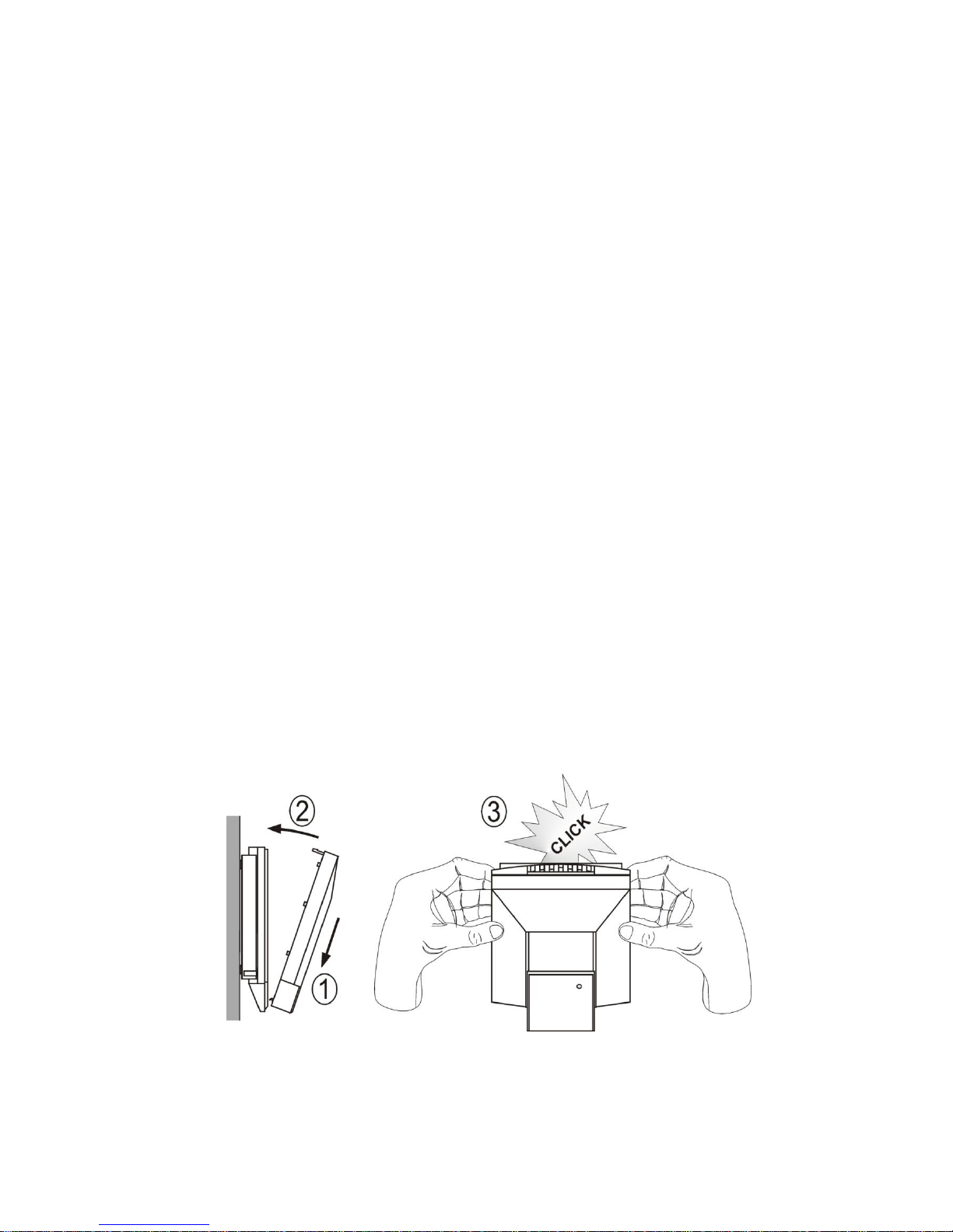
Device demounting
If there is necessary demount the device, insert flat bladed screwdriver max. 3.5 mm wide from
top side into middle device’s air hole. There is fastening member placed, insert screwdriver beyond
the fastening member about 2 cm deep. Then slightly move screwdriver in arrow direction, it unlock
fastening member and the device is partially opened. Remove the screwdriver and take front part of
device at top.Pull front part with pendulum motion and remove front cover. If there is necessary
remove rear part of the device, please disconnect cables and unscrew two holding screws.
Dimensions
Page 5

IE-SNC-T81(2)xx-01 5
Typical application wiring
.
Outputs 4-20 galvanically isolated Outputs 4-20mA galvanically non-isolated
Outputs 0-10V Range of supply voltages and resistor values
Uss . . . . . 9 to 30Vdc
Uss1 . . . . 9 to 30Vdc
Uss2 . . . . 9 to 30Vdc
R1max[Ω] = 50 * Uss1[V] - 450
R2max[Ω] = 50 * Uss2[V] - 450
Rmax[Ω] = 50 * Uss[V] - 450
Rzmin . . 20 kΩ
LCD Info mode
The output range settings can be verified without a use of the computer by
pressing the button on the left side of the device (button is placed behind
small hole - see picture). For button pressing use thin instrument, for example
paper clip.
Upper line of the LCD display shows value of CO2
concentration corresponding to output current 4mA
(output voltage 0V).
Press the button again and upper line of the LCD
display shows value of CO2 concentration
corresponding to output current 20mA (output
voltage 10V).
T8148
T8248
T8148
T8248
Page 6

6 IE-SNC-T81(2)xx-01
Press the button again to get value of temperature
corresponding to output current 4mA (output voltage
0V).
After next pressing of the button LCD shows value
of temperature corresponding to output current
20mA (output voltage 10V).
Press button again to end info mode and display actual measured value.
Notice: during info mode no measurement and no output current (output voltage) generation
proceed. The transmitter stays at info mode 15 s, and then automatically goes back to measuring
cycle.
Procedure of modification of transmitter adjustment:
Device adjustment is performed by means of the optional SP003 communication cable,
connected to USB port of the PC.
It is necessary to have installed configuration program TSensor on the PC. It is free to
download at www.cometsystem.cz/products/reg-TSensor.
During installation please take care about installation of driver for USB communication cable.
Connect SP003 communication cable to the PC. Installed USB driver detect connected cable
and create virtual COM port inside the PC.
Unscrew four screws of the device lid a remove the lid. If device is already installed to
measuring system, disconnect leads from terminals.
Connect SP003 communication cable to the device. Display must light up, or at least must light
up all symbols for one second (if LCD was switched OFF by program before).
Run installed TSensor program and select corresponding communication COM port (as
described above).
When new setting is saved and finished disconnect the cable from the device and place the lid
back to the device.
Error States of the device
Device continuously checks its state during operation. In case error is found LCD displays
corresponding error code:
Error 0 - first line of LCD displays „Err0“. Check sum error of stored setting inside device’s
memory. This error appears if incorrect writing procedure to device’s memory occurred or if
damage of calibration data appeared. At this state device does not measure and calculate
values. It is a serious error, contact distributor of the device to fix.
T8148
T8248
T8148
T8248
Page 7

IE-SNC-T81(2)xx-01 7
Error 2 - there is a reading „Err2“ on LCD display. The CO2 concentration measurement error
or temperature error occurred.
Error 3 - there is a reading „Err3“ on LCD display upper line. Error of internal A/D converter
appeared (converter does not respond, probably damage of A/D converter). At this state
device does not measure temperature and relative humidity. This error does not affect CO2
concentration measurement. It is a serious error, contact distributor of the device.
Error 4 - there is a reading „Err4“ on LCD display. It is internal device error during
initialization of CO2 sensor. Under this condition device does not measure concentration of
CO2. Value read from device is -9999. CO2 sensor is probably damaged. It is a serious error,
contact distributor of the device. This error message is displayed also in case, when the device
is connected to the PC via the optional SP003 communication cable and external power
supply is not used.
Technical parameters
T8148 – temperature and CO2 concentration transmitter
Output: 4 to 20 mA
Power voltage: 9 to 30 V
Power consumption: 1 W during normal operation
max. 4 W for 50 ms with 15 s period
Output in case of error: <3.8 mA or >24 mA
Temperature:
Accuracy: ± 0,5 °C
Range: 0 to +50 ºC
Resolution: 0,1 °C
Response time: t90 < 12 min (air flow approximately 0,3 m/s)
t90 < 25 min (no air flow)
Concentration of CO2:
Accuracy: ± (50 ppm + 2 % of measuring value) at 25°C (77°F) and 1013 hPa
Range: 0 to 2000 ppm
Temp. dependence: typ. 2 ppm CO2 / ºC in the range 0 to 50 ºC (32 to 122°F)
Long term stability: typ. 20 ppm / year
Resolution: 1 ppm
Response time: t90 < 195 s in „SLOW“ measurement mode
t90 < 75 s in „FAST“ measurement mode
T8248 – temperature and CO2 concentration transmitter
Output: 0 to 10 V
Power voltage: 15 to 30 V
Power consumption: 0,5 W during normal operation
max. 3 W for 50 ms with 15 s period
Output in case of error: <-0.1V or >10.5V
Page 8

8 IE-SNC-T81(2)xx-01
Temperature:
Accuracy: ± 0,5 °C
Range: 0 to +50 ºC
Resolution: 0,1 °C
Response time: t90 < 12 min (air flow approximately 0,3 m/s)
t90 < 25 min (no air flow)
Concentration of CO2:
Accuracy: ± (50 ppm + 2 % of measuring value) at 25°C (77°F) and 1013 hPa
Range: 0 to 2000 ppm
Temp. dependence: typ. 2 ppm CO2 / ºC in the range 0 to 50 ºC (32 to 122°F)
Long term stability: typ. 20 ppm / year
Resolution: 1 ppm
Response time: t90 < 195 s in „SLOW“ measurement mode
t90 < 75 s in „FAST“ measurement mode
Operating conditions
Operating temperature range: 0 to +50°C
Operating humidity range: 5 to 95 %RH (no condensation)
Operating pressure range: 850 to 1100 hPa
Recommended interval of calibration: 5 year (CO2), 2 years (temperature)
Protection: IP20
EMC: EN 61326-1, EN 55011
Storage temperature range: -40 to +60 °C
Storage relative humidity range: 5 to 95 % RH (no condensation)
Storage atmospheric pressure: 700 až 1100 hPa
Dimensions: see dimensional drawings
Weight: approximately 150 g
Material of the case with electronics: ABS
End of operation
Device itself (after its life) is necessary to liquidate ecologically!
Technical support and service
Technical support and service is provided by distributor. For contact see warranty certificate.
You can use discussion forum at web address www.forum.cometsystem.cz.
 Loading...