

Page 1

TRANSMITTER T3311, T3411
Programmable relative humidity and temperature transmitter
with serial output RS232 and RS485
With computing of dew point temperature, absolute humidity, specific humidity,
mixing ratio and specific enthalpy
Instruction Manual
Page 2

2 IE-SNC-T33(4)11-04
Transmitter setting from the manufacturer................................................................................................. 3
Transmitter installation .............................................................................................................................. 3
Dimensions............................................................................................................................................. 4
Typical application wiring, connection of terminals.............................................................................. 5
Info mode ............................................................................................................................................... 6
Setting of transmitter, selection of communication protocol .....................................................................6
Description of communication protocols ................................................................................................... 8
Modbus RTU.......................................................................................................................................... 8
Supported functions ........................................................................................................................... 8
Jumper and button.............................................................................................................................. 8
Description of supported function ..................................................................................................... 9
03 (0x03): Reading of 16-bit registers (Read Holding Registers)........................................................ 9
04 (0x04): Reading 16-bit input gates (Read Input Registers)............................................................. 9
16 (0x10): Setting of several 16-bit registers (Write Multiple Registers) ............................................ 9
Exception Responses.......................................................................................................................... 12
Exception codes.................................................................................................................................. 12
Modbus CRC ................................................................................................................................... 12
Procedure during calculation of Modbus CRC................................................................................... 13
Modbus registers of the transmitter ................................................................................................. 13
Example of communication ............................................................................................................. 13
Reading of temperature, address 0x0031 ........................................................................................... 13
Reading of relative humidity, address 0x0032 ................................................................................... 14
Reading of computed value, address 0x0033 ..................................................................................... 14
Reading of all values at once, address block 0x0031 to 0x0033........................................................ 14
Protocol compatible with Advantech-ADAM standard....................................................................... 15
Jumper.............................................................................................................................................. 15
General syntax of commands........................................................................................................... 15
Description of supported functions.................................................................................................. 16
Configuration of transmitter............................................................................................................... 16
Response of the transmitter ................................................................................................................ 16
Check sum (CRC) .............................................................................................................................. 16
Reading of the temperature ................................................................................................................ 16
Reading of humidity........................................................................................................................... 16
Reading of computed value................................................................................................................ 17
Query to adjusted configuration ......................................................................................................... 17
Reading of device name ..................................................................................................................... 17
Reading of firmware version.............................................................................................................. 17
Format of data.................................................................................................................................. 18
Error states.......................................................................................................................................... 18
Communication protocol ARION - AMiT company........................................................................... 18
Supported frames ............................................................................................................................. 18
Supported function description ........................................................................................................ 19
Error States of the transmitter .................................................................................................................. 19
Error 0 .................................................................................................................................................. 19
Error 1 .................................................................................................................................................. 19
Error 2 .................................................................................................................................................. 20
Error 3 .................................................................................................................................................. 20
Readings on LCD display ........................................................................................................................ 20
Technical parameters of the instrument: .................................................................................................. 21
Measuring parameters:......................................................................................................................... 21
End of operation....................................................................................................................................... 22
Technical support and service .................................................................................................................. 22
Appendix A .............................................................................................................................................. 23
Connection of ELO E06D converter (RS232/RS485) ......................................................................... 23
Page 3

IE-SNC-T33(4)11-04 3
Instruction Manual for use of temperature and relative humidity transmitter:
T3311 (RS232)
T3411 (RS485)
Transmitter is designed for measurement of ambient temperature and relative humidity of air
without aggressive ingredients with computing one of the following values: dew point temperature,
absolute humidity, specific humidity, mixing ratio and specific enthalpy. Please read instruction
manual before the first transmitter connection. Transmitter T3311 communicates via link RS232,
transmitter T3411 via link RS485. Supported communication protocols are Modbus RTU, protocol
compatible with standard Advantech-ADAM and ARION. Temperature and relative humidity
sensors are non-removable instrument parts. Measured and computed values are displayed on dual
line LCD display. The first line displays temperature. Value displayed on the second line is
selectable among relative humidity and computed value. It is also possible to display both readings
with cyclic overwriting in 4 seconds interval. Display can be also switched OFF totally. Output link
RS485 of transmitter T3411 is galvanic isolated. Output link RS232 of transmitter T3311 is NOT
galvanic isolated. Setting of all transmitter parameters is enabled in accordance with procedure
described in chapter „Setting of transmitter, selection of communication protocol“ or by means of
commands of selected communication protocol. For detailed description of features of protocols see
chapter „Description of communication protocols“.
Transmitter setting from the manufacturer
If special setting was not required in the order transmitter is set from the manufacturer to the
following parameters:
communication protocol: Modbus RTU
transmitter address: 01H
communication speed: 9600Bd, without parity, 2 stop bits
display: switched ON
value displayed at lower line: relative humidity only
preset computed value: dew point temperature
Transmitter installation
Transmitter is designed for wall mounting. There are two mounting holes at the sides of the
case. It is NOT recommended to use the device for long time under condensation conditions. It
could be the cause of water steam condensation inside the sensor’s cover into water phase. This
liquid phase stays inside sensor’s cover and can’t escape from the cover easily. It can dramatically
increase response time to relative humidity change. If water condensation occurs for longer time it
can cause sensor damage. Similar effect can occur under water aerosol conditions. Don’t connect
transmitter while power supply voltage is on. Interconnection terminals are accessible after
unscrewing four screws and removing the lid. Lace the cable through a gland at the case wall.
Connect the cable to terminals with respecting the signal polarity (see figure). Terminals are selfclamping and can be opened by a suitable screwdriver. For the opening, insert the screwdriver to
smaller terminal hole and lever by him. Do not forget to tighten glands and case lid with inserted
packing after cables connecting. It is necessary for warranting of protection IP65. Working position
is with the bronze filter downwards – see figure.
Transmitter T3311 is supplied with connection cable equipped with connector for connection to
RS232 interface. For T3411 transmitter (RS485) it is recommended to use shielded twisted copper
cable (e.g. SYKFY). Outside diameter of the cable must be from 3 to 6.5 mm, maximal length
1200m. The cable must be located at indoor rooms.
Page 4
4 IE-SNC-T33(4)11-04
Nominal cable impedance should be 100 Ω, loop resistance max. 240 Ω, cable capacity max.
65 pF/m. Suitable cable is e.g. SYKFY 2x2x0,5 mm2, where one wire pair serves for transmitter
powering and the other pair for communication link.
The cable should be led in one line, i.e. NOT to „tree“ or „star“. Termination resistor should
be located at the end. For short distance other topology is allowed. Terminate the network by a
termination resistor. The value of the resistor is recommended about 120 Ω. For short distance
termination resistor can be left out.
The cable should not be led in parallel along power cabling. Safety distance is up to 0.5 m,
otherwise undesirable induction of interference signals can appear.
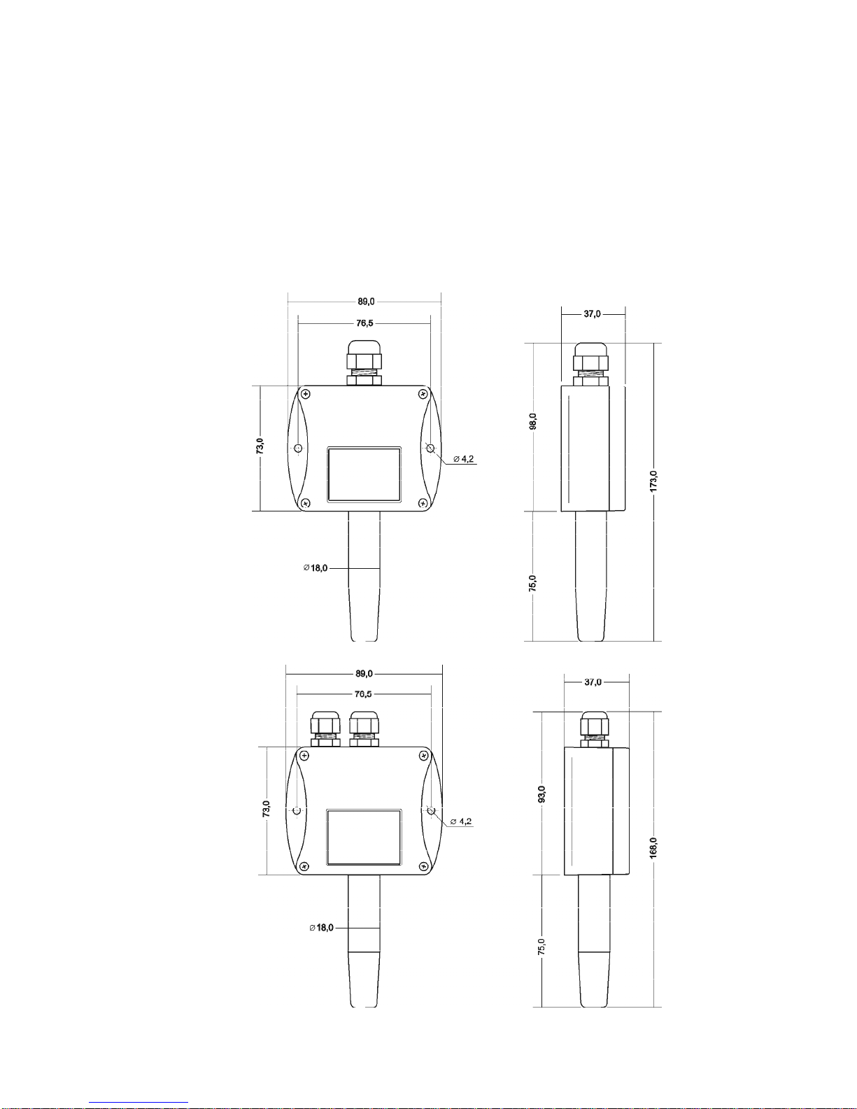
Dimensions
T3311 – RS232
T3411 – RS485
Page 5
IE-SNC-T33(4)11-04 5
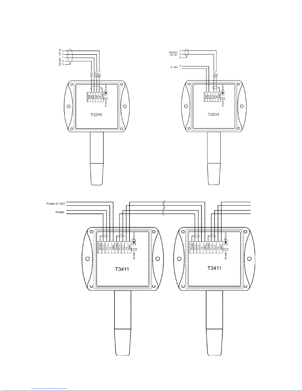
Typical application wiring, connection of terminals
T3311 – power from communication port T3311 – power from external voltage source
T3411 – RS485
Page 6

6 IE-SNC-T33(4)11-04
Info mode
If in doubt of setting of installed transmitter, verification of its address is enabled even
without using computer. Power should be connected.
Unscrew transmitter cover and shortly press button next to connection terminals (jumper
should be opened). Actual adjusted address of transmitter is displayed on LCD display at decimal
base. Next press of button exits info mode and actual measured values are displayed.
Note: No measurement and communication is possible during info mode. If transmitter stays in info
mode for longer than 15 s, transmitter automatically returns to measuring cycle.
Setting of transmitter, selection of
communication protocol
Each new setting of transmitter parameters is stored in its internal memory1. If modification of
transmitter setting is needed (communication protocol, its parameters, setting of LCD display), it is
recommended to use of User’s software available at www.cometsystem.cz (providing all settings of
transmitter parameters) or proceed in following way (support basic setting):
• Connect transmitter with PC, for T3411 (RS485) use converter RS485/RS232.
• Run program „HyperTerminal“ on your computer – it is a part of Windows operating system
(Start → Program Files → Accessory → Communication → HyperTerminal) and set
transmission parameters. I.e. enter name of new connection (e.g. Transmitter), press button OK,
window „Connect“ appears. In field „Connect by means of“ select COM port, which transmitter
is connected to (e.g. COM1) and press OK. In following window „COM1 – Features“ enter to
field:
„Bits per second“ 9600
“Data bits“ 8
“Parity“ None
“Number of stop-bits“ 1
“Flow control“ None
Continue by pressing OK.
1
During writing to transmitter memory no power failure should appear! Such failure can cause
damage of other settings stored in the transmitter!
Page 7
IE-SNC-T33(4)11-04 7
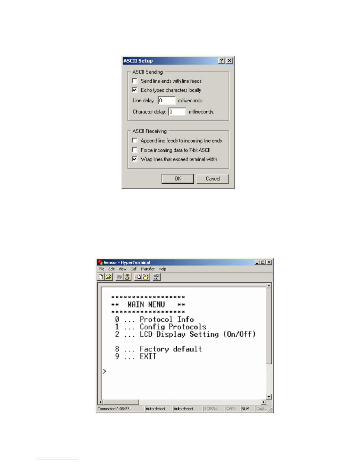
• Select item „File“, „Features“ in menu. Select bookmark „Setup“, in the window, click on
„ASCII Setup... “ and modify all items in accordance with following figure and press OK
• Unscrew 4 screws of transmitter cover and remove it. Plug in jumper.
• Keep the button inside the transmitter pressed, only now you can connect power voltage and
then release the button. If transmitter is powered directly from PC communication port (for
interface RS232), it is necessary first to disconnect communication cable, then to keep the
button pressed, to connect communication cable (and also power) and only now release the
button.
• LCD display of the transmitter displays „PC“.
• Running HyperTerminal displays main menu.
Page 8

8 IE-SNC-T33(4)11-04
Select required items to set the transmitter:
0 … Displays actual setting of the transmitter
1 … Selection of communication protocol and setting of its parameters (transmitter address,
communication speed…). For entering numeric values use digits 0 to 9 and characters
„A“ to „F“ (upper case letters), transmitter address is entered always as two digits
hexadecimal number (no decimal, e.g. address 11 i.e. Bh must be entered as 0B).
2 … Setting of LCD display of the transmitter (display switched ON/ switched OFF,
selection of displayed values)
8 … Setting communication to default value from manufacturer (Modbus, address 01h, 9600
Bd)
9 … End of setting
All changes in setting are continuously stored automatically.
• If needed close transmitter again with cover.
Description of communication protocols
To change communication protocol use User’s software or proceed in accordance with chapter
„Setting of transmitter, selection of communication protocol“
Note: After switching ON the power of the transmitter it can last up to 2 s before the transmitter
starts to communicate and measure!
Modbus RTU
Control units communicate on master-slave principle in half-duplex operation. Only master
can send request and only addressed device responds. During sending of request no other slave
station should respond. During communication, data transfer proceeds in binary format. Each Byte
is sent as eight bit data word in format: 1 start bit, data word 8 bit (LSB first), 2 stop bits2, without
parity. Transmitter supports communication speed from 110Bd to 115200Bd.
Sent request and response have syntax: ADDRESS OF DEVICE – FUNCTION – Modbus CRC
Supported functions
03 (0x03): Reading of 16-bit registers (Read Holding Registers)
04 (0x04): Reading of 16-bit input gates (Read Input Registers)
16 (0x10): Setting of more 16-bit registers (Write Multiple Registers)*
3
Jumper and button
Jumper and button are located next to connection terminals. If communication protocol Modbus is
selected the function of jumper and button is as follows:
• Jumper opened – transmitter memory is protected from writing, from transmitter side it is
only enabled to read measured value, writing to memory is disabled (no change of
transmitter address, communication speed and LCD setting is enabled)
• Jumper closed – writing to transmitter memory is enabled by means of User’s software or
function 16 (0x10): Setting of several 16-bit registers (Write Multiple Registers)
• Jumper closed and button pressed for longer than three seconds – causes restoring of
manufacturer setting of communication protocol, i.e. sets transmitter address to 01h and
communication speed to 9600Bd
2
Transmitter sends two stop bits, for receive one stop bit is enough.
3
See detailed description of this function.
Page 9

IE-SNC-T33(4)11-04 9
• Jumper opened and button shortly pressed – transmitter goes to Info mode, see chapter „Info
mode“
Description of supported function
03 (0x03): Reading of 16-bit registers (Read Holding Registers)
Function serves for reading of values from transmitter. Addresses of available registers are listed
in chapter „Modbus registers of the transmitter on page 13.“
Request:
---------------------------------------------------------------------------------------------FUNCTION Function code 0x03
---------------------------------------------------------------------------------------------DATA Initial address Hi 0x??
Initial address Lo 0x??
--------------------------------------------------------------------------- Number of registers Hi 0x??
Number of registers Lo 0x??
---------------------------------------------------------------------------------------------Response:
---------------------------------------------------------------------------------------------FUNCTION Function code 0x03
---------------------------------------------------------------------------------------------DATA Number of Bytes 0x??
--------------------------------------------------------------------------- States of register Hi 0x??
States of register Lo 0x??
...
States of register Hi 0x??
States of register Lo 0x??
----------------------------------------------------------------------------------------------
Exceptional response:
---------------------------------------------------------------------------------------------FUNCTION Function code 0x83
---------------------------------------------------------------------------------------------DATA Exception code 0x??
---------------------------------------------------------------------------------------------During sending of query to transmitter initial register address and number of registers to read are
sent. Register addresses are indexed from zero – register 0x2001 se physically sent as value 0x2000,
0x2002 as 0x2001…)
04 (0x04): Reading 16-bit input gates (Read Input Registers)
This function is also possible to use for reading values from transmitter, syntax is the same as with
function 03 (0x03): Reading of 16-bit registers. Addresses of available registers are specified
in chapter „Modbus registers of the transmitter on page 13.“
16 (0x10): Setting of several 16-bit registers (Write Multiple Registers)
Setting of transmitter address and communication speed is possible to perform by writing to
transmitter registers.
Attention! During writing to transmitter registers it is not enabled to write any number of registers.
Always below procedure should be strictly followed. If procedure is not followed undoable loss of
Page 10

10 IE-SNC-T33(4)11-04
important settings stored in transmitter can occur! It is strongly recommended to use User’s
software to set all transmitter’s parameters or use procedure described in chapter „Setting of
transmitter, selection of communication protocol“ for transmitter setting instead.
Request:
----------------------------------------------------------------------------------------------------FUNCTION Function code 0x10
----------------------------------------------------------------------------------------------------DATA Initial address Hi 0x??
Initial address Lo 0x??
---------------------------------------------------------------------------- Number of registers Hi 0x??
Number of registers Lo 0x??
---------------------------------------------------------------------------- Number of Bytes 0x??
(of sent data)
----------------------------------------------------------------------------------------------------Response:
----------------------------------------------------------------------------------------------------FUNCTION Function code 0x10
----------------------------------------------------------------------------------------------------DATA Initial address Hi 0x??
Initial address Lo 0x??
---------------------------------------------------------------------------- Number of registers Hi 0x??
Number of registers Lo 0x??
----------------------------------------------------------------------------------------------------Exceptional response:
----------------------------------------------------------------------------------------------------FUNCTION Function code 0x90
----------------------------------------------------------------------------------------------------DATA Exception code 0x??
-----------------------------------------------------------------------------------------------------
Procedure during writing to transmitter registers:
• transmitter address is stored at Modbus address 0x2001 as binary number
• code of communication speed is stored at Modbus address 0x2002
Communication
speed [Bd]
Code of
communication
speed [hex]
110 94F2
300 369D
600 1B4F
1200 0DA7
2400 06D4
4800 036A
9600 01B5
14400 0123
19200 00DA
38400 006D
56000 004B
57600 0049
115200 0024
Page 11

IE-SNC-T33(4)11-04 11
1. Close jumper located next to connection terminals of the transmitter.
2. Read entire area 0x2001 to 0x2040 to master device. At address 0x2040 check sum of entire
area is stored. It is calculated as sum of 16bit values from addresses 0x2001 to 0x2039.
Stored are lowest 16 bits of this sum - enables to check correct reading of the area.
3. Modify content corresponding to addresses 0x2001 and 0x2002 in master device as
required. Setting of other values should not be changed!
4. Calculate new check sum of entire area, i.e. sum of 16bit values corresponding to values at
addresses 0x2001 to 0x2039 and store lowest 16 bits to position corresponding to address
0x2040.
5. Write such modified area together from master device to addresses 0x2001 to 0x2040.
6. Open jumper.
Example: Transmitter with address 01h, communication speed 9600Bd, to change to address 9Fh
and 115200Bd
For data area reading the following is sent via link: 01 03 20 00 00 40 4F FA
01 transmitter address
03 command for reading of 16-bit registers
20 00 initial address (sent address is indexed from zero, during Modbus request for
reading of address 0x2001 physically is sent 0x2000 via link)
00 40 read 64 registers (0x40), i.e. 128 Byte
4F FA CRC of Modbus
response of the transmitter is:
01 03 80 00 01 01 B5 00 00 30 30 3B 4B 77 D3 BD 35 00 00 00 00 00 00 00 00 00 00 00 00 00 00
00 00 00 00 00 00 00 00 00 00 00 00 00 00 00 00 00 00 00 00 84 70 00 00 86 2A 00 00 84 44 AA
80 85 07 A8 D0 57 7E 5F 94 F3 DC 00 12 2E DD 78 0C 40 AA 77 D3 F2 C4 00 12 17 78 77 F5 F3
EC 00 12 ED BF 77 D5 4F 10 77 D8 FF FF FF FF 40 DE 77 D3 2E F7 78 0C 06 5C 00 01 00 00 00
00 F3 DC 00 12 42 9F 53 2D 2C 8C
01 transmitter address
03 code of command (reading 16-bit registers)
80 number of Bytes of response (0x80, i.e. 128 Byte)
00 01 address content 0x2001, i.e. original address of transmitter 01h
01 B5 address content 0x2002, i.e. code of corresponding communication speed 9600Bd
…
…
53 2D check sum of entire area 0x2001 to 0x2039
(0001+01B5+0000+3030+…+0012+429F = 0x532D)
2C 8C CRC of Modbus
Modification of data from read area:
00 9F 00 24 00 00 30 30 3B 4B 77 D3 BD 35 00 00 00 00 00 00 00 00 00 00 00 00 00 00 00 00 00
00 00 00 00 00 00 00 00 00 00 00 00 00 00 00 00 00 84 70 00 00 86 2A 00 00 84 44 AA 80 85 07
A8 D0 57 7E 5F 94 F3 DC 00 12 2E DD 78 0C 40 AA 77 D3 F2 C4 00 12 17 78 77 F5 F3 EC 00
12 ED BF 77 D5 4F 10 77 D8 FF FF FF FF 40 DE 77 D3 2E F7 78 0C 06 5C 00 01 00 00 00 00 F3
DC 00 12 42 9F 52 3A
00 9F new address of the transmitter (original address was 00 01)
00 24 new code of corresponding communication speed 115200Bd (original was 01B5)
…
…
52 3A new check sum of entire area (009F+0024+0000+…+0012+429F = 0x523A)
Write such modified area together from master device to the transmitter, area 0x2001 to 0x2040
Page 12

12 IE-SNC-T33(4)11-04
01 10 20 00 00 40 80 00 9F 00 24 00 00 30 30 3B 4B 77 D3 BD 35 00 00 00 00 00 00 00 00 00 00
00 00 00 00 00 00 00 00 00 00 00 00 00 00 00 00 00 00 00 00 00 00 00 00 84 70 00 00 86 2A 00 00
84 44 AA 80 85 07 A8 D0 57 7E 5F 94 F3 DC 00 12 2E DD 78 0C 40 AA 77 D3 F2 C4 00 12 17
78 77 F5 F3 EC 00 12 ED BF 77 D5 4F 10 77 D8 FF FF FF FF 40 DE 77 D3 2E F7 78 0C 06 5C
00 01 00 00 00 00 F3 DC 00 12 42 9F 52 3A 61 22
01 original transmitter address is still valid, i.e. 01h
10 code of command, setting more 16-bit registers
20 00 initial address
00 40 number of write registers
80 number of Bytes of sent data
61 22 CRC of Modbus
After successful writing to the transmitter, transmitter responds: 01 10 20 00 00 40 CA 39 (still with
old address at original communication speed) and after response it sets to new values. In case of
different number of data or incorrect check sum of the entire area writing to transmitter is not
performed.
Exception Responses
After sending query to the transmitter, master device waits for normal response. After master device
query one of the following events can occur:
1. If transmitter receives a query without communication error and query is possible to process,
master device receives response.
2. If transmitter does not receive all queries due to communication error, no response is sent. Main
program is able to process condition of exceeding of time for query.
3. If transmitter receives a query, but detects communication error (CRC), no response is sent.
Main program is able to process condition of exceeding of time for query.
4. If transmitter receives a query without communication error, but cannot process it, master
device receives exception response, which informs master device on error nature.
Exception Response
- has two fields to distinguish it from normal response:
1. Function code field
2. Data field.
ad1 Function code field
In normal response of slave device function code of original query corresponds to function code of
response. All function codes have most significant bit (MSB) equal to 0. In exception response
slave device sets most significant bit of function code to 1. Main station recognizes exception
response by means of this bit and can check data field for exception code.
ad2 Data field
In exception response transmitter returns exception code in data field. Event causing exception is
determined this way.
Exception codes
0x01 Invalid function. Function code in query is not allowed action for transmitter.
0x02 Invalid data address. Data address received in query is not allowed address for transmitter.
Modbus CRC
Check sums of entire Modbus messages are mostly automatically inserted to the end of request by
communication programs themselves. In case there is a need to insert to generate Modbus CRC to
program itself, the way of calculation is as follows:
Page 13

IE-SNC-T33(4)11-04 13
Procedure during calculation of Modbus CRC
1. To fill 16-bit register with value 0xFFFF (all bits set to 1). Let us call this register „CRC
register“.
2. Perform logic function Exclusive OR with first eight bit message Byte with lower eight bits
of CRC register. Store result to CRC register.
3. Shift content of CRC register of one bit to the right (towards to LSB), enter 0 as upper bit of
CRC. Memorize values of lowest shifted bit (LSB).
4. If LSB was 0, then repeat step 3 (other shift).
If LSB was 1, then perform Exclusive OR CRC register with value 0xA001.
5. Repeat steps 3 and 4 as long as eight shifts proceed. After eight shifts eight bit Byte is
processed.
6. Repeat steps 2 to 5 to the next of eight bit Byte of message as long as all Bytes are
proceeded.
7. In the end after processing of all message Bytes check sum value is stored in CRC register.
8. During connection of check sum to the message lower Byte of CRC register is sent as first,
then upper Byte of CRC register.
Modbus registers of the transmitter
Variable Unit Address Format Size Status
Measured temperature [°C] 0x0031 Int*10 BIN16 R
Measured relative humidity [%] 0x0032 Int*10 BIN16 R
Computed value * [°C] 0x0033 Int*10 BIN16 R
Address of transmitter [-] 0x2001 Int BIN16 R/W*
Code of communication speed [-] 0x2002 Int BIN16 R/W*
Serial number of transmitter Hi [-] 0x1035 BCD BIN16 R
Serial number of transmitter Lo [-] 0x1036 BCD BIN16 R
Version of Firmware Hi [-] 0x3001 BCD BIN16 R
Version of Firmware Lo [-] 0x3002 BCD BIN16 R
Explanation:
• * to choice of computed value type use User’s software
• Int*10 register is in format integer*10
• R register is designed only for reading
• W* register is designed for writing, for details see description function 16 (0x10): Setting
of several 16-bit registers (Write Multiple Registers)
Note: In case there is a need for reading of measured values from transmitter with higher resolution
than one decimal, measured values in transmitter are stored also in „Float“ format, which is not
directly compatible with IEEE754.
Example of communication
In all examples communication with transmitter at address 01h is supposed
Reading of temperature, address 0x0031
Modbus command:
address transmitter: 01
reading 16-bit registers 03
initial address Hi 00
initial address Lo 31
number read registers Hi 00
number read registers Lo 01
Via link is physically sent: 01 03 00 30 00 01 84 05
Page 14

14 IE-SNC-T33(4)11-04
Received response from transmitter: 01 03 02 00 F4 B9 C3
address transmitter: 01
reading 16-bit registers 03
Number Byte 02
State of register Hi 00
State of register Lo F4 (0x00F4 = 244 = 24.4 °C)
Modbus CRC Lo B9
Modbus CRC Hi C3
Reading of relative humidity, address 0x0032
Modbus command:
address transmitter: 01
reading 16-bit registers 03
initial address Hi 00
initial address Lo 32
number read registers Hi 00
number read registers Lo 01
Via link is physically sent: 01 03 00 31 00 01 D5 C5
Received response from transmitter: 01 03 02 01 6C B9 F9
address transmitter: 01
reading 16-bit registers 03
Number Byte 02
State of register Hi 01
State of register Lo 6C (0x016C = 364 = 36.4 %RH)
Modbus CRC Lo B9
Modbus CRC Hi F9
Reading of computed value, address 0x0033
Modbus command:
address transmitter: 01
reading 16-bit registers 03
initial address Hi 00
initial address Lo 33
number read registers Hi 00
number read registers Lo 01
Via link is physically sent: 01 03 00 32 00 01 25 C5
Received response from transmitter: 01 03 02 FF 3E 78 64
address transmitter: 01
reading 16-bit registers 03
Number Byte 02
State of register Hi FF
State of register Lo 3E (0xFF3E = -194 = -19.4)
Modbus CRC Lo 78
Modbus CRC Hi 64
Reading of all values at once, address block 0x0031 to 0x0033
Modbus command:
address transmitter: 01
reading 16-bit registers 03
initial address Hi 00
Page 15

IE-SNC-T33(4)11-04 15
initial address Lo 31
number read registers Hi 00
number read registers Lo 03
Via link is physically sent: 01 03 00 30 00 03 05 C4
Received response from transmitter: 01 03 06 FF C4 01 14 FF 38 C5 71
transmitter address: 01
reading 16-bit registers 03
Number Byte 06
State of register Hi FF
State of register Lo C4 (0xFFC4 = -60 = -6.0 °C)
State of register Hi 01
State of register Lo 14 (0x0114 = 276 = 27.6 %RH)
State of register Hi FF
State of register Lo 38 (0xFF38 = -200 = -20.0 °C)*
Modbus CRC Lo C5
Modbus CRC Hi 71
* Computed value is preset by factory to Dew Point Temperature, to choice use User’s software
Protocol compatible with Advantech-ADAM standard
Control units communicate on master-slave principle in half-duplex operation. Only master
can send requests and only addressed device responds. During sending request any of slave devices
should respond. During communication data is transferred in ASCII format (in characters). Each
Byte is sent as two ASCII characters (value 0x2F is sent as pair of characters 0x32, 0x46, i.e.
characters „2“ and „F“). All commands and values MUST be entered in CAPITAL LETTERS !
Transmitter supports communication speed from 1200Bd to 115200Bd, parameters of
communication link are 1 start bit + eight bit data word (LSB first) + 1 stop bit, without parity.
Jumper
Jumper is located next to connection terminals. If communication protocol compatible with
standard Advantech-ADAM is selected, its function is the following:
• If jumper during switching ON the power is closed, transmitter always communicates with
following parameters regardless stored setting in the transmitter:
communication speed 9600 Bd, without check sum, transmitter address 00h
• If jumper during switching ON the power is not closed, transmitter communicates in
accordance with stored setting.
• If jumper is closed during transmitter operation, transmitter temporarily changes its address
to 00h, it will communicate in the same communication speed as before closing jumper and
will communicate without check sum. After jumper is opened setting of address and check
sum is reset in accordance with values stored in transmitter.
• Communication speed and check sum are possible to change only if jumper is closed (see
chapter Configuration of transmitter).
General syntax of commands
[distinguishing character][device address][command][data][check sum][CR]
Valid distinguishing characters towards to device are: $, #, %
Device address contents 2 ascii bytes in hexadecimal code (upper case letters) representing one
byte of binary address (e.g. „3“ „F“ corresponds to address 3Fh, i.e. 63, is sent as 0x33, 0x46)
Check sum: enabled to switch ON/switch OFF
CR ... 1 byte (0Dh)
Page 16

16 IE-SNC-T33(4)11-04
Description of supported functions
Configuration of transmitter
Syntax of command: %AANNTTCCFF cr
Meaning of symbols:
AA … current address of transmitter 00…FF (hexadecimal)
NN … new address of transmitter 00…FF (hexadecimal)
TT … code of transmitter (2Ch…combined transmitter of temperature and humidity)
CC ... code of communication speed
Code speed [Bd]
03 1200
04 2400
05 4800
06 9600
07 19200
08 38400
09 57600
0A 115200
• Communication speed and check sum are possible to change only if jumper is closed
o Change in communication speed activates only after transmitter power is switched
OFF and switched ON again.
o Change in setting of check sum activates immediately after jumper is opened
• If address is changing
o and jumper is closed, transmitter responds with address 00h again, and newly set
address will be activated after jumper is opened.
o and jumper is not closed, change is activated immediately.
• If attempt occurs to write incorrect data to the transmitter (and syntax is correct), transmitter
responds with error message.
Response of the transmitter
1. If syntax of command is not correct, transmitter does not respond at all (e.g. no check sum is
received though it is switched ON, check sum is not correct, string is not complete or
contents invalid character).
2. If syntax is correct, but required operation is not correct, transmitter returns error message in
format
? AA cr
this state appears if we try to change communication speed and check sum and jumper is not
closed.
3. If command is executed, transmitter responds:
! AA cr
Check sum (CRC): it is the sum of all characters before it, its lowest byte is applied.
Reading of the temperature
Syntax command: #AA0 cr
Response: > (temperature) cr (e.g. >-012.30 cr)
Reading of humidity
Syntax command: #AA1 cr
Response: > (humidity) cr (e.g. >+044.30 cr)
FF … data format and check sum:
D7 D6 D5 D4 D3 D2 D1 D0
xxxx xx00 format "Engineering units"
x0xx xx00 check sum switched OFF
x1xx xx00 check sum switched ON
Page 17

IE-SNC-T33(4)11-04 17
Reading of computed value
Syntax command: #AA2 cr
Response: > (computed value) cr (e.g. >+004.30 cr)
Query to adjusted configuration
Syntax command: $AA2 cr
Response: !AATTCCFF cr symbols correspond with paragraph
"Configuration of transmitter"
Reading of device name
Syntax command: $AAM cr
Response: !AAT3311 cr or !AAT3411 cr (accordingly with transmitter
model)
Reading of firmware version
Syntax command: $AAF cr
Response: !AA(version) cr reads version number of transmitter firmware
Example 1: Change of transmitter address during operation (without closed jumper, CRC
switched OFF)
Transmitter, which had address 23h is configured to address 24h, speed 9600 Bd,
without CRC, setting of communication speed and CRC must not change (setting of
communication speed and CRC is not possible to change without closed jumper).
Command: %23242C0600 cr
Response: !24 cr
Example 2: Reading of temperature from transmitter without closed jumper, transmitter address
01h, without check sum.
Command: #010 cr
Response: > +020.50 cr
with check sum:
Command: #010 B4 cr
where it is sent: 23 30 31 30 42 34
0D
calculation of CRC: 23h+30h+31h+30h = B4h, then CRC = B4h, it is sent as
0x42, 0x34
Response: >+020.50 8E cr
where it is sent: 3E 2B 30 32 30 2E 35 30 38 45
0D
calculation of CRC: 3Eh+2Bh+30h+32h+30h+2Eh+35h+30h=18Eh then CRC =
8Eh, then it is sent as 0x38, 0x45
Example 3: Setting of transmitter to address 9F, communication speed remains 9600 Bd, check
sums are switched ON (jumper should be closed because setting of CRC will be
changed):
- with jumper, transmitter always reports from address „00“ without CRC
Command: %009F2C0640 cr
Response: !00
After jumper is opened transmitter address changes to 9Fh
Page 18

18 IE-SNC-T33(4)11-04
Format of data
Transmitter uses data format „Engineering units“, i.e. fixed decimal point. Temperature,
humidity and computed value are displayed with 2 digits behind decimal point, second digit behind
decimal point is always zero
General writing: „>±xxx.x0 cr“
Examples: >-050.20 cr >+000.00 cr >+025.80 cr
Error states
>-0000 cr lower limit of temperature, error in measurement of humidity and computed
value
>+9999 cr upper limit of temperature, error in measurement of humidity and computed
value
Communication protocol ARION - AMiT company
The device supports communication protocol ARION version 1.00, simplex and half duplex
modes and communication speeds 9600, 19200, 38400 and 57600 Baud.
Supported frames
0x20 ACK Positive response
0x21 NAK Negative response
0x22 STRQ (Resp.req. must be 1) Status request
0x23 STT Slave status, mode, guard time
0x24 MODE Set Mode
0x26 VRRQ (Resp.req. must be 1) Request for firmware and protocol version
0x27 VER Response of firmware and protocol version
0x28 IDRQ (Resp.req. must be 1) Module identification request
0x29 MID Module identification
0x2A FTRQ (Resp.req. must be 1) Request for list of supported frames
0x2B FTL List of supported frames
0x2C CLRQ (Resp.req. must be 1) Request for class of module
0x2D CLS Class of module
0x30 DTRQ (Resp.req. must be 1) Data request
0x56 data 24 analog values by14 bit
0x58 data 8 analog values by 21 bit
0x80+Address+Response Request Start of frame
0x80 Stop End of frame
Page 19

IE-SNC-T33(4)11-04 19
Supported function description
0x24 MODE – Set mode
Device supports next modes: 0x00, 0x01 Simplex
0x02, 0x03 Half Duplex over RS232, RS485 line
Lost of connection detection (Guard time) is always set to zero, it means lost of connection is not
detected, guard time value sent by command is not important, it is not checked.
0x56 – 24 analog values by 14 bit:
The values are sent in data sequence: temperature, relative humidity, computed value4, the rest
values are always zero. Range of all values is restricted from -819.2 to +819.1. Right values are into
range from -819.1 to +819.0, limit values are reserved for over range or error states indication,
where -819.2 = Error2, 819.1 = Error1 (see chapter Error States of the transmitter). Application
setup follow: Range 8192
ElMin -8192
ElMax 8191
PhysMin -819.2
PhysMax 819.1
0x58 – 8 analog values by 21 bit:
Similarly as 0x56, range of values is from -999.9 to +999.9, where limit values are reserved for over
range or error states indication.
For detailed protocol description see ARION protocol description at www.amit.cz
If necessary, change of device setup (address, communication speed) is possible by steps described
in chapter Setting of transmitter, selection of communication protocol.
Actual adjusted address of device is available by press of button next to connection terminals
(jumper should be opened). Then device displays its address on LCD display at decimal base. Next
press of button exits this mode and actual measured values are displayed. While address shown,
device don’t communicate.
Error States of the transmitter
Transmitter continuously checks its state during operation. In case error is found LCD displays
corresponding error code:
Error 0
First line displays „Err0“.
Error of check sum CRC of stored setting in transmitter memory. This error appears if writing
procedure to transmitter memory is not correct, if writing to other address than allowed, optionally
if damage of calibration data appeared. At this state transmitter does not measure and calculate
values. It is the serious error, contact distributor of the instrument to fix.
Error 1
Measured (calculated) value is over upper limit of allowed full scale range. There is a reading
„Err1“ on LCD display. Value read from the transmitter is +999,9.
This state appears in case of:
• Measured temperature is higher than approximately 600°C (i.e. high non-measurable
resistance of temperature sensor, probably opened circuit).
4
Selection of computed value type is provided by User’s Software
Page 20

20 IE-SNC-T33(4)11-04
• Relative humidity is higher than 100%, i.e. damaged humidity sensor, or humidity
calculation of humidity is not possible (due to error during temperature measurement)
• Computed value – calculation of the value is not possible (error during measurement of
temperature or relative humidity or value is over range)
Check connection of measuring sensors.
Error 2
There is a reading „Err2“ on LCD display. Measured (calculated) value is below lower limit of
allowed full scale range. Value read from the transmitter is -999,9.
This state appears in case of:
• Measured temperature is lower than approximately -210°C (i.e. low resistance of
temperature sensor, probably short circuit).
• Relative humidity is lower than 0%, i.e. damaged sensor for measurement of relative
humidity, or calculation of humidity is not possible (due to error during temperature
measurement)
• Computed value – calculation of computed value is not possible (error during measurement
of temperature or relative humidity)
Check connection of measuring sensors.
Error 3
There is a reading „Err3“ on LCD display upper line.
Error of internal A/D converter appeared (converter doe not respond, probably damage of A/D
converter). No measurement and calculations of values are proceeded. It is a serious error, contact
distributor of the instrument.
Readings on LCD display
°C
Reading next to this symbol is measured temperature or error state of value.
%RH
Reading next to this symbol is measured relative humidity or error state of value.
°C DP
Reading next to this symbol is calculated dew point temperature or error state of value.
first left arrow
Is on if jumper is closed.
second left arrow
Is on if button is pressed.
On LCD display is shown the value with corresponding unit for temperature, relative humidity and
dew point temperature. For rest values is shown only number (without corresponding unit).
Page 21

IE-SNC-T33(4)11-04 21
Technical parameters of the instrument:
Measuring parameters:
Ambient temperature (RTD sensor Pt1000/3850ppm):
Measuring range: -30 to +80 °C
Resolution of display: 0.1 °C
Accuracy: ± 0.4 °C
Relative humidity (reading is temperature compensated at entire temperature range):
Measuring range: 0 to 100 %RH (see Transmitter installation)
Resolution display: 0.1 %RH
Accuracy: ± 2.5 %RH from 5 to 95 %RH at 23 °C
The value computed from ambient temperature and relative humidity:
Display resolution: 0,1 °C
You can choice one of the next value:
Dew point temperature
Accuracy: ±1,5 °C at ambient temperature T < 25°C and RH >30%
Range: -60 to +80 °C
Absolute humidity
Accuracy: ±3g/m3 at ambient temperature T < 40°C
Range: 0 to 400 g/m3
Specific humidity
5
Accuracy: ±2g/kg at ambient temperature T < 35°C
Range: 0 to 550 g/kg
Mixing ratio
5
Accuracy: ±2g/kg at ambient temperature T < 35°C
Range: 0 to 995 g/kg
Specific enthalpy
5
Accuracy: ± 3kJ/kg at ambient temperature T < 25°C
Range: 0 to 995 kJ/kg
6
Response time with bronze sensor cover (air flow approximately 1 m/s):
• temperature: t90 < 9 min (temperature step 20 °C)
• relative humidity: t90 < 30 s (humidity step 65 %RH, constant temperature)
Recommended calibration interval: 1 year
Measuring interval and LCD display refresh: 0.5 s
Power: 9 to 30 V dc, maximum ripple 0.5 %
Consumption: max. 0.5W
Protection of the case with electronics and terminals: IP65
Protection of the sintered bronze sensor cover: IP40
Filtering ability of the sintered bronze sensor cover: 0.025 mm
5
This value depends on the atmospheric pressure. For computing is used constant value stored
inside device memory. Default value preset by manufacturer is 1013hPa and can be changed by
user’s software.
6
This maximum is reached under conditions about 70°C/100%RH or 80°C/70%RH
Page 22

22 IE-SNC-T33(4)11-04
Operating conditions:
Operating temperature range: -30 to +80 °C, over +70°C switch LCD display off
Operating relative humidity range: 0 to 100 %RH
Outer influence in accordance with EN 33-2000-3: normal environment with those
specifications: AE1, AN1, AR1, BE1
Working position: with sensor cover downwards
Electromagnetic compatibility: complies EN 61326-1
Not allowed manipulation
It is not allowed to operate the device under conditions other than specified in technical parameters.
Devices are not designed for locations with chemically aggressive environment. Temperature and
humidity sensors must not be exposed to direct contact with water or other liquids. It is not allowed
to remove the sensor cover—to avoid any mechanical damage of the sensors.
Storing conditions: temperature -30 to +80 °C, humidity 0 to 100 %RH without condensation
Dimensions: case with electronics 89 x 73 x 37 mm, length of stem 75 mm
Weight: approximately 175 g
Material of the case: ABS
End of operation
Device itself (after its life) is necessary to liquidate ecologically!
Technical support and service
Technical support and service provides distributor. For contact see warranty certificate.
Page 23

IE-SNC-T33(4)11-04 23
Appendix A
Connection of ELO E06D converter (RS232/RS485)
(optionally accessory of the transmitter T3411)
The ELO E06D converter is an optional accessory for connection of transmitter/transmitters with
RS485 interface to the PC via serial port RS232. Connect connector marked RS232 directly to the
PC, connect power to connector marked RS485. Power voltage +6V DC from an external acdc
adapter connect to pin 9, 0V connect to pin 5. Also mutually connect pin 2 and pin 7. Link RS485
is connected across pin 3 (A+) and pin 4 (B-).
 Loading...