

Page 1

www.cometsystem.com
Instruction manual
M1140
M1200
M1220
M1300
M1320
M1321
M1322
M1323
M1440
Multilogger
Page 2

2 IE-MLG-M1xxx-07
© Copyright: COMET System, s.r.o.
It is prohibited to copy and make any changes in this manual, without explicit
agreement of company COMET System, s.r.o. All rights reserved.
COMET System, s.r.o. makes constant development and improvement of
their products. Manufacturer reserves the right to make technical changes to
the device without previous notice. Misprints reserved.
Page 3

IE-MLG-M1xxx-07 3
Content
INTRODUCTION ........................................................................................ 4
GENERAL SAFETY PRECAUTIONS ......................................................... 6
GETTING STARTED .................................................................................. 7
Multilogger in portable application ................................................. 7
Multilogger in stationary application .............................................. 8
INSTALLATION INSTRUCTION ................................................................. 9
Recommendations for mounting ................................................. 12
INPUTS OF MULTILLOGER .................................................................... 15
Input connectors ......................................................................... 16
ALARM OUTPUT ..................................................................................... 19
POWER SUPPLY OF MULTILOGGER .................................................... 21
KEYBOARD OPERATION ........................................................................ 24
Control and indication parts ........................................................ 24
Basic display operation ............................................................... 25
Main menu .................................................................................. 27
CONNECTING WITH THE COMPUTER .................................................. 31
SOFTWARE COMET VISION .................................................................. 32
DEVICE SETUP USING SOFTWARE ...................................................... 34
Device configuration basics ........................................................ 34
Device configuration items .......................................................... 34
APPLICATIONS NOTES .......................................................................... 44
OPERATION AND MAINTENANCE RECOMMENDATIONS .................... 50
TECHNICAL PARAMETERS .................................................................... 53
Power supply .............................................................................. 53
ALARM OUT output .................................................................... 55
Communication interfaces ........................................................... 56
Measuring, data memory and real time clock .............................. 57
Electromagnetic compatibility ...................................................... 57
Operation and storage conditions ............................................... 58
Mechanical characteristics .......................................................... 58
Technical parameters of the inputs ............................................. 59
APPENDIXES .......................................................................................... 70
Appendix 1: Selected error messages ......................................... 70
Appendix 2: Output and power supply circuits ............................. 72
Appendix 3: Input circuits ............................................................ 73
Appendix 4: Connecting of Pt1000 RTD probe ............................ 74
Page 4

4 IE-MLG-M1xxx-07
Introduction
The Multilogger has been designed for measuring and recording physical
and electric quantities with an adjustable logging interval from 1 second to
24 hours. The device is equipped with 4 inputs (connectors) for external
probes or signals. Moreover, some versions also include an internal
atmospheric pressure and/or CO2 concentration sensor. The production line
consists of several models with various combinations of the input ranges of
the measured quantities. The Multilogger can be used either as stationary or
portable device.
The device allows for:
- Measuring and processing input quantities; the maximum number of
the measured and calculated quantities is 16. Some models can also
acquire data from binary inputs (up to 2 inputs). Models for measuring
barometric pressure allow sea level recalculation.
- Finding and storing minimal and maximal values for each measured
quantity (since their last manual reset).
- Acquiring autonomous time record of measured values, independent
of the mains supply. Recorded values can be stored as separate
samples in the recording time or as average/ minimal/maximal values
during the logging interval. Recording may be continuous, or only
during an alarm optionally.
- Creating alarm states and perform actions (audio and optical
signalization, alarm output signal, report messages via telephone dialer
and/or various Ethernet interface protocols, etc.).
- On-line monitoring of the measured values and states. Accessing
these values via the web.
- Collecting and processing data in the central database.
- Powering by batteries (NiMH accumulators or alkaline batteries).
- Powering by external power supply, which can be also used for
charging NiMH accumulators. External power supply is required for full
operation of the Ethernet interface. Some limited functions of this
interface may be available during battery operation.
Page 5
IE-MLG-M1xxx-07 5
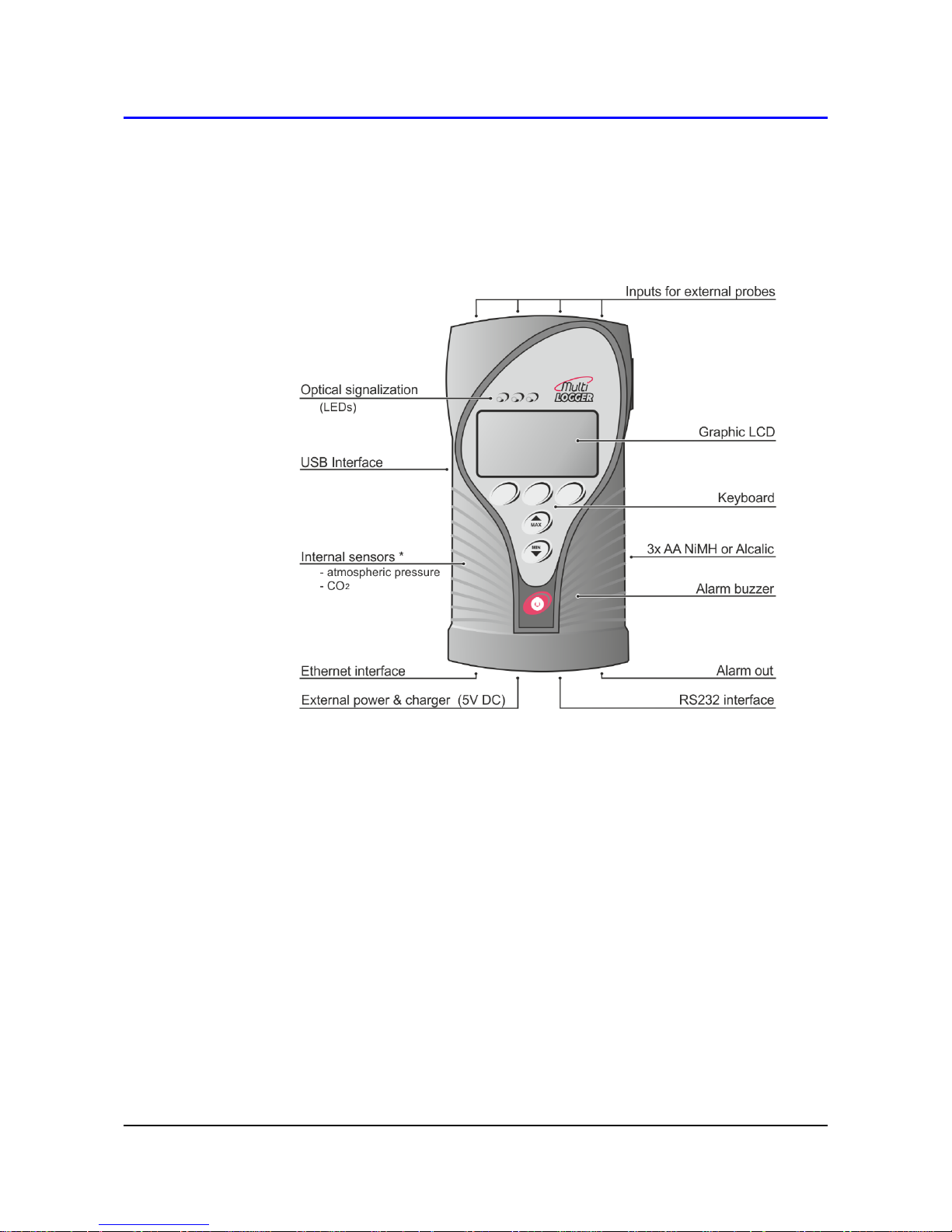
Multilogger drawing:
* only certain models
Page 6

6 IE-MLG-M1xxx-07
General safety precautions
The following list of precautions serves to reduce risk of injury or damage of
described instrument. To prevent injuries use instrument accordingly with
rules in this manual.
Installation and service need to be performed by qualified
persons only.
Use a suitable power supply. Use power supplies only with a voltage
recommended by the manufacturer (+5V DC) and approved in
accordance with proper standards. Pay attention, the source has
undamaged cables or cover.
The device and power supply must not be used in a humid and
hazardous environment (such as bathrooms), at locations exposed to
direct sunlight and to other heat sources, thus preventing damages and
deformation of the cover.
Do not use the instrument without its covers. Do not remove the
covers from the device.
Do not use the instrument if it does not work correctly. If you think,
that the device is not working correctly, let check it by qualified service
person.
Never charge batteries that are not rechargeable.
Do not use the device in explosive environment.
Page 7

IE-MLG-M1xxx-07 7
Getting started
Multilogger in portable application
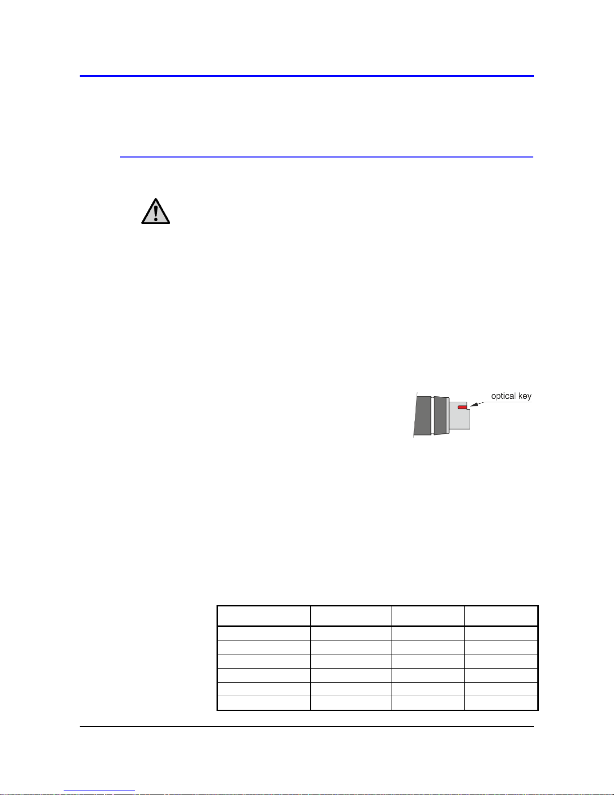
Connect the appropriate probes and signals to the device - for the
DigiS/M, DigiL/M and Pt1000/M probes, follow the optical key for correct
orientation of the connector. Probes of the DigiL/M-xx line with a cable
can placed in the holder on the side of device (optional accessory). For
more information, see Chapter “INPUTS OF MULTILOGGER”.
Switch on the Multilogger - push the switch button on the device. The
display lights and the instrument starts working. If you will communicate
with PC via the Ethernet interface, the power adapter +5V DC is
necessary (supplied accessories). For more information, see Chapter
“POWER SUPPLY OF MULTILOGGER”.
Install Comet Vision software to your computer - it is available at
www.cometsystem.com. If you purchased a license for full version,
register it.
Connect Multilogger with your PC - you can use the USB, Ethernet or
RS232 port (special cable necessary). The external power supply is
needed for Ethernet interface communication. For more information, see
Chapter “CONNECTING WITH THE COMPUTER”.
Device settings - use SW to set up the device in accordance with the
connected probes and your requirements. If you are not going to use the
device soon, turn it off and place it in its transportation case. For more
information, see Chapter “DEVICE SETUP USING SOFTWARE”.
Measurements - remove the Multilogger from the transportation case,
connect probes and external power adapter (if needed) and turn the
device on. Some device settings can be changed from its keyboard. When
measurement ends, move the device to your computer room and
download the recorded data to PC. For more information, see Chapter
“KEYBOARD OPERATION”.
Charging batteries - if the Multilogger includes rechargeable batteries,
you can recharge them when needed. For more information, see also
Chapter “POWER SUPPLY OF MULTILOGGER”.
Maintenance and periodic inspections - In order to secure reliable
operation of the device, it is recommended to make regular inspections. For
more information, see part “OPERATION AND MAINTENANCE
RECOMMENDATIONS”.
Page 8

8 IE-MLG-M1xxx-07
Multilogger in stationary application
Select a suitable location for placing of the Multilogger - pay attention
to parameters of ambient environment, minimize the number of cables,
avoid sources of interferences. For more information, see Chapter
“INSTALLATION INSTRUCTIONS”.
Mounting of sensors and routing of cables - pay attention to rules of
theirs installation, use recommended working positions, keep enough
distance from high power devices and cables.
Connect the appropriate probes and signals to the device - for the
DigiS/M, DigiL/M and Pt1000/M probes, follow the optical key for correct
orientation of the connector. Probes of the DigiL/M-xx line with a cable
can be placed in the holder on the side of device (optional accessory). For
more information, see Chapter “INPUTS OF MULTILOGGER”.
Check proper connection - before first switching on. If Multilogger
controls other action regulation elements, it is recommended to put them
out of operation before configuration of Multilogger.
Switch on the Multilogger - push the switch button on the device. The
display lights and the instrument starts working. If you will communicate
with PC via the Ethernet interface, the power adapter +5V DC is
necessary (supplied accessories). For more information, see Chapter
“POWER SUPPLY OF MULTILOGGER”.
Install the COMET Vision software to your computer - it is available at
www.cometsystem.com. If you purchased a license for the extended SW,
register it.
Connect Multilogger with your PC - you can use the USB, Ethernet or
RS232 port (special cable necessary). For Ethernet interface
communication the external power supply is needed. For more
information, see Chapter “CONNECTING WITH THE COMPUTER”.
Device settings - use COMET Vision software to set up the device in
accordance with the connected probes and your requirements. If needed,
check the alarms functionality. For more information, see Chapter
“DEVICE SETUP USING SOFTWARE”.
Maintenance and periodic inspections - In order to secure reliable
operation of the device, it is recommended to make regular checks. For
more information, see part “OPERATION AND MAINTENANCE
RECOMMENDATIONS”.
Page 9
IE-MLG-M1xxx-07 9
Installation instruction
Location of Multilogger must match the operating conditions and not allowed
manipulations.
Working position of the device:
Multilogger placed on a horizontal, nonflammable surface (horizontal
working position is not suitable for devices with thermocouple inputs and for
devices with cable-less probes).
Multilogger fixed on the wall from nonflammable materials or in a low-
current switchboard using the holder - the working position is with input
connectors upwards.
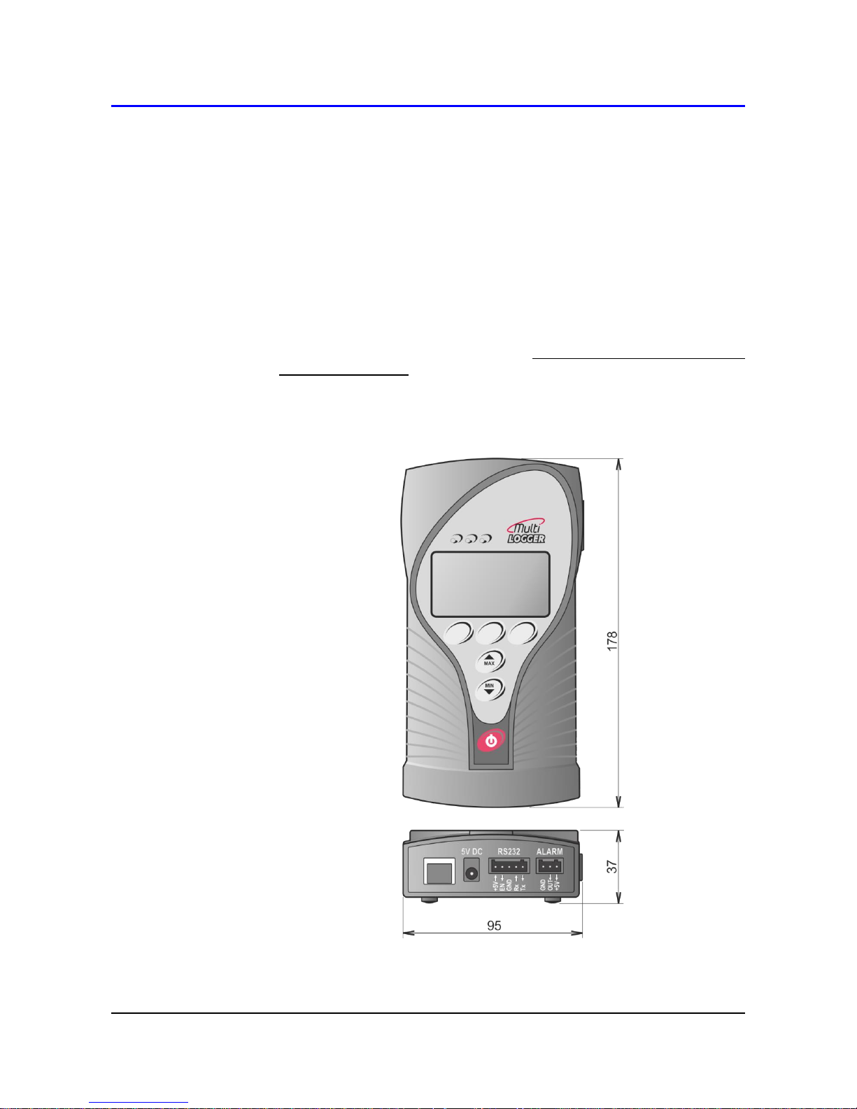
Device dimensions:
Page 10
10 IE-MLG-M1xxx-07
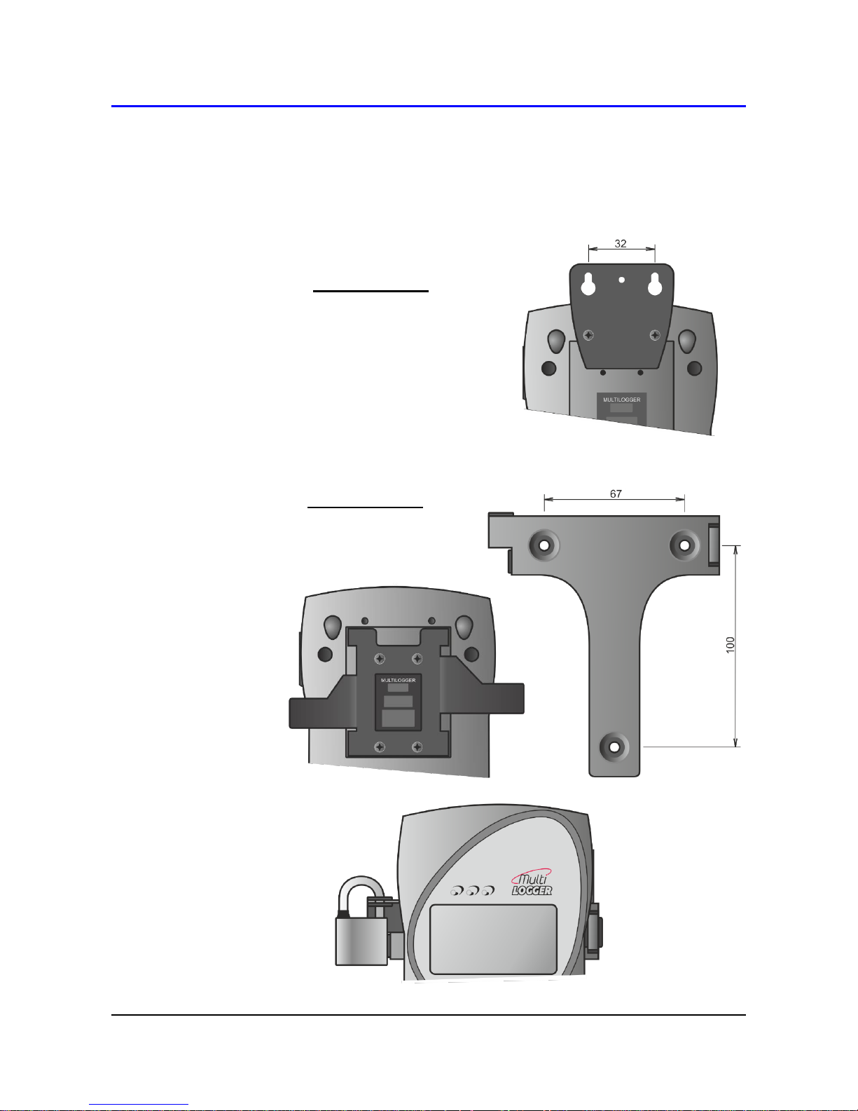
The way of mounting the holder to Multilogger and mounting holes
dimensions:
MLP001
MLP002
Page 11
IE-MLG-M1xxx-07 11
MLP004
Page 12
12 IE-MLG-M1xxx-07
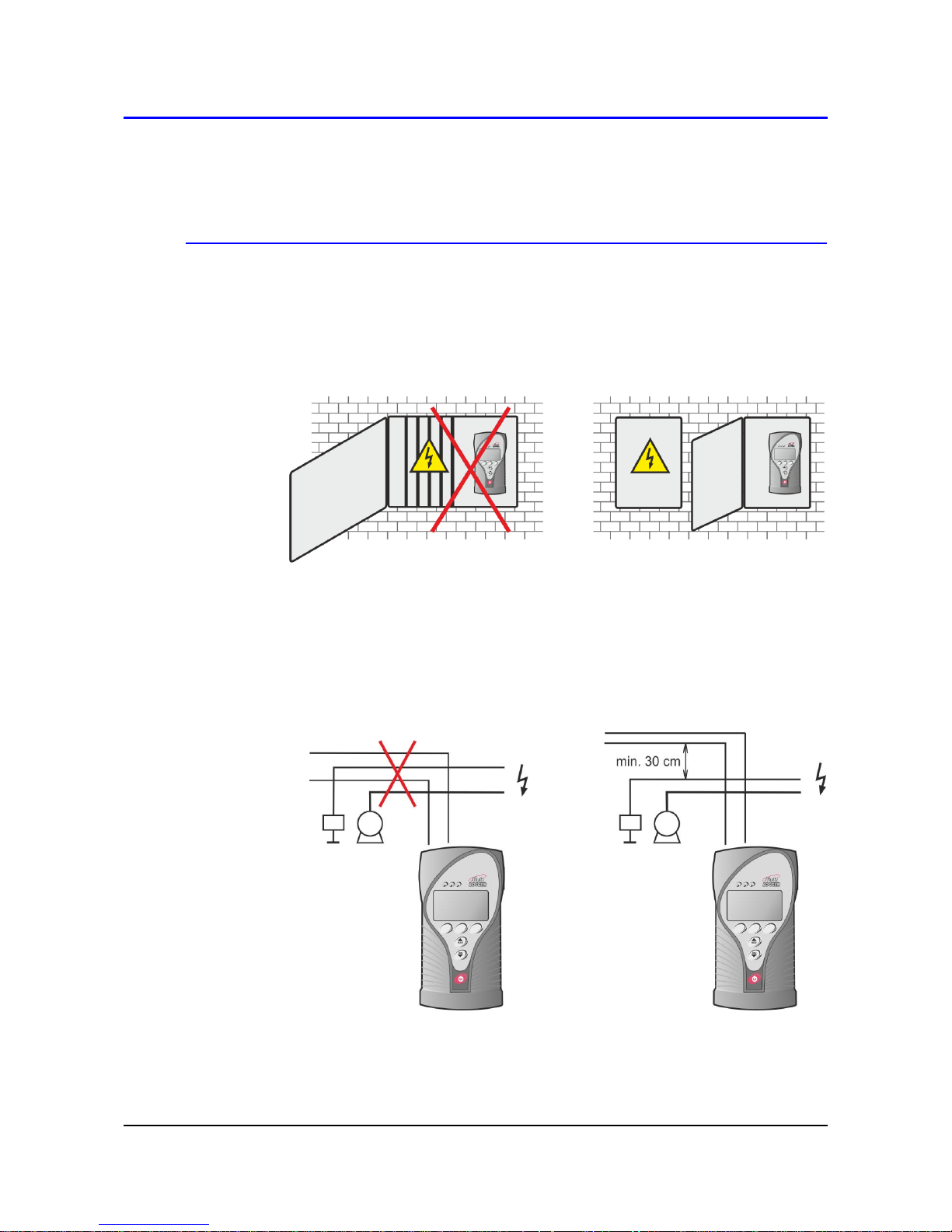
Recommendations for mounting
Do not mount Multilogger near sources of interference (Multilogger
must not be mounted directly to power switchboard nor to its nearness.
Also do not mount data logger near power contactors, motors, frequency
converters and other sources of strong interference).
In cable routing follow rules of standards for installation of low current
distribution (EN 50174-2), especially it is necessary to pay attention to
avoid electromagnetic interference intrusion to the leads, transmitters,
transducers and sensors. Do not locate cabling near sources of
interference.
Do not use leads in parallel with power distribution network leads
Page 13
IE-MLG-M1xxx-07 13
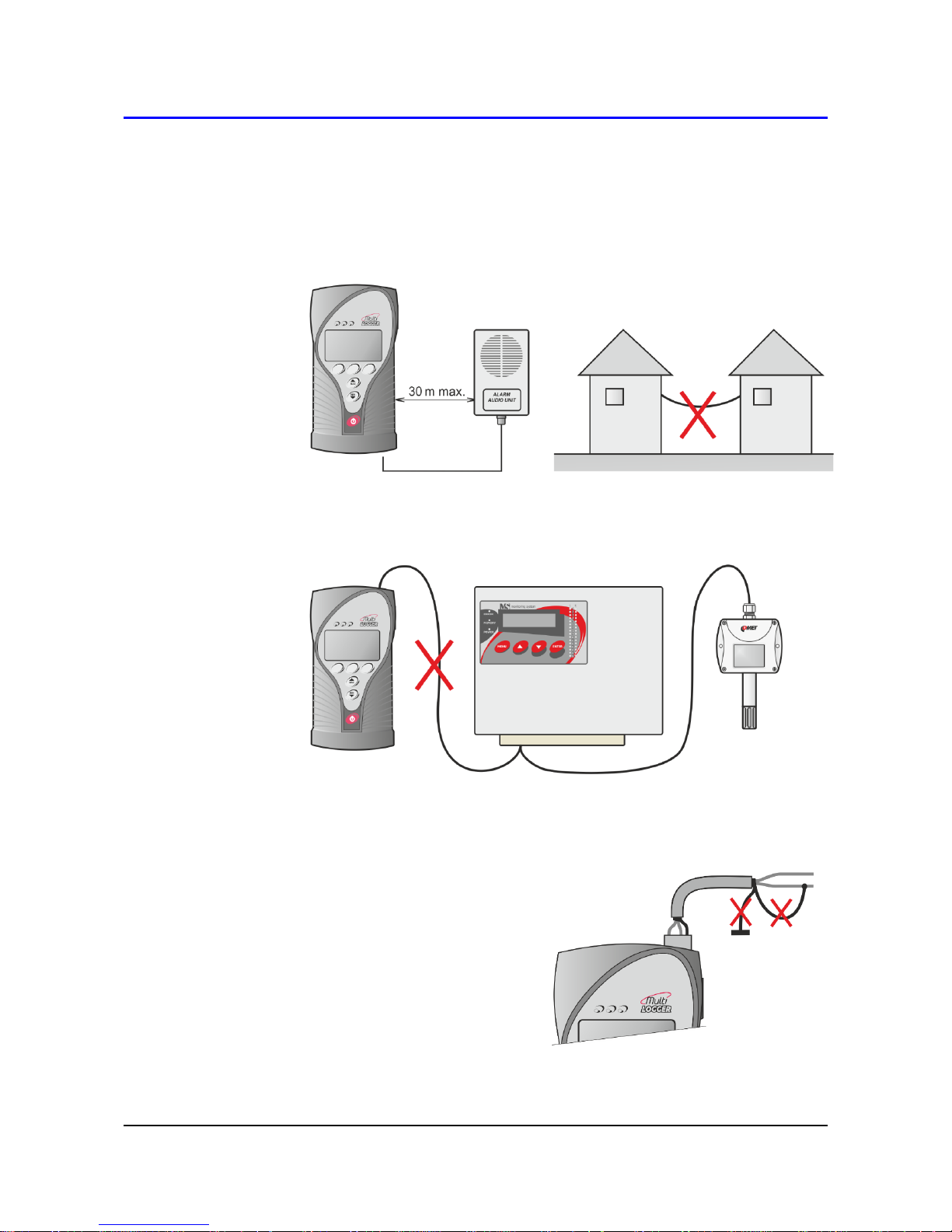
Do not use cables longer than 30 m generally; for RTD sensors is
recommended max. 15 m; cables must be installed only in interior areas.
Do not interconnect the inputs with other measuring systems.
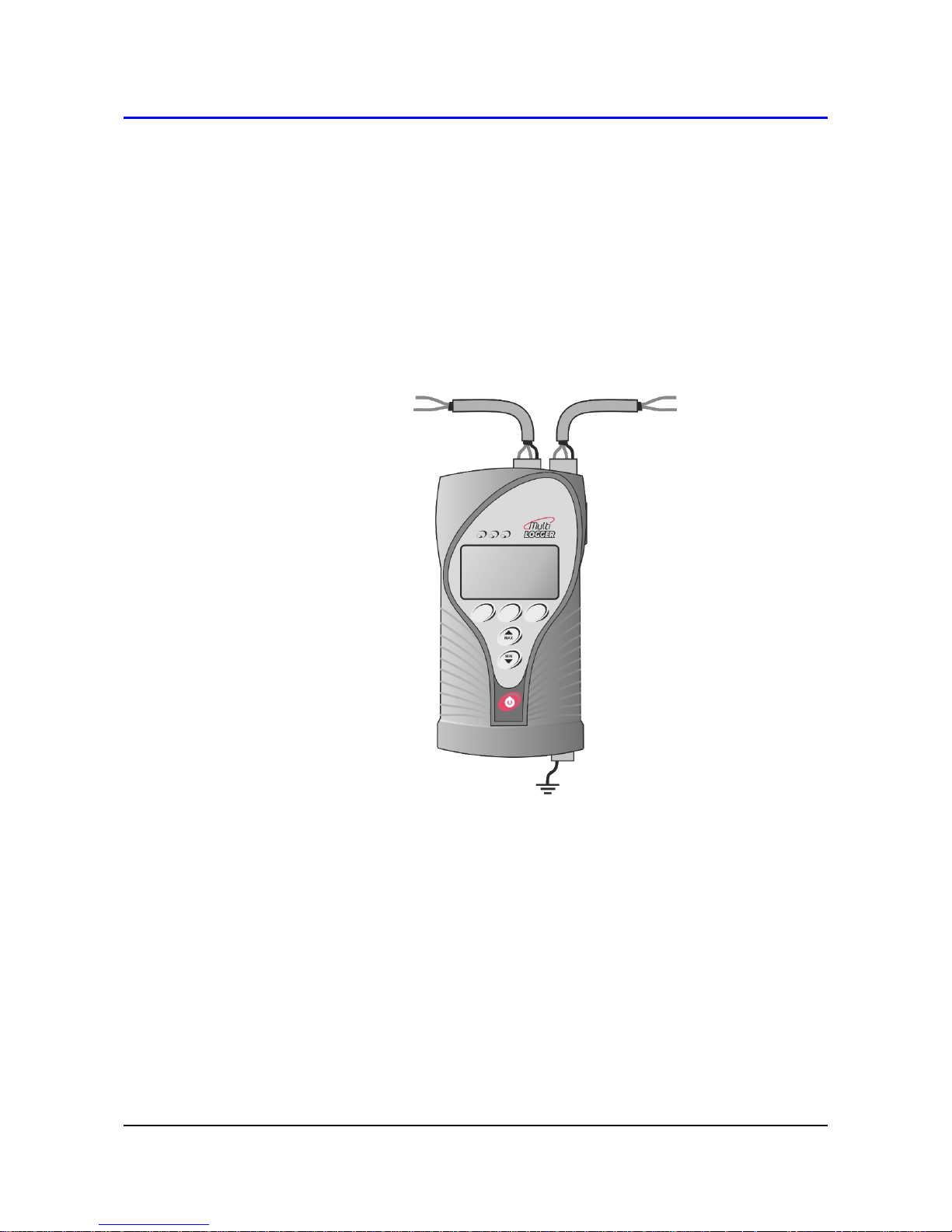
Use shielded cables for the voltage and current inputs - connect the
shielding to the Multilogger but not to the end devices if these do not have
a special terminal for it. In this
case, shielding must not be
connected to external metal
parts of this device or to any
other device. Never use
shielding as a signal wire.
Page 14
14 IE-MLG-M1xxx-07
Do not use common leads for several inputs.
It is recommended to earth larger systems with Multilogger at one
point - the GND terminal of the alarm output can be used for this purpose.
This grounding will work correctly if the system would not be grounded
currently at another point too. One-point grounded systems are more
resistant against electromagnetic disturbance.
Page 15
IE-MLG-M1xxx-07 15
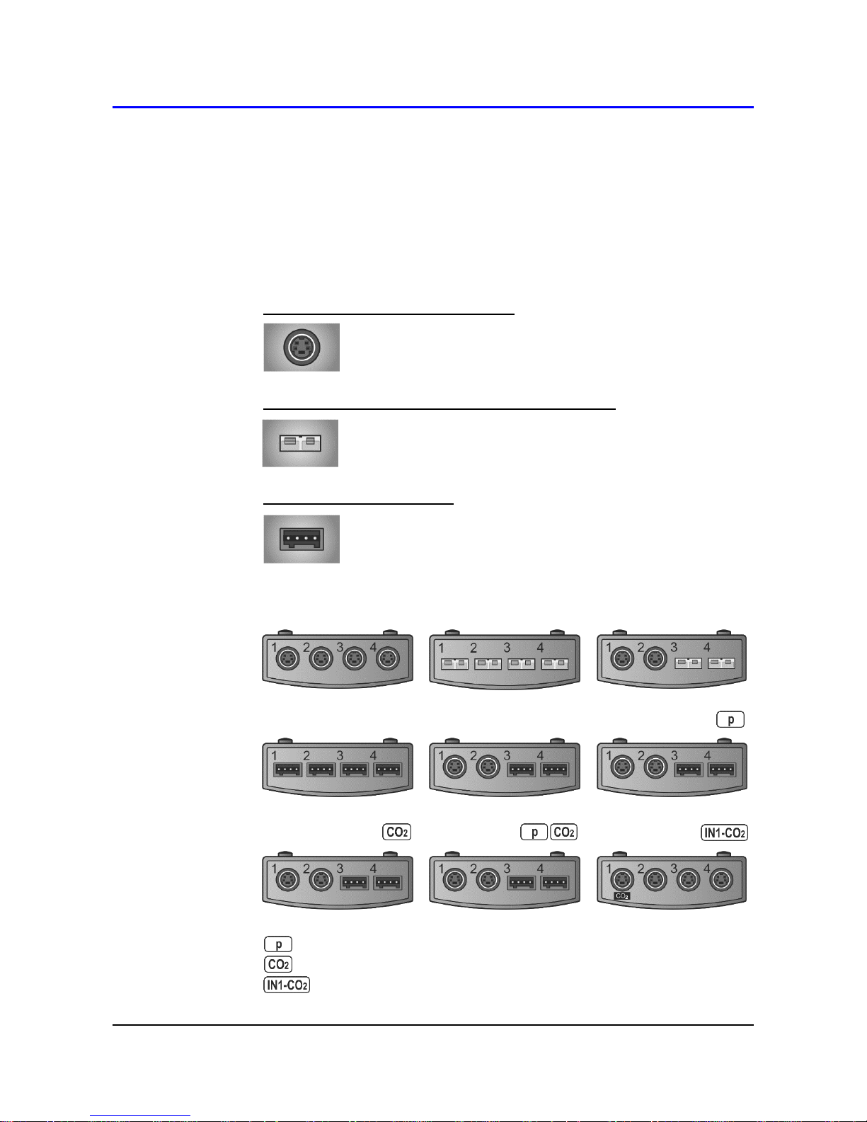
Inputs of Multilloger
Manufactured models differ from each other by their input ranges and by
input connectors. Prior to connecting voltage and current input signals, you
should check their parameters in the following part: “TECHNICAL
PARAMETERS OF THE MULTILOGGER INPUTS”.
Universal input with MiniDIN connector
temperature and humidity probe of Digi/M line
temperature probe of Pt1000/M line
temperature probe Pt1000 (custom RTD)
Universal input with miniature thermocouple connector
thermocouples of the K, J, S, B, T and N types
DC Voltage - 18 mV to +18 mV
DC Voltage - 60 mV to +140 mV
Universal input with terminals
DC current 0 to 20 mA
DC voltage 0 to 10 V
binary signals
M1140
M1200
M1220
M1300
M1320
M1321
M1322
M1323
M1440
Barometric pressure internal sensor
CO2 concentration internal sensor
CO2 external probe only
Page 16
16 IE-MLG-M1xxx-07
Input connectors
The Multilogger does not have galvanically isolated inputs. For this reason,
only devices that are not connected to any other circuit may be connected to
the inputs of Multilogger. Simplified circuit diagram of inputs is shown in
Appendix 3.
MiniDIN connector _______________________________
It is used for connecting the DigiS/M…, DigiL/M…, Pt1000/M probes
and for external CO2 probe. Plug properly oriented probe connector to
the input of Multilogger. You can follow the optical key for correct
position. Make sure that the wires, including their shielding, are not
connected to any other conductive parts! Universal MiniDin connectors
are designed for DigiS/M…, DigiL/M… or Pt1000/M probes.
Conventional (custom) probes with a Pt1000 sensor can also be
connected, however with certain
limitations (see Appendix 4). The
input connector marked “CO2” is not
universal and it is designed for
external CO2 probe only.
Universal thermocouple connector ___________________
Plug properly oriented connector to the input of Multilogger. The
connector is mechanically coded using a wider pin. Use the white
uncompensated connector for measuring voltage. Make sure that the
wires are not connected to any other conductive parts! Electrical
coupling among thermocouples can cause large measurement errors
or instable values! To obtain correct measurement values, the
Multilogger has to be temperature-stabilized!
Marking of subminiature thermocouple connectors and wires
manufactured by OMEGA (in accordance with US standard):
Thermocouple type
Connector color
+ wire color
- wire color
K (NiCr-Ni)
Yellow
Yellow
Red
J (Fe-Co)
Black
White
Red
S (Pt10%Rh-Pt)
Green
Black
Red
B (Pt30%Rh-Pt)
White
Black
Red
T (Cu-CuNi)
Blue
Blue
Red
N (NiCrSi-NiSiMg)
Orange
Orange
Red
Page 17

IE-MLG-M1xxx-07 17
Two voltage ranges are available on each
universal thermocouple connector for measuring
small voltages:
range -60 mV to +140 mV
range -18 mV to +18 mV
Use the white uncompensated connector
connected according to the picture.
Terminals ______________________________________
Inputs (0 to 20) mA, (0 to 10) V, binary inputs and the counter are
equipped with a two-part, self-locking WAGO terminal block. Insert flat-
bladed screwdriver to rectangle
terminal hole and push
screwdriver towards away from
you - contact is released. Insert
wire to released terminal (circular
hole behind the rectangular one)
and close the terminal by
removing the screwdriver.
The terminal block can be removed from the device without the need to
disconnect individual wires!
Connection of the binary and counter input:
Page 18

18 IE-MLG-M1xxx-07
Connection of the transmitter with voltage output:
Connection of the transmitter with the current output (active):
Connection of the transmitter with the current output (passive):
Page 19
IE-MLG-M1xxx-07 19
Alarm output
This output is accessible on terminals on the bottom side of the Multilogger.
Here are available these signals: OUT - open collector transistor, +5V power
supply from external power source and GND terminal (see also the diagram
in Appendix 2).
As the default, this output transistor is switched during selected alarms. It is
possible to set inverse behavior in the device's configuration (in this case
loss of external power supply acts as an alarm state). Activity of this output
can be canceled from the Multilogger keypad or remotely from a PC or web.
Remember to set a suitable alarms delay to prevent false activity of this
output.
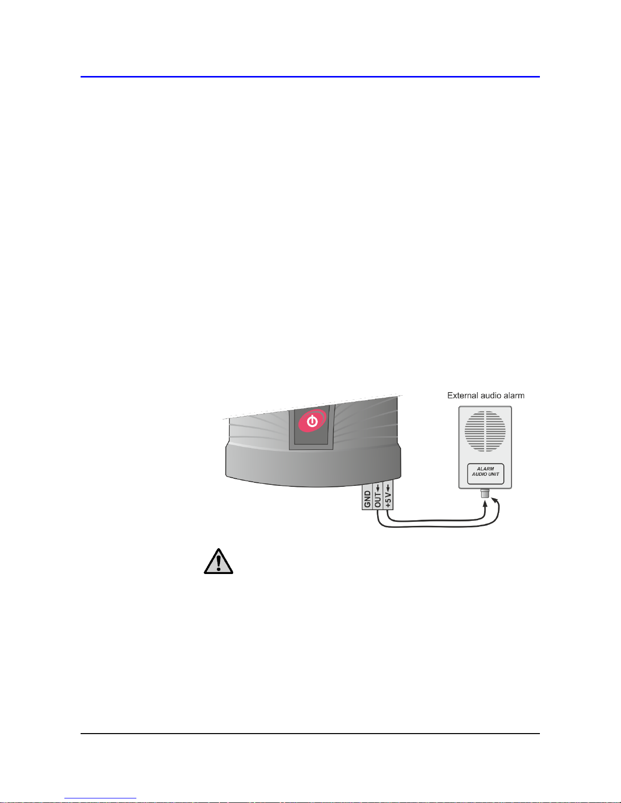
It is possible to connect to this output:
External audio alarm (optional accessory MP026) - connect the +5 V
terminal with the central lead of the CINCH connector of the audio alarm
unit and the OUT terminal with the outer lead of CINCH connector (see
the picture).
ATTENTION - the External audio alarm unit will not work if the
Multilogger does not have an external power supply.
Telephone dialer (optional accessory MP002) - in case of alarm
telephone dialer dials specified telephone number and announces voice
message. Connect the dialer according to its operation manual.
External alarm with its own power supply - make the connection
according to the following picture. Be careful do not exceed the maximum
allowed output current from OUT terminal (see the part Technical
Parameters). Use an external relay for higher currents.
Page 20

20 IE-MLG-M1xxx-07
Page 21
IE-MLG-M1xxx-07 21
Power supply of Multilogger
The Multilogger is powered from three AA batteries and optionally also from
an external +5 V DC power supply, which can be also used for charging the
batteries. A simplified schematics of the internal supply circuits is showed in
Appendix 2.
External power supply _____________________________
External power supply can be connected to the Multilogger in
several ways:
a) to the power supply connector on the bottom of Multilogger
(for example, AC adapter included in basic accessories)
b) to the terminal block of the RS232 interface (+5 V and GND
terminals)
c) via USB cable connected to PC (it will work only if the USB
port of the PC has current sufficiency to power the
Multilogger)
No energy from the batteries is discharged if external source is
present.
The Ethernet interface works only if an external power source is
connected. Some limited functions of this interface may also be
available during battery operation.
ATTENTION - never connect voltage greater than 5.5 V to
the external power supply input - it could damage the
device.
Batteries _______________________________________
The new Multilogger is equipped with high-quality NiMH
rechargeable batteries; the device is preset to intelligent algorithm
to their continuous charging if external power is present.
ATTENTION - if you insert the non-rechargeable batteries
to the Multilogger, change the battery model to Alkaline in
the device configuration. Never charge batteries that are
not rechargeabled!
Charging batteries:
a) batteries can be charged if an external power source is
connected
Page 22

22 IE-MLG-M1xxx-07
b) the charging process will start if the NiMH charging
accumulators are selected in the device configuration
c) when the Multilogger is turned off, the batteries cannot be
charged
d) the Multilogger allows for two battery charging modes -
high current fast charging mode and low current slow
charging mode
Slow low current charging mode is mainly used for stationary
installations. Batteries work as a backup source in case of
external power failure. Charging is automatically activated
after restoring of external power supply. During slow charging
device operates normally. Recharging of completely
discharged battery takes several days, however, in normal
operation, do not expect a completely discharged battery. The
charging process is indicated on the device display using the
corresponding symbol .
Fast high current charging mode is mainly used for portable
applications. Discharged batteries can be recharged within a
few hours. The charging procedure has to be activated by the
service personnel:
a) If the Multilogger is on, switch it off. Connect an external
power supply to the device.
b) Press down and hold (approximately 3 seconds) the red
On/Off key on the Multilogger until you see “NiMH charger”
on the device display. The charging process is started.
c) During fast charging Multilogger does not work in the
normal operating mode, does not take measurements and
does not communicate with the PC.
d) Once the charging process is completed, the Multilogger
displays the “Batteries charged” message and you can turn
it off.
e) The charging can be proceed within a temperature range
of 0 °C to +40 °C only. If the temperature is out of this
range, the charging process is automatically stopped.
Page 23

IE-MLG-M1xxx-07 23
Battery replacement:
If you want to keep the correct time setting in your device,
do not let the battery discharge completely.
When replacing the battery, do it quickly. The timer circuit
runs without battery for max. 5 minutes if the device is
switched off.
a) Switch the Multilogger off.
b) Remove the battery cover, take out the old batteries and
insert new batteries (take care for correct polarity). Battery
polarity is shown on its holder.
c) Switch the Multilogger on and make sure the set time is
correct (device menu View settings - General settings).
d) If you change the battery chemistry (rechargeable <=> non-
rechargeable), you have to make this change in the device
configuration also.
Note: The Multilogger can operate with removed batteries
powered externally. This is not a standard use of the device
but it is possible. In this case, the full battery is displayed.
Interruption of power supply causes loss of time setting.
Page 24

24 IE-MLG-M1xxx-07
Keyboard operation
Control and indication parts
The front panel of the Multilogger includes 6 keys, 3 indication LED diodes
and a graphic display.
The red key with the switch symbol is used for Multilogger turning on/ off.
The MIN/MAX keys (with the arrows) are used for quick show of the
minimal and maximal measured values and also for moving through menu
items. Function of keyboard upper row buttons is defined by actual
description of each button on the lower LCD line display.
The indication LED diodes inform us about the current state of alarms and
allows the operation personnel to observe this important information even
under low light and from a greater distance.
green LED no active alarms, “everything is OK”
orange LED one alarm is active
red LED several alarms are active or a system alarm
(device malfunction)
The green LED (“everything is OK”) can be deactivated in device
configuration to save energy. The indication LEDs can be enabled
permanently or can be set to a blinking mode in battery mode to save
energy also. If the measured quantity has both alarms set into the same
direction, the LED diodes will indicate the current level of value: green everything is OK, orange - exceeding the lower limit, red - exceeding the
upper limit.
The LEDs show an overview about all active alarms in the Multilogger. In
the device configuration, we can assign individual alarms to the LED
diodes for customizing the indication to our needs.
Page 25

IE-MLG-M1xxx-07 25
Basic display operation
Current measured values (or min/max) and their units are shown on the
device display. To make it easier, the short description of measured quantity,
the corresponding input number or a user description of the input, can be
optionally displayed. Using the VIEW multifunction key, you can switch
among these views on the display. You can choose from 3 different display
options: input number + short description of measured quantity, input number
without the short description of measured quantity and channel number +
short description of measured quantity. If the Multilogger setup allows it,
audio signaling of the currently active alarms can be temporarily muted using
the MUTE multifunction key.
Numerical values of the measured quantities can be optionally displayed in
three different font sizes according to user needs. When the smallest font
size is selected, up to 6 quantities can be displayed together. When the
largest font size is selected, the maximum number of the quantities that can
be displayed together is 2. The maximum range of numerical values on the
display is 7 characters (including the decimal point and sign "minus").
Exceeding this range is indicated as several dashes (------), recording,
however, is still running correctly.
When the Multilogger is set for measuring more quantities or calculated
channels, their viewing can be cyclically switched using the multifunction
CHANN key. The order of the displayed quantities can be modified as
needed.
The bell icon on the line of the measured value indicates an active alarm for
this quantity.
The status line of the display shows icons that indicate the current status or
device mode:
full memory of non-cyclic record
active recording
Page 26

26 IE-MLG-M1xxx-07
active recording of analog values (in the “during alarm
only” or “controlled by an external input” recording modes)
inactive recording of analog values (in the “during alarm
only” or “controlled by an external input” recording modes)
external power supply present (if the status line is
occupied by icons of a higher priority, it is not displayed)
minimal measured values are displays
maximum measured values are displays
approximately one half of the battery capacity remaining
battery is discharged, it needs to be replaced (alkaline
batteries) or recharged (NiMH accumulators)
battery charging in progress
the data memory limit exceeded
low voltage of the real time clock circuit detected, the time
could be incorrect!
alarm at least on one channel (the particular channel is
marked with a bell by the given value)
system alarm (alarm sources can be found in the System
information menu)
downloading of recorded data in progress (it is not
displayed for MIN/MAX view mode)
the Multilogger is being configured from a PC or via the
web (it is not displayed for MIN/MAX view mode)
Page 27

IE-MLG-M1xxx-07 27
Main menu
Some device settings can be viewed or modified directly on the device using
the keyboard.
Main menu items: 1. System Information
2. Viewing settings
3. Change the Display
4. Device Settings
5. Clear Min/Max
6. Clear Latched alarm
7. Device information
1. System information _____________________________
This menu item shows information that does not a part of device
configuration and that describes the current status of the Multilogger:
System alarm sources specify, what problem has caused the alarm,
indicated by icon on the display.
a) The dash next to the item description means that this item
is not enabled for evaluation in the device configuration.
b) The tick next to the item description means that this item
is enabled in the device configuration and that it is OK.
c) The exclamation mark next to the item description means
that this item is enabled in the device configuration,
however, it is not associated to the LED, audio or alarm
signal indication and it is in error state.
d) The bell next to the item description means that this item
is enabled in the device configuration, and it is associated
to the LED, audio or alarm signal indication and it is in error
state.
System information items:
a) Remaining battery capacity (0-100%).
b) Data memory occupation in %.
Page 28

28 IE-MLG-M1xxx-07
c) Real time clock circuit state: tick - OK, exclamation mark
- low voltage of the real time clock circuit detected, the time
could be incorrect!
d) Activities of the Alarm out signal: tick - active, field without
a tick - inactive.
e) MUTE activated: tick - was activated (alarm is still active),
field without a tick - was not activated (or the alarm is
inactive).
f) Activities of EN signal: tick - active, field without a tick -
inactive.
g) battery voltage: range from 3.4 V (completely discharged
battery) to 4.5 V (new or just charged battery)
h) device internal temperature (affects the battery charging)
i) cold junction temperature of the thermocouples (only for
models with a thermocouple connector)
j) Multilogger firmware version.
2. Viewing settings _______________________________
Allows to view the following settings:
record settings (recording interval, cyclic record, record on alarm,
record of the average and min/max values per logging interval)
general settings (LCD backlight intensity, battery type, menu
language, date and time in the device)
alarm limits (limit values, hysteresis and delay for each existing
channel and alarm. You can change channels using the arrow
keys).
alarms indication - information about settings of alarm
signalization (optical, audio, Alarm Out) and if it is enabled to
temporarily deactivate the alarm signalization (MUTE function)
memory occupation - information about alarm limit of data memory
occupation and signalization of this alarm (optical, audio, Alarm out
signal)
Ethernet interface - information about LAN parameters (device IP
address, gateway IP address, network mask, IP address of the DNS
server)
Page 29

IE-MLG-M1xxx-07 29
3. Display settings _______________________________
Allows to set the parameters of the displaying:
Font size (large, medium, small)
Displaying input description of the measured quantity (yes, no)
Order of the displayed channels (based on the input number, based
on the channel number, selection)
4. Device Settings ________________________________
Access to this submenu can be protected by a PIN1 code. Recording
is stopped after entering into editing mode. If no key has been pressed
for 5 minutes in the editing mode, the device restarts with the last
settings. The following parameters can be edited:
recording parameters (recording interval, start/stop recording)
general settings (LCD backlight activity&intensity, battery type,
menu language)
alarm limits (limit values and alarms directions can be set for each
existing channel and alarm. You can switch from one channel to
another using the arrow keys).
alarm indication - enable or disable of alarm signalization (optical,
audio, Alarm out signal). Setup of MUTE function - temporary
deactivation of audio and/or Alarm out signalization.
memory occupation - limit and signalization (optical, audio, Alarm
out signal)
Ethernet interface - network parameters (device IP address,
gateway IP address, network mask, IP address of the DNS server)
5. Erase Min/Max ________________________________
Erase of the Min/Max memory of either all measured quantities (“All
channels” option) or selected measured quantities (“Individual
channels” option) by the user. This function can be protected using
PIN2.
The Min/Max values will be erased automatically if the device happens
to be without any power supply, for example, when replacing its
batteries.
Page 30

30 IE-MLG-M1xxx-07
6. Deactivation of Latched alarm ____________________
If the “Latched alarms” function is enabled in the device configuration,
the active alarms are not reset when the measured values return back
to the allowed limits. Instead, they remain active until they are
deactivated by the user. They thus warn us that “something was
happening” during the monitored period, i.e. that the alarm limits were
exceeded. This function can be protected using PIN2.
7. Device information ____________________________
The 32-character user description of the Multilogger, device model and
its serial number are displayed here. The next screen displays a
summary of the configuration of individual inputs.
Page 31

IE-MLG-M1xxx-07 31
Connecting with the computer
You can connect the Multilogger to the computer through the following
communication interfaces:
USB - fast connection for short distances (up to 5 m, communication
speed of 460,800 Bd). Connect the device to the computer using the
supplied cable, launch the SW and add Multilogger to the list of your
Comet devices.
RS232 - slow connection for distances of up to 15 m, designated mainly
for communication via GPRS modems (communication speed of 115,200
Bd / 230,400 Bd).
Ethernet - fast connection for long distances. An external power supply
source has to be connected to the Multilogger (for example, a power
supply adapter). The device IP address is preset to 192.168.1.78, the
default sub-net mask is used as well as port 10001 (we recommend not
changing the port number if it is not necessary).
Configuration:
a) Verify if you can use the preset IP address with your
network administrator. If not, obtain a new IP address,
network mask, gateway address and address of the DNS
server from him/her.
b) Set these parameters on the Multilogger (Menu - Device
settings - Ethernet interface). Alternatively, you can
connect the Multilogger via USB interface and do the above
stated configuration using the COMET Vision software.
c) Connect the Multilogger into your LAN (Ethernet cable is
not included as device accessory).
d) Launch the COMET Vision software and add the
Multilogger to the list of your Comet devices.
The Multilogger automatically identifies which communication interface is
connected and will use it for communication. When multiple interfaces are
connected, USB has the highest priority and Ethernet the lowest. For
example, if Multilogger has to work over Ethernet, no USB or RS232 interface
can be connected to the device.
ATTENTION - we recommend using the supplied power adapter
for battery charging. When you use a USB charger, the
Multilogger may not communicate when the charger is
connected!
Page 32

32 IE-MLG-M1xxx-07
Software COMET Vision
Hardware and system requirements _________________
the Windows 7 and later or the Windows Server 2008 R2 and later
operating system
1.4 GHz processor
RAM 1 GB
Program description ______________________________
The COMET Vision software can be used for device configuration and
for obtaining recorded data and currently measured values. The device
can be connected via USB, Ethernet or a serial port.
The program is available for free (at www.cometsytem.com) or as a
paid version. The free version allows work with one device at the same
time and contains the basic functions only. The paid version lets you
connect any number of devices that can work simultaneously (for
example, downloading data from several devices at the same time,
having multiple displays launched, etc.) and will also give you access
to advance functions (for example, charts, statistical overview of the
recorded data, custom display, export to the database, etc.).
Adding the Multilogger to the list of Comet devices ______
The device can be added by clicking on the “add device” button (you
can find it under the “Welcome” menu, which is displayed upon the first
launch of the program, or also under the “Home page of the device”
menu, under the “Devices” option). A menu with a selection of
connection types is displayed (USB, Ethernet, Serial); for USB and
Ethernet, you can select device from the list of offered devices; for
serial line, you have to select a communication port, to which the device
is connected. Finally, confirm you selection using the “Finish” button
and the device will be added.
Automatic detection can be used for devices connected via USB. Once
the device is connected to your computer, the device is automatically
added to the list of Comet devices (within about 5 seconds - time
necessary for the device initialization).
When connecting device via USB the baudrate is 460,800 Bd, while
RS232 the baudrate is 115,200 Bd.
Page 33

IE-MLG-M1xxx-07 33
How to work with the program ______________________
The main menu of the program is on the right side with items: “Home”,
“Devices”, “Files” and “Online Displays”. These components control
appearing bookmarks. Each item has its bookmarks, one of them
named “Home” is similar for all items. The other options are specific for
each item.
Page 34

34 IE-MLG-M1xxx-07
Device setup using software
Upon being the Multilogger switched on using the red button, the device
begins to take measurements and to record and evaluate alarms according
its user configuration. Complete configuration of the device can be done
using the COMET Vision software. Some parameters can be changed from
the device keyboard or from its web pages. When editing the Multilogger
configuration, the device normally works, however, access to some of its
functions is limited (downloading records, editing of the device configuration
by other users).
Device configuration basics
Connect the Multilogger with your computer and launch the
COMET Vision software.
If the software not communicated with this device yet, add Multilogger to
the list of your Comet devices. For more information see part
“CONNECTING THE MULTILLOGER WITH THE COMPUTER”.
If the Multilogger is correctly connected, the Device Home panel displays
its current status.
Click on the Configuration button. The device configuration is loaded and
you can view or edit it.
When you make a configuration change of any items, the SW goes to the
editing mode and limits the device access for other users now.
Upon a long user inactivity period, the editing configuration mode is
automatically terminated.
Finally, save the new configuration to the Multilogger (Apply changes).
Device configuration items
General - Information _____________________________
Here are displayed the basic information about the connected
Multilogger. It includes its name (Device name), which is used for
identifying your device and its measured values. The instrument can
be named according to of its application or you can use the default
name. The maximal length of the Device name is 32 characters - use
letters, numbers, underscore characters, etc. Moreover, this panel
states the serial number, model name and firmware version.
Page 35

IE-MLG-M1xxx-07 35
General - Preferences ____________________________
Here you can select language localization Language on the device
terminal, Default temperature unit °C/°F and, for some models,
Atmospheric pressure unit. If your model does not measure
atmospheric pressure but it is necessary to know it (for calculated
humidity values and CO2 concentration), you need to specify Ambient
average pressure.
For barometers, you can enter a correction constant for sea level
recalculation as the actual sea level pressure or altitude. Actual sea
level pressure can be obtained from, for example, nearby observatory
or nearby weather station.
General - Date and Time __________________________
Here you can set the date and time in Multilogger (Date and Time). In
the device is running the local time. Use TimeZone, if you can
determine its relation to UTC. This information will be available for all
timestamps from the device (record, online monitoring). The
Multilogger does not allow for automatic changes between the summer
and winter times.
ATTENTION - after change the date and time, the
recorded data in the Multilogger will have to be deleted!
General - Advanced - Energy ______________________
The Multilogger running in the standard mode will measure all inputs
once per second (with the exception of measuring CO2 concentration,
which will be measured every 2 minutes). The advantage is a fast
response of the device, the disadvantage is its higher current
consumption if the device is powered from batteries only. If you operate
the Multilogger from batteries for a long time and you do not need a
fast response time, you can use the energy saving mode (Energy
saving mode), under which the device consumption from the batteries
will significantly decrease, however, the measurement interval will be
extended to 10 seconds (10 minutes for CO2 concentration).
Consumption details can be found in the Technical Information.
Page 36

36 IE-MLG-M1xxx-07
General - Advanced - Device start ___________________
Here you can disable the “Off key” of the device.
General - Advanced - LCD Display __________________
These settings are used for optimizing the backlight of the display in
relation to your application. As a default, the Multilogger is set in a way
that the backlight (LCD backlight activity) is activated only for several
seconds upon the last key pressing. If, however, you need to ensure a
good visibility of the display in the mains powered fixed installation, turn
on the backlight activity only when the external power supply is on and
choose a suitable intensity (LCD backlight intensity). If the backlight is
permanently turned on while Multilogger is powered from the batteries,
they discharge relatively fast, therefore do not use this setting. Turn
the backlight off for applications, for which is required the longest
battery life.
General - Advanced - Peripherals ___________________
There you can set the activity interval and baudrate of the external
GPRS modem, which is connected to the RS232 interface of the
Multilogger. In addition, there can be set power management of the
Ethernet interface.
If you set the interval of the turn-on procedure of the GPRS modem,
the Ethernet interface of the Multilogger will be deactivated.
Ethernet in battery mode
The Ethernet interface does not work without external power supply.
However, this interface can send a warning e-mails and records to the
database using DataLink protocol in the battery mode if you turn on this
feature. These messages will be sent immediately after power failure
or on new alarm. Additionally, they can be sent repeatedly at the
specified interval.
Warning – Ethernet interface in battery mode significantly reduces
usable battery capacity. If your LAN is not backed up do not use this
options.
Page 37

IE-MLG-M1xxx-07 37
Record ________________________________________
This options are used for controlling the record functions of the
Multilogger. Recording can be turned on and off as needed (Recording
On/Off). However, if the record is turned off and then you turn it on
again, this takes up 0.1% of the free memory capacity. Use the Cyclic
record if you require the device to continue the recording even when
the data memory is completely full. In this case, the oldest data are
replaced by new ones. If you do not use this option, the recording will
stop once the memory is full. Another important parameter is the
Recording interval. It can be set from 1 second to 24 hours (see the
Technical Information). The recording is performed in integral multiples
of a set interval. For example, if you turn the device on at 5:05 a.m. and
if you have set the logging interval at 1 hour, the first data will be
recorded at 6:00 a.m., next ones at 7:00 a.m., etc.
Recording can be continuous or, alternatively, records can be taken
only if any measured quantity is in the alarm state (the system alarms
does not trigger recording). Moreover, Multilogger with binary input No.
3 also offer the option to control the recording by the status of this
binary input. These settings can be performed in the section Recording
mode.
By default, the device records the actual values at the time of the
recording interval. However, if continuous recording is on (see above),
you can select recording of average, minimal and maximal values
during recording interval. These settings can be performed in the
section Recorded values.
The last thing to do when configuring the recording is to select the
measured quantities that you want to record (see the Inputs panel
described below).
ATTENTION - upon changing cyclic non-cyclic
recording, you will need to erase all the recorded data
saved in the device!
Alarm events - Signalization ________________________
The Multilogger allows to evaluate alarm states, which can come from
the measured quantities or which can signalize some device problem
(exceeding of the data memory occupation limit, system alarms). For
each alarm it is possible to assign the method of their signaling to the
user.
Page 38

38 IE-MLG-M1xxx-07
Alarms can be signaled using the LED diodes directly on the
Multilogger (Optical signalization - LED). Since the Multilogger can
work in the battery mode, additional options are available for
minimizing the current consumption. For a state without an alarm can
be selected green LED indication. When the device is powered from
batteries, you can select more energy economical mode, under which
the LED diodes only shortly blink in the case of an alarm.
In addition, the alarm can be signaled acoustically with characteristic
sound that is repeated at regular interval. Service personnel can easily
confirm the audio signal and thus make it silent until a new alarm
occurs. These settings can be performed in the section Mute of
signalization.
Alarm signaling can be also performed using the ALARM OUT output.
Upon an alarm, the Multilogger can switch on the open collector
transistor of this output in accordance with the description in Chapter
“ALARM OUTPUT”. This transistor can be optionally switched on or
switched off when there is an alarm. The Mute function can be also
used for this output.
Alarm events - Preferences ________________________
In the standard mode, the alarm exists if the measured value is out of
limits, and the alarm becomes inactive if the measured value returns to
its limits. In some cases it is suitable that the user, who comes to the
device after a longer period of time, can easily make sure that no alarm
has occurred while he/she was gone. If you activate the Latched alarms
option, all alarms that occur in the Multilogger will remain active until
the service personnel is not confirmed them.
Here you can also allow remote erasing of the alarm memory and
remote deactivation of alarm signalization from the software
COMET Vision or from the web (Remote Mute & Erase of Latched
alarms); moreover, you can permit or forbid alarm deactivation from the
device keyboard (Local Mute enabled). To protect access to these
functions, you can use the PIN2 code (Security panel).
Furthermore, you can allow alarm evaluation here only on certain days
of the week and within defined range of hours per day. It is not suitable
to combine this setup with the above described Latched alarms option.
Page 39

IE-MLG-M1xxx-07 39
Alarm events - Mute of signalization _________________
The Mute function is used for deactivating alarm signalization by the
user. It can be optionally applied to audio signalization, the ALARM
OUT output or both. It can be performed from the keyboard, from the
web or from the software COMET Vision. To protect access to these
functions, you can use the PIN2 code, which the operation personnel
must enter. This function deactivates enabled alarm signalizations until
a new alarm occurs. The deactivation can be permanent (until a new
alarm occurs) or temporary (if the alarms remain active even after
selected time out, the signalization is restored).
Alarm events - Memory occupation __________________
If you need to indicate exceeding of your specified limit of the data
memory occupation, use the setup in this section. The signalization can
be selected as optical (red LED diode), audio, or by the means of the
ALARM OUT output activation or sending email to selected recipients.
Alarm events - System failure ______________________
The options in this section allow for setting up the System alarms which
respond to the Multilogger or probes malfunction. The signalization can
be selected as optical (red LED diode), audio, or by the means of the
ALARM OUT output activation or sending email to selected recipients.
The Multilogger can respond to the following states:
a) Measurement error on any channel ... for example, a
disconnected or damaged probe
b) Device configuration error ... an unexpected device
configuration error
c) Selftest error ... empty battery
d) External power lost ... failure of the external power supply
source
Page 40

40 IE-MLG-M1xxx-07
Security ________________________________________
The Multilogger allows an easy security option by the means of PIN
codes:
PIN1: protection against unauthorized changes of the device
configuration (from a PC or device keyboard), erasing
of data memory and counter erasing
PIN2: protection against unauthorized alarm deactivation
(Mute), confirmation of alarm memory (Latched
alarms) and erasing of the Min/Max values
Ethernet - General _______________________________
Here, you can make the basic connection setup of the Ethernet
interface. To obtain some information, you will need to contact your
computer network administrator. First of all, you have to find out if you
are going to use a fixed IP address or if it will be assigned by the DHCP
server in your network. Based on the answer, select the appropriate
option (Obtain an IP address automatically - DHCP). If you do not use
DHCP, enter a unique IP address of the Multilogger, assigned to it by
your network administrator (IP address). By default, the device address
is set at 192.168.1.78. Keep the port number (Port) at 10001, unless
you have a reason to change it. If communication is performed between
different network segments, you need to enter the gateway address
(Default gateway). If you use domain names instead of IP addresses
in some of the following setups, you have to enter the IP address of
your DNS server (DNS Server IP). Under standard networks use the
default Subnet mask, which is set automatically pursuant to class A, B
or C. If you use a network with a non-standard range, the mask have
to be entered manually. You usually do not have to change the size of
the block transmitted through the network (MTU size), thus keeping it
at 1,400 bytes.
External power supply is required for full operation of the
Ethernet interface. Some limited functions of this interface may be
available for battery operation. See part Device setup using software,
General - Advanced – Peripherals, Ethernet in battery mode options.
Page 41

IE-MLG-M1xxx-07 41
Ethernet - Email - General _________________________
Here you can do the basic email setup. If you want to use the sending
of warning emails on alarms, switch this function on (Email sending
ON). Next, set the IP address or SMTP server or its domain name
(SMTP Server), port (SMTP Server port) and, if the server requires
authentication, enter your login name and password (Autentication).
Continue by entering addresses of up to three recipients of the warning
emails (Email recipient #1 - #3) and, finally, enter the address of the
email sender (Sender). This is usually the same as the user name in
the SMTP authentication.
Ethernet - Email - Preferences _____________________
Here you can set further email parameters. If you want the Multilogger
to send the regular emails during the active alarm, enter of their interval
(Repeat alarm sending interval). If you enter 0, the email is sent only
upon the start activity of alarm and upon end its activity. Moreover, you
can set sending of a regular informative email, which informs the user
that the Multilogger is working properly (Keep alive email sending).
You can use shortened emails (Short email) especially for forwarding
them as SMS messages to mobile phones. You can also insert your
own comments to the emails: if the alarm appears (Alarm note), if the
alarm expires (Clear alarm note), in the case of system alarm (System
alarm note) and in the case of exceeding the memory occupation limit
(Memory overflow note).
Ethernet - Datalink _______________________________
The Datalink protocol is used for connecting the Multilogger with the
Comet database system. Connection to the server is opened by the
Multilogger in regular intervals. Further control of the communication is
then performed by the server. If you want to use this function, you have
to allow it (Datalink On). Next, enter the IP address or Datalink server
or its domain name (Datalink address), communication port number
(Datalink port, default is 10002), connection opening interval (Datalink
interval) and the database key (Datalink key). If you require to send the
irregular alarm messages using this protocol, you need to allow
asynchronous transmissions (Asynchronous communication).
Moreover, you can also set here the data downloading interval and
possibility of erasing recorded data in device.
Page 42

42 IE-MLG-M1xxx-07
Ethernet - Web __________________________________
The Multilogger has its own web pages, where you can monitor
currently measured values and alarm states, and where you can
change some configurations. First of all, you have to allow the website
option (Web pages On). If necessary, you can change the port number
(Web server port), which is set at 80 by default. If you want to make
configuration changes through the website, you have to allow this
function (Use web for device configuration).
Ethernet - SNMP ________________________________
The Multilogger allows for uploading the online measured values and
alarm states using the SNMP protocol. This protocol is always active.
Enter the password for reading (SNMP Read Community password).
The MIB tables can be downloaded from the web of the manufacturer.
Inputs _________________________________________
Here you can specify the quantities that you will measure on every one
inputs, their recording and alarm states. You can see a simple list of all
inputs and measured quantities on the screen.
First of all, specify the probe or signal types connected to each input
(Settings button). Here you also choose the measured quantities that
you will acquire from this probe or input. You can acquire multiple
quantities at the same time from some probes (for example,
temperature, relative humidity, dew point, etc.). However, you can also
decide not to use a specific input, in this case click on Clear button or
remove all set measured quantities. You can name the input by your
own name (Input name), which you will then see by all measured
values. Once you are done with this configuration, you can return back
to the list of inputs and measured quantities.
Now, when you have correctly set your inputs and selected measured
quantities, you can configure them in more details using the Edit button.
For each measured quantity, you can choose if it should be recorded
(Recording) and if you wish to use the default setting (Basic settings -
default) of the physical unit (6 characters), short description of the
measured quantity (4 characters) and number of decimals. However,
you can also opt for your own setup (Basic settings - custom) and enter
the stated items manually. If you need the convert
Page 43

IE-MLG-M1xxx-07 43
the measured values to different values using a two-point linear
transformation, turn on the User calibration function (User calibration).
For example, you can use it for converting current values measured
using the current loop to a different physical quantity or for applying
recalculation to the measured values.
Example of user calibration settings for a sensor with a
current output (4 to 20) mA connected to the current input
of the Multilogger, with a range of the sensor between -30
and +80 °C:
Upper point B: Input value: 20 will be shown as 80
Lower point A: Input value: 4 will be shown as -30
In the next step, set alarms for individual measured quantities. You can
set up to 2 alarms for each measured quantity (Alarm 1 and Alarm 2
buttons). Each alarm has to be enabled first (On/Off).
Next, select if the alarm occurs upon exceeding or dropping under the
given limit value (value is greater than / value is lower than) and enter
this limit. For binary inputs only define the state of the input. Next, you
need to specify the alarm delay (for the duration of), which is used for
eliminating short-term exceeding of the limit value. Hysteresis has a
similar function (Alarm hysteresis) - it is used to prevent alarm
oscillation when the measured value fluctuates nearby the alarm limit.
We recommend not to set it at zero. We have hereby completed the
setup for alarm occurrence. Now we just need to specify if the alarm
will be indicated optically on the Multilogger (Optical signalization -
LED), acoustically (Activate internal audio signalization), by the
ALARM OUT output (Activate ALARM OUT output) or by submitting a
warning email (Send email message ...).
In some application, we want to calculate other values from the
measured ones, and we want to be able to record them and to create
alarm states. The Multilogger allows this by the means of several
simple mathematical operations (difference, linear equation,
multiplication and division). This way, you can, for example, easily
calculate the difference between the surface temperature and the dew
point of the air. Calculated values can be defined on the section with a
list of inputs and measured quantities by clicking on the given line
button Calculated - Add. Their further settings are specified similarly to
the measured quantities (with the exception of the User calibration,
which cannot be used for the calculated quantities).
Page 44

44 IE-MLG-M1xxx-07
Applications notes
Recommended settings for the portable application______
In this application, the Multilogger is powered from batteries and a fast
response time and an easy battery recharge after the measurement
are required. Recorded data are downloaded after measurement.
We recommend to use the Multilogger with NiMH accumulators;
specify the following device configuration:
NiMH accumulators (if they are installed).
Do not turn on the Energy saving mode. The Multilogger will
perform measurement with a fast sampling (1 second for all
quantities with the exception of CO2 concentrations, which will be
measured every 2 minutes).
Switch off the display backlight or allow it only upon pressing a key.
Active backlight drastically reduces the battery life. However, even
when it is permanently on, the Multilogger with fully charged
batteries will operate about one week with the lowest backlight
intensity (25%).
Switch off the optical alarm signalization using the LED diodes or, if
necessary, allow only the orange and red LED diodes working in a
flashing mode while the Multilogger is powered from batteries.
If you are not going to use the audio alarm signalization, turn it off.
For measurement of room temperature and humidity using the
Multilogger powered by batteries, short probes without cable are
recommended (DigiL/M, DigiS/M and 200-80/M models). When these
probes are used, the device is the compact unit.
Empty batteries can be easily recharged once the measurement is
completed using the fast charge option.
Recommended settings for the stationary application
permanently connected to the Ethernet _______________
In this application, the Multilogger is powered from an external power
supply most of the time. It is required that the measurements and
recordings continue even during any power supply failure. Once the
power supply is restored, the data acquired during the given power
failure must be available and the batteries have to be automatically
recharged.
Page 45

IE-MLG-M1xxx-07 45
We recommend to use the Multilogger with NiMH accumulators;
specify the following device configuration:
NiMH accumulators (if they are installed).
Do not turn on the Energy saving mode. The Multilogger will
perform measurement with a fast sampling (1 second for all
quantities with the exception of CO2 concentrations, which will be
measured every 2 minutes).
Switch on the display backlight as needed. If it is necessary to make
the measured values on the Multilogger well visible all the time, turn
the backlight on only when the device is powered from an external
power supply.
Use the optical alarm signalization using the LED diodes as needed.
Set the audio alarm signalization as needed.
If you want to operate the Multilogger “remotely”, disable “Off key”
on its keyboard (COMET Vision software, option General -
Advanced - Device start). You will thus prevent unauthorized or
unwanted device turn-off by unqualified personnel. In these cases,
it is also advisable to limit access to the device configuration from
the keyboard using PIN codes.
If your LAN is backed up and works correctly during mains failure, it
is possible to send warning e-mails and records to Comet database
(DataLink). See part Device setup using software, General -
Advanced – Peripherals, Ethernet in battery mode options.
Attention - if you use an external audio unit powered from the
Multilogger, it will not work during external power supply failure!
For measuring of room temperature and humidity using the Multilogger
powered from an external power supply and with an active Ethernet
interface or charger, probes with cables are more suitable. Short
probes without cables (DigiS/M, DigiL/M or 200-80/M) can be used but
the measurement accuracy will worsen due to the waste heat created
by the Multilogger. The other sources of the waste heat are there battery charger or the display with backlight that is permanently turned
on (especially in the case of higher backlight intensities). The
measurement error can reach approximately +1 °C for the device
installed on an inside wall without forced ventilation.
After an external power failure, when the device was running from the
batteries for a while, the batteries are automatically recharged by low
current as soon as the external power is restored.
Page 46

46 IE-MLG-M1xxx-07
Recommended settings for a long time battery powered
application ______________________________________
In this application, the Multilogger is powered only from batteries and
a fast response to changing measured quantities is not required,
however, it is required that the device runs from the batteries as long
as possible. Recorded data are downloaded after measurement.
We recommend to use the Multilogger with NiMH accumulators;
specify the following device configuration:
NiMH accumulators (if they are installed).
Switch on the Energy saving mode. The Multilogger will perform
measurements with a slow sampling (10 second for all quantities
with the exception of CO2 concentrations, which will be performed
every 10 minutes).
Switch off the display backlight or allow it only upon pressing a key.
Permanently activated backlight drastically reduces battery life.
Switch off the optical alarm signalization using the LED diodes or, if
necessary, allow only the orange and red LED diodes working in a
flashing mode while the Multilogger is powered from batteries.
If you are not going to use the audio alarm signalization, switch it
off.
For measuring of room temperature and humidity using the Multilogger
powered by batteries, short probes without cable are recommended
(DigiL/M, DigiS/M and 200-80/M models). When these probes are
used, the device is the compact unit.
Empty batteries can be easily recharged once the measurement is
completed using the fast charge option.
How to set the Multilogger for measuring of calculated
humidity values or CO2 concentrations ________________
You can measure other humidity quantities on the input, with humiditytemperature probe of the Digi line and work with them. You can
measure one as well as multiple humidity quantities together. For some
calculated humidity values and for CO2 concentrations, you need to
know the value of the current atmospheric pressure.
Page 47

IE-MLG-M1xxx-07 47
If the Multilogger is not equipped with an internal pressure sensor, you
have to enter this value using the SW in the device configuration, item
General - Preferences. You can enter either the current pressure value
at the given location (without conversion to the sea level) or the current
altitude.
How to set the Multilogger for measuring the difference of
two temperatures _______________________________ _
To do that, use the calculated measured quantity (Calculated). First of
all, select input quantities that will be used in the calculation formula.
Next, set the other items analogically to the other measured quantities.
I addition to the calculating of difference, other simple mathematical
operations are possible.
System alarms and how to work with them_____________
System alarms are used for diagnostic functions of the device and
probes connected to it. A system alarm signals a malfunction or
damage of the Multilogger or its probe. Unlike the alarms from
measured quantities which signal the problem of the technology that
the Multilogger monitors. A system alarm can be reported to a different
person than alarms from the measured quantities.
What is the inversion setup of the ALARM OUT output ___
By default, the ALARM OUT output is set in a way that its output
transistor is switched on during alarm state. For better security, this
output can operate inversely, i.e. the transistor is switched on when
there is no alarm and switched off during alarm state. In this case,
disconnecting a cable, turning the device off, etc. represent an alarm.
Backup and restore of device configuration ____________
If you have set the whole system and you need to back up its setting
with the possibility to upload it to the same or even different Multilogger,
download recorded data from device. The saved file contains complete
configuration of the Multilogger, which you can upload back to the
device.
Page 48

48 IE-MLG-M1xxx-07
How to set a variable alarm limit _____________________
In some applications, you need the alarm limit to depend on another
measured value.
Example: we require that the alarm must be activated when internal
temperature T
int
becomes by 3 °C higher than exterior
temperature T
ext
. In this case add another calculated quantity
that will be the difference of both measured temperatures T
int
- T
ext
. The alarm limit for this quantity shall be 3 °C. The
alarm then occurs if (T
int
- T
ext
) > 3 °C.
Selftest error ____________________________________
The selftest is used for monitoring the state of the batteries. If the
Multilogger reports this error, the batteries are empty. You can check
the battery status in the System information menu or in the software
COMET Vision on the Device home page. If the battery voltage drops
under 3.45 V, the Multilogger reports a self-test error. A drop of the
power supply voltage is also indicated by the given symbol on
the device status line. The batteries have to be recharged or replaced.
Measurement accuracy problems ____________________
In a majority of cases, incorrectly measured temperature and relative
humidity values are caused by an incorrect position of the probes or
measuring method. Some comments related to this topic are shown in
the next Chapter, Operation and maintenance recommendations.
When measuring room temperature and/or relative humidity using a
short probe without a cable and with permanently active Ethernet
interface, measurement accuracy can slightly worsen due to the waste
heat generated in the device. It especially problem of stationary
installations on the wall with insufficient air flow.
When measuring temperature using thermocouples, you have to make
sure that neither the measuring ends, nor conductors are connected to
any conductive parts that may cause unwanted couplings. This may, in
exceptional cases even cause damage the device.
Page 49

IE-MLG-M1xxx-07 49
A similarly for sensors with a voltage or current output - unwanted
couplings can cause incorrect measurements.
If the Multilogger reports an error state, you can find more information
in Appendix 1 - Selected error messages.
Another group of problems are random spikes of the measured values.
Most commonly, they are caused by a source of electromagnetic
interference located in the proximity of the device or cables.
Furthermore, you have to also make sure that the insulation of the
cables is not damaged and that conductors thus do not make any
incidental connections with other metal parts.
PC communication problems _______________________
If the Multilogger communicates via USB interface, do not use cables
longer than 5 meters. Connecting and disconnecting the cable while
the communication is in progress can cause temporary unavailability
of the USB device in the computer. In this case, it may be necessary
to close and re-launch the SW (including the communication service).
If this does not help, restart the computer.
If you communicate with the Multilogger via Ethernet interface, make
sure that nothing is connected to the USB port of the device. Some
USB chargers can deactivate the RS232 and Ethernet interfaces. Use
the supplied AC adapter to external power of device and for charging
the batteries.
If Multilogger does not communicate via Ethernet, try USB
communication. If that is working, some settings of the Ethernet
interface will most probably be incorrect (such as the gateway address
etc.).
Page 50

50 IE-MLG-M1xxx-07
Operation and maintenance recommendations
Device operation in various applications _______________
Before application it is necessary to consider if Multilogger is suitable
for required purpose, adjust optimal configuration and create
instructions for its periodical metrological and functional inspections.
Since the Multilogger can be powered from the power mains, it is
necessary (depending on the character of the application) to
secure the appropriate electric revision of its installation and its
regular inspections.
Unsuitable and hazard applications: The Multilogger is not designed
for applications, where failure of operation could cause endanger of
health or function of other life supporting devices. In applications,
where failure of Multilogger could cause loss on property, it is
recommended to amend system of independent indication device to
monitor this state and avoid damages. You have to be especially
careful with regard to the alarm output with a connected external audio
unit, functionality of which is depended on external power supply
source.
Locations of temperature sensors: place them to locations with
sufficient air flow and where most critical point is supposed (in
accordance with application requirements). The sensor has to be
sufficiently inserted into the measured area or sufficiently connected to
it in some other way, thus preventing the measured values to be
influenced by undesired heat coming from the conductors. When
monitoring temperature in an air-conditioned warehouse, do not place
the sensor in the path of the direct air flow from the air-conditioning
units. The thermal field can sometimes be very inhomogeneous (for
example, in large chamber refrigerators) and the deviances can reach
up to 10 °C. Similar deviances can be found in deep freezers (used,
for example, for freezing blood etc.).
Locations of humidity sensors depend on the application requirements.
Measuring humidity in the refrigerators that do not have an additional
humidity stabilization system can be very problematic. When turning a
cooling system on/off, significant humidity changes amounting to
several tens of percentage points can occur even though the mean
humidity value is correct.
Page 51

IE-MLG-M1xxx-07 51
Recommendations for metrological verification _________
Metrological verification is performed in accordance with application
requirements specified by the user. In some cases, calibrations must
be performed by the accredited laboratory. The manufacturer
recommends to perform these verifications once a year.
Note: accuracy of Multilogger input means accuracy of input itself
without probes.
When verification of thermocouple inputs it is necessary to take into
account that cold junction compensation is perform inside of
Multilogger, where temperature is somewhat higher than ambient
temperature on the outer connector. This fact can sometimes cause
problems when performing verifications using the electric simulators of
the thermocouples. The best way is to do the temperature verification
together with the thermocouple.
Recommendations for periodical inspections ___________
The manufacturer recommends to perform regular inspections of the
system, into which the Multilogger is included. The interval and range
of the inspections depends on the particular application. The following
inspections are recommended for stationary installations:
metrological verifications
regular revisions and inspections subject to the intervals specified
in the corresponding standards
assessments of all problems that occur since the last inspection
visual inspection of the device and checking of the connectors
device functionality inspections (i.e. the functions used for a given
application):
a) verification of data transfer to computer
b) verification of alarms - change input value to activate
alarm and check display message and alarm
signalization (if used)
c) check the battery voltage (in device menu)
Page 52

52 IE-MLG-M1xxx-07
Verification of cabling - check the connection quality of cables,
check visually entire cable length for damage and the route of
cables for interference, especially whether some parallel power
wires are not near.
Visual inspection of sensors - perform their visual inspection and
make sure no water has leaked inside the sensors; moreover, verify
that their locations are suitable from the perspective of measuring
accuracy as well as possible interference.
Make a verification protocol.
Service recommendations _________________________
Technical support and service are performed by the devices’
distributor. Its contact is given in the warranty certificate, supplied with
the Multilogger.
ATTENTION - damage due unauthorized manipulation will
cause the warranty to expire!
Placing out of operation after the end of the device life ___
Disconnect the power, remove batteries and return data logger to the
supplier or specialized company as electric waste.
Page 53

IE-MLG-M1xxx-07 53
Technical parameters
Power supply
The Multilogger is powered from batteries located under the removable cover
on the rear side of the device. An external power supply source can be also
connected to the Multilogger. When the device is connected to an external
power supply, the batteries are not used. If you want the Ethernet interface
to work, this external power supply voltage has to be connected. However,
some limited functions of this interface may be available for battery operation
(see Device configuration: General - Advanced – Peripherals - Ethernet in
battery mode options). Batteries can be recharged in the device.
Batteries _______________________________________
Recommended battery type:
3x AA NiMH rechargeable batteries Sanyo ENELOOP
1,900 mAh, 1.2 V
Alternative batteries:
3 x AA alkaline battery 1.5 V
________________________________________________________________________________________________
When alkaline batteries are used, it is necessary to disable the
charger in the device configuration, i.e. to set the Multilogger for
Alkaline batteries.
Operating time of fully charged NiMH batteries:
> 1 month in the standard measuring mode
approximately 6 month in the power saving measuring
mode
________________________________________________________________________________________________
Applies to Multilogger without CO2, with fully charged batteries
of the recommended type; when the display backlight, LED
indication and audio signalization are turned off.
> 3 weeks in the standard measuring mode
approximately 3 month in the power saving measuring
mode
________________________________________________________________________________________________
Applies to Multilogger with CO2 with fully charged batteries of the
recommended type; when the display backlight, LED indication
and audio signalization are turned off.
Current consumption when the Multilogger is turned off:
< 15 uA
Page 54

54 IE-MLG-M1xxx-07
Backing up of date and time in the Multilogger:
< 5 minutes after removing the batteries and with the
device turned off
________________________________________________________________________________________________
If the Multilogger is without a power for a longer time, the date
and time settings in the device could be lost and will have to be
set up again. When the Multilogger is connected to an external
power supply, the date and time are not lost when batteries are
removed.
External power input ______________________________
Power voltage:
+5 V DC (+4.9 V to +5.5 V)
Maximum voltage applied to the power input:
+ 6 V DC max.
________________________________________________________________________________________________
Absolute limit above which may be damaged the device!
Current consumption when the Multilogger is turned on:
approximately 200 mA
________________________________________________________________________________________________
It is valid when the Ethernet interface is active and the battery
charger is turned off.
Current consumption from external power input when the
Multilogger is turned off:
approximately 1.5 mA
External power supply connection possibilities:
Circular power connector 5.5 / 2.1 mm
+5 V and GND terminals at the RS232 interface
USB cable
________________________________________________________________________________________________
The Multilogger does not allow increase the supply current of the
PC USB interface. Therefore the fast battery charging does not
have to work correctly from USB.
Battery charger __________________________________
Slow charging mode current:
approximately 10 mA
Page 55

IE-MLG-M1xxx-07 55
Fast charging mode current:
approximately 350 mA
________________________________________________________________________________________________
Fast charging has to be activated by the Multilogger user. During
the fast charging, the Multilogger does not take any
measurements nor recording and does not communicate with the
computer.
Fast charging time:
Up to 6 hours
Fast charging restriction:
Allowed in ambient temperature from 0 °C to 40 °C.
ALARM OUT output
This output has been designed, for example, for external acoustic
signalization or a telephone dialer. The way of its activation can be
programmed when configuring the Multilogger. The open connector
transistor (OUT), external power voltage (+5 V) and common terminal (GND)
are available on the device terminals. The wiring of the output circuits is
shown in Appendix 2.
Maximum current of OUT terminal (output switched on):
100 mA
Impedance of switched on output (OUT-GND):
< 1 Ω
Maximum tolerant voltage (OUT-GND, output switched off):
+24 V DC
Supply voltage at +5 V terminal:
+5 V DC from power connector or USB
________________________________________________________________________________________________
This voltage is available when the Multilogger is powered from
an external power supply only.
Maximum cable length:
30 m, only in interior areas
The external audio unit (optional accessory MP026) is designed as wall
mounted and it is connected using the CINCH connector (outer lead: OUT,
central lead: +5 V).
Page 56

56 IE-MLG-M1xxx-07
Communication interfaces
The Multilogger is equipped with USB, Ethernet and RS232C interfaces with
automatic detection of a connected cable. Only one of these interfaces can
be used for communication at one time. The USB interface has the highest
priority (if the Multilogger is connected via its USB port, the other two
interfaces are automatically disabled) while the Ethernet interface has the
lowest priority (for its proper function, it is necessary that neither the RS232C
nor the USB interfaces are connected). The Multilogger does not allow PoE.
RS232C _______________________________________
Communication signals:
RxD, TxD, GND
Galvanic isolation:
Interface is not galvanically isolated
Connector RS232:
Terminal block
Maximum cable length:
15 m, only in interior areas
Baudrate:
115,200 Bd, optionally 230,400 Bd
USB ___________________________________________
Compatibility:
USB1.1 and USB 2.0
Connector USB:
mini USB
Vendor ID:
0403
Product ID:
6001
Baudrate:
460,800 Bd
Page 57

IE-MLG-M1xxx-07 57
Ethernet _______________________________________
Compatibility:
10/100 MBit Ethernet, galvanically isolated
Connector for Ethernet:
RJ45
Measuring, data memory and real time clock
Measuring interval (except CO2):
1 s in standard mode (default)
10 s in the energy saving mode
CO2 measuring interval:
2 minutes in standard mode
10 minutes in the energy saving mode
Recording interval:
1 s, 2 s, 5 s, 10 s, 15 s, 30 s,
1 min, 2 min, 5 min, 10 min, 15 min, 30 min,
1 hour, 2 hours, 3 hours, 4 hours, 6 hours, 12 hours, 24
hours.
Memory capacity:
Up to 1,000,000 values for non-cyclic record
Up to 600,000 values for cyclic record
Duration of data downloading:
< 5 minutes for a 100% data memory occupation using
the USB or Ethernet interface
Real time clock stability:
max. 200 ppm ± 5 ppm/year at 23 °C ± 10 °C
Electromagnetic compatibility
The device is tested according to standard EN 61326-1: 2006,
Article 6, Table 1.
Emission:
EN 55011: class B
Page 58

58 IE-MLG-M1xxx-07
Immunity:
EN 61000-4-2: class A (4/8 kV)
EN 61000-4-3: class A (3V/m)
EN 61000-4-4: class A (0.5/1 kV)
EN 61000-4-5: class A (external power supply only)
EN 61000-4-6: class A (3 V)
Operation and storage conditions
Operation temperature:
(-10 to +60) °C
Operation humidity:
(5 to 85) %RH without condensation
Operation environment:
chemically non-aggressive
Storage temperature:
(-30 to +80) °C
Storage humidity:
(5 to 90) %RH
Mechanical characteristics
Dimensions (h x w x d):
178 x 95 x 37 mm without cables and connectors
Weight:
approximately 380 g, including batteries
Protection:
IP20
Connecting terminal block
two-part, maximum cross-section of the conductor:
1.5 mm2
Included mounting accessories:
MLP001 - wall holder for Multilogger
Page 59

IE-MLG-M1xxx-07 59
Optionally mounting accessories:
MLP002 - lockable wall holder for Multilogger
MLP003 - magnetic holder for Multilogger
MLP004 - 18 mm probe holder for Multilogger
Technical parameters of the inputs
The Multilogger is equipped with 4 inputs (connectors) for connecting
external probes or signals. Moreover, some models include internal
atmospheric pressure sensor and/or a CO2 air concentration sensor.
Connectivity, input ranges and accuracy are determined by connector types
which are specific for each model. Required measured quantities can be
selected for each input using the COMET Vision software. These quantities
can be recalculated using two-point linear transformation, displayed,
recorded to the memory or used for alarming. In addition, the Multilogger
allows creating of calculated quantities from the measured values using
simple mathematical operations. The inputs are not galvanically isolated and
therefore it is not recommended to connect them to other measuring
systems.
The Multilogger allows measure temperature not only in °C, but also in °F. If
you use °F, the below stated ranges and accuracy have to be recalculated
to °F.
Universal input with a MiniDIN connector ______________
Models equipped with this input:
M1140
Input 1
Input 2
Input 3
Input 4
M1220
Input 1
Input 2
M1320
Input 1
Input 2
M1321
Input 1
Input 2
M1322
Input 1
Input 2
M1323
Input 1
Input 2
M1440
Ext. CO2
*
Input 2
Input 3
Input 4
* this input is also equipped with a MiniDIN connector, however, it
is not a universal input. It has been exclusively designed for
connecting an external probe for measuring CO2 concentration
in the air.
Page 60

60 IE-MLG-M1xxx-07
The following devices can be connected to the input with the
MiniDIN connector:
Digi /M digital probe for measuring temperature and
humidity.
Measured quantities:
Temperature
Relative humidity
Calculated quantities:
Dew point
_______________________________________________________________________
For negative temperatures, the Multilogger
calculates a dew point, no frost point.
Absolute humidity
Specific humidity
Mixing ratio
Specific enthalpy
Measurement range and accuracy:
According to the connected probe.
Recommended cable length:
maximum of 15 meters
Pt1000/M intelligent RTD probe for temperature
measuring
Measured quantity:
temperature from the RTD sensor
Pt1000/ 3850 according to EN 60751
Range:
(-200 to +600) °C
Accuracy (without probes)
±0.2 °C in the range of (-200 to 100) °C
±0.2 % from the measured value in the range
of (100 to 600) °C
Resolution:
better than 0.01 °C *)
Measuring current:
approximately 0.5 mA within an impulse about
60 ms
Recommended cable length:
maximum of 15 meters
______________________________________________________________________________________
*) to achieve this value, the corresponding number of
decimals must be set
Page 61

IE-MLG-M1xxx-07 61
Custom Pt1000 RTD probe for temperature
measuring
The input parameters are identical to the above
described Pt1000/M. For these probes, you have
to compensate the cable length using the User
calibration manual settings. The connector wiring
is shown in Appendix 4. The manufacturer
recommends to preferably use the Pt1000/M
intelligent probes.
External CO2 probe (standard version)
Measured quantity:
CO2 concentration in the air
Range:
0 to 10,000 ppm
Accuracy:
100 ppm + 5% of the measured value
at 23 °C and 1,013 hPa
Cable length:
1 m (up to 10 m on request)
___________________________________________________________________________________________
This probe can be connected to the input No. 1 of the model
M1440 only.
Universal input with a miniature thermocouple connector __
The input is equipped with a white, uncompensated miniature
thermocouple connector. Compensation of the cold junction
temperature is performed by measuring the temperature inside
of the device in the area between the input connectors. The
inputs are not galvanically isolated from each other, nor from
other signals connected to the device. In order to secure correct
measurements, you need to prevent undesirable coupling.
Furthermore, the Multilogger has to be placed in its working
position and temperature stabilized.
Models equipped with this input:
M1200
Input 1
Input 2
Input 3
Input 4
M1220
Input 3
Input 4
Page 62

62 IE-MLG-M1xxx-07
The following devices can be connected to this input:
Thermocouple of the “K” type (NiCr-Ni)
Measured quantity:
temperature
Range:
(-200 to 1,300) °C
Accuracy (without probes)
± (0.3% from the measured value + 1.5 °C)
Resolution:
better than 0.1 °C *)
Cold junction:
compensated in the temperature range of (-10
to 60) °C
______________________________________________________________________________________
*) to achieve this value, the corresponding number of
decimals must be set
Thermocouple of the “J” type (Fe-Co)
Measured quantity:
temperature
Range:
(-200 to 750) °C
Accuracy (without probes)
± (0.3% from the measured value + 1.5 °C)
Resolution:
better than 0.1 °C *)
Cold junction:
compensated in the temperature range of (-10
to 60) °C
______________________________________________________________________________________
*) to achieve this value, the corresponding number of
decimals must be set
Thermocouple of the “S” type (Pt10%Rh-Pt)
Measured quantity:
temperature
Range:
(0 to 1,700) °C
Accuracy (without probes)
± (0.3% from the measured value + 1.5 °C)
Page 63

IE-MLG-M1xxx-07 63
Resolution:
better than 0.1 °C *)
Cold junction:
compensated in the temperature range of (-10
to 60) °C
______________________________________________________________________________________
*) to achieve this value, the corresponding number of
decimals must be set
Thermocouple of the “B” type (Pt30%Rh-Pt)
Measured quantity:
temperature
Range:
(100 to 1,800) °C
Accuracy (without probes)
± (0.3% from the measured value + 1 °C)
in the range of (300 to 1,800) °C
Resolution:
better than 0.1 °C *)
Cold junction:
uncompensated
______________________________________________________________________________________
*) to achieve this value, the corresponding number of
decimals must be set
Thermocouple of the “T” type (Cu-CuNi)
Measured quantity:
temperature
Range:
(-200 to 400) °C
Accuracy (without probes)
± (0.3% from the measured value of + 1.5 °C)
Resolution:
better than 0.1 °C *)
Cold junction:
compensated in the temperature range of (-10
to 60) °C
______________________________________________________________________________________
*) to achieve this value, the corresponding number of
decimals must be set
Page 64

64 IE-MLG-M1xxx-07
Thermocouple of the “N” type (NiCrSi-NiSiMg)
Measured quantity:
temperature
Range:
(-200 to 1,300) °C
Accuracy (without probes)
± (0.3% from the measured value of + 1.5 °C)
Resolution:
better than 0.1 °C *)
Cold junction:
compensated in the temperature range of (-10
to 60) °C
______________________________________________________________________________________
*) to achieve this value, the corresponding number of
decimal places must be set.
DC voltage from -60 mV to +140 mV
Range:
(-60 to +140) mV
Accuracy:
± 100 uV
Resolution:
better than 1 uV *)
______________________________________________________________________________________
*) to achieve this value, the corresponding number of
decimals must be set
Input impedance
approximately 107 Ω
Minimum allowable input voltage:
-0.2 V
Maximum allowable input voltage:
+3 V
Connector:
miniature uncompensated thermocouple
connector (white color)
DC voltage from -18 mV to +18 mV
Range:
(-18 to +18) mV
Accuracy:
± 20 uV
Page 65

IE-MLG-M1xxx-07 65
Resolution:
better than 0.5 uV *)
Input impedance
approximately 107 Ω
Minimum allowable input voltage:
-0.2 V
Maximum allowable input voltage:
+3 V
Connector:
miniature uncompensated thermocouple
connector (white color)
______________________________________________________________________________________
*) to achieve this value, the corresponding number of
decimals must be set
Page 66

66 IE-MLG-M1xxx-07
Universal input with a terminal ______________________
The input is equipped with two-part removable terminal block with
four wires. The inputs are not galvanically isolated from each
other, nor from other signals connected to the Multilogger. In
order to secure correct measurements, you need to prevent
undesirable coupling.
Models equipped with this input:
M1300
Input 1
Input 2
Input 3
Input 4
M1320
Input 3
Input 4
M1321
Input 3
Input 4
M1322
Input 3
Input 4
M1323
Input 3
Input 4
The following signals can be connected to this input:
DC voltage in the range of 0 to 10 V
Range:
(0 to 10) V DC
Accuracy:
± 10 mV
Resolution:
better than 100 uV *)
Input impedance
approximately 130 kΩ
Minimum allowable input voltage:
-0.2 V (10 V - COM)
Maximum allowable input voltage:
+30 V (10 V - COM)
Recommended cable length:
maximum of 15 meters, use shielded cables
______________________________________________________________________________________
*) to achieve this value, the corresponding number of
decimals must be set
Page 67

IE-MLG-M1xxx-07 67
DC current in the range of 0 to 20 mA
Range:
(0 to 20) mA DC
Accuracy:
± 20 uA
Resolution:
better than 0.1 uA *)
Input impedance
approximately 100 Ω
Minimum allowable input current:
0 mA (disconnected circuit)
Maximum allowable input current:
limited to approximately 40 mA
Maximum cable length:
maximum of 30 meters, use shielded cables
______________________________________________________________________________________
*) to achieve this value, the corresponding number of
decimals must be set
The Multilogger does not contains the power
supply suitable for passive transmiters with a
current loop. This situation has to be resolved by
additional power supply source.
Binary signal - monitoring changes of the binary
signal. You can connect a contact, voltage signal or
open connector transistor. The binary input can be
used on inputs No. 3 and 4 only.
Input voltage for level “switched on”:
< 0.4 V
_________________________________________________________________________________
The binary input will not work correctly if the source has a
high impedance at its “switched on” state. The problem
can be solved by connecting an external resistor of an
impedance of approximately (1 to 10) kΩ connected in
parallel to the input.
Input voltage for level “switched off”:
> 2 V
Minimum input voltage:
0 V
Maximum input voltage:
+30 V DC
Page 68

68 IE-MLG-M1xxx-07
Impedance of the “switched on” contact:
< 10 kΩ
Impedance of the “switched off” contact:
> 300 kΩ
Voltage on the disconnected contact:
approximately 3 V
_________________________________________________________________________________
In order to work properly, the device equipped with a
“transistor with an open connector” can require a higher
voltage than Multilogger is able to supply. Moreover, you
should also make sure that the voltage in the “switched
on” state is not higher than 0.4 V declared above.
Current through the “switched on” contact.
approximately 40 uA in the impulse
Minimum length of input pulse:
1 s in the standard measuring mode
10 s in the power saving measuring mode
Maximum cable length:
< 30 meters (use shielded cable if longer than
5 m). Use shielded cables in environments with
electromagnetic disturbance also.
Pulses for the counter - you can connect a contact,
voltage signal or transistor with an open connector.
The counter can be used only on input No.4.
Range of counter:
24 bit (16 777 215), the counter overflow can
be allowed.
Maximum input frequency:
200 Hz
Input levels:
the same as the parameters of the binary input.
Other options:
relative counter (number of impulses per
measuring interval)
Page 69

IE-MLG-M1xxx-07 69
Internal barometric sensor_________________________
Models equipped with this sensor:
M1321
barometric pressure
M1323
barometric pressure
Parameters:
Measured quantity:
barometric pressure (absolute)
Range:
600 hPa to 1,100 hPa
Accuracy:
±1.3 hPa at 23 °C
Other options:
recalculation to the sea level
Supported physical quantities:
hPa, kPa, mbar, mmHg, inHg, inH2O, PSI, oz/in
2
Internal CO2 concentration sensor in the air ____________
Models equipped with this sensor:
M1322
CO2 concentration in the air
M1323
CO2 concentration in the air
Parameters:
Measured quantity:
CO2 concentration in the air
Range:
0 to 2,000 ppm
Accuracy:
50 ppm + 2% of the measured value
at 23 °C and 1,013 hPa
Page 70

70 IE-MLG-M1xxx-07
Appendixes
Appendix 1: Selected error messages
Error
Description and solution
Error 1
The value is out of the input range (low limitation).
- shorted Pt1000/M probe
- negative input voltage (thermocouples, 0 to 10 V)
- reverse input current (for 0 mA to 20 mA range)
Check the connected probes and signals!
Error 2
The value is out of the input range (high limitation).
- disconnected Pt1000/M probe
- too high input voltage (thermocouples, 0 to 10 V)
- too high input current (for 0 mA to 20 mA range)
Check the connected probes and signals!
Error 4
Digi_/M probe communication error.
Check the connected probe - it is probably not connected or it
is not Digi_/M line probe!
Error 5
Digi_/M probe communication error.
The probe is probably damaged. Try another probe!
Error 7
Pt1000/M probe communication error.
Check the connected probe - it is probably not connected or it
is not Pt1000/M line probe!
Error 8
Cold junction temperature measurement error.
The Multilogger is outside of the range of operational
temperatures or the device is damaged.
Error 9
The value is out of the measuring range (for example,
temperature from RTD and from the thermocouple probes).
The probe could be defective, the thermocouple type could
be different and there may be an undesirable coupling among
inputs or incorrect calibration of the Multilogger. Try a
different probe, check the cables and unwanted coupling.
Error 10
The pressure sensor is not available.
Send the Multilogger for repair.
Error 11
The counter does not have valid data, the Multilogger has
been without batteries.
Erase the counter using the SW and repeat measurement.
Page 71

IE-MLG-M1xxx-07 71
Error
Description and solution
Error 12
:
Error 16
The CO2 concentration sensor is not available or does not
work correctly.
Send the Multilogger for repair.
Error 19
The source value for the calculated channel is not available.
Check calculated channel settings and its source values.
Error 20
Calculation error, incorrectly calibrated device.
Send the Multilogger for repair.
Error 21
Counter overflow.
Erase the counter using the SW and repeat measurement.
If you do not want to be considered the counter overflow as
error you can change this setting of the input.
Error 22
Internal voltage error. Undesirable coupling among the
inputs, incorrect connection, damaged cables, damaged
device.
Check the input connections and the connected cables.
Error 50,
Error 53
:
Error 56
Device configuration error, damaged configuration.
Download the configuration to the SW, check of the settings
of individual items and save them back to the Multilogger.
Error 51
The probe of the Digi/M line contains invalid calibration
constants.
Send the probe for repair or contact the manufacturer.
Error 52
The probe of the Pt1000/M line contains invalid calibration
constants.
Send the probe for repair.
Error 90
Error 91
The Ethernet interface - the measured value is out of
numerical range.
Verify the measured value on the device display, contact
the manufacturer.
Error 128
:
Error 255
Communication error.
Repeat the communication, contact the manufacturer.
Page 72

72 IE-MLG-M1xxx-07
Appendix 2: Output and power supply circuits
Page 73

IE-MLG-M1xxx-07 73
Appendix 3: Input circuits
Page 74

74 IE-MLG-M1xxx-07
Appendix 4: Connecting of Pt1000 RTD probe
It is recommended to use the intelligent probes Pt1000/M with
the Multilogger. This product line includes the memory with probe information
and data for automatic correction of the cable impedance. The Pt1000/M
probes are interchangeable without need to consider the cable length. May
be that the connection of the standardize RTD Pt1000 probe will be
necessary. In this case you can connect this probe in accordance with
drawing shown below. Use four-pin MiniDIN connector (Comet order code
K5411). The input of the Multilogger have to be set to “Custom Pt1000” using
the SW (instead of Pt1000/M). For the correction of cable impedance the
User calibration can be used.
Connecting a Pt1000 temperature
probe to the MiniDin connector:
 Loading...