

Page 1

INSTRUCTION
INSTRUCTIONINSTRUCTION
INSTRUCTION
MANUAL
MANUALMANUAL
MANUAL
FOR
FORFOR
FOR
POT WASHING
POT WASHINGPOT WASHING
POT WASHING
-------------------------------------------------------------------------------------------------------------------------------------------------
--------------------------------------------------------------------------------------------------------------------------------------------------------------------------------------------------------------------------------------------------------------------------------------------------
-------------------------------------------------------------------------------------------------------------------------------------------------
Mod.
Mod.Mod.
Mod.
GE605 rcd
GE605 rcdGE605 rcd
GE605 rcd
GE755 rcd
GE755 rcdGE755 rcd
GE755 rcd
GE805 rcd
GE805 rcdGE805 rcd
GE805 rcd
GE1005 rcd
GE1005 rcdGE1005 rcd
GE1005 rcd
GE1255 rcd
GE1255 rcdGE1255 rcd
GE1255 rcd
Page 2

INSTRUCTIONS FOR THE USER
2
FOREWORD
1. Read the instructions contained in the present booklet carefully, because
they supply important information on installation, operation and
maintenance safety. Store this booklet carefully for any further
consultation by other operators.
2. Having removed the packing material, check that all the equipment is
present.
If there is any doubt, do not use it and contact qualified personnel.
The packing elements (plastic bags, foam polystyrene, nails, etc.) should
be kept away from children, because they are dangerous.
3. Before switching the equipment on, make sure that the model plate data
conforms to that of the electrical and water distribution network.
4. Installation should be carried out by qualified personnel according to the
manufacturer's instructions.
5. This equipment should be destined to the use which it has been conceived
for. Any other application should be considered improper and
consequently dangerous.
6. The equipment should only be used by personnel trained for its use.
7. Operators must strictly follow all hygienic requirements in the handling of
clean dishware and cutlery.
8. Do not leave the machine in an environment at temperatures lower than
0°C.
9. The protection of the machine is IP X4, therefore it should not be washed
with high pressure directed water jets.
10.Qualified personnel only can access the control panel, after having
disconnected the machine from the primary current supply.
11.The appliance is made according to EEC 89/336 regarding radio noise
suppression and electromagnetic compatibility.
12.According to EEC directive nr.23 of 19/02/1973 and the law of actuation
nr.791 of 18/10/1987, our appliances are built-up according to the good
technique norms in force in Italy and abroad.
13.Noise level of the machine, less than 70dB(A)
Page 3

INSTRUCTIONS FOR THE USER
3
INSTRUCTIONS FOR USE
Page 4
INSTRUCTIONS FOR THE USER
4
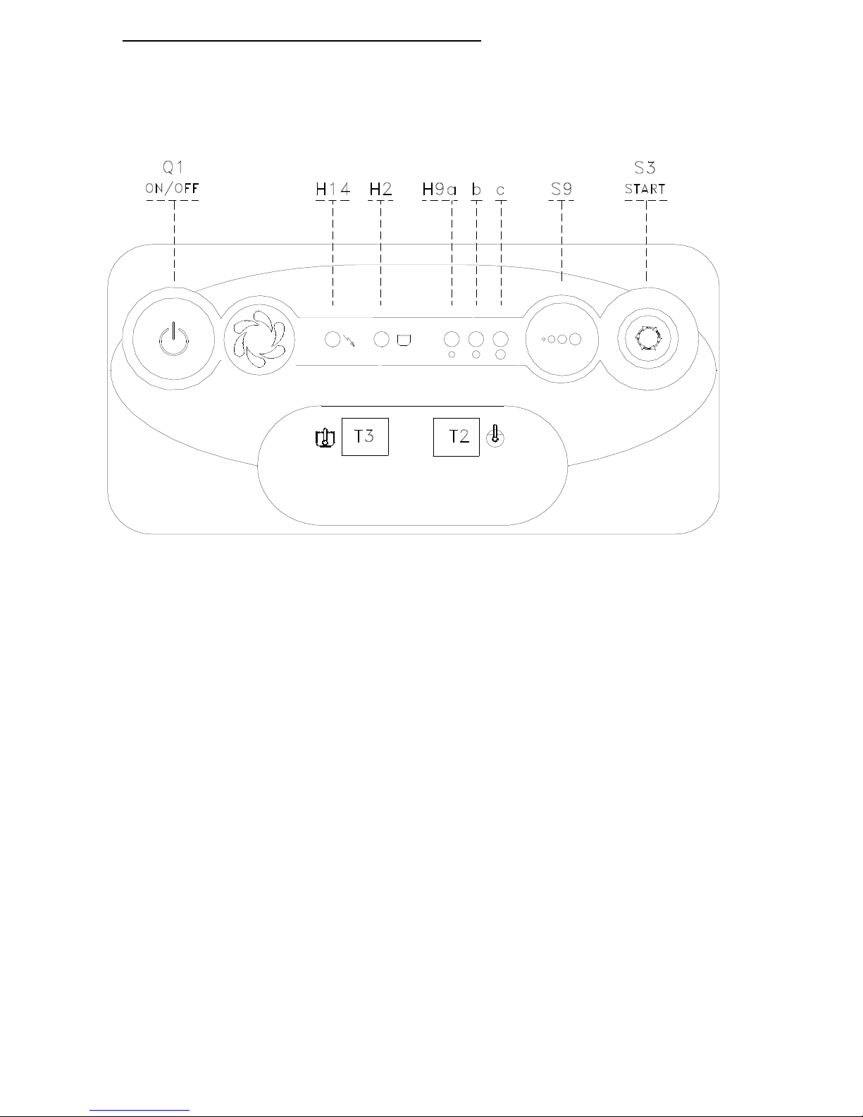
CONTROL PANEL
CONTROL PANELCONTROL PANEL
CONTROL PANEL
Q1
Main switch
H14
Pilot lamp " check "
H9a-b-c
Pilot lamp "cycle"
H2
Pilot lamp "machine ready"
S3
Push button "WASH or DRAIN CYCLE START"
S9
Cycle selector / AUTOMATIC or MANUAL startup
T2 B
oiler thermometer
T3
Tank thermometer
Page 5

INSTRUCTIONS FOR THE USER
5
OPERATION AND USE
1. Before washing make sure that:
• the wall-mounted on/off switch is switched on;
• the water tap is open;
• water is present in the distribution network;
• the pump protection filters are installed in their respective positions;
• the overflow in inserted;
• all rotating parts are free;
• the rinse aid dispenser is full;
• make sure that dishware is in good conditions as it may cause cleaning
difficulty and haven bacteria.
2. Press the "Q1 on/off" button ("H14" ON) to enable the automatic wash
tank filling and the consequent triggering of the heating element.
Wait that the temperatures are 55°C for washing "T3" and 80-85°C
for rinsing "T2" (the lamp"H2" ON).
3. Pour about 30 gr. of detergent directly into the tank, paying attention to
distribute it uniformly on the filters, the quantity being according to
supplier's instructions. Add 15 gr. every 4 cycles to achieve a concentration
of 1,5 gr./lt. In order to respect our environment, use only the correct amount
of detergent.
When using chlorinated detergent, it is suggested to use an automatic
dispenser; otherwise, brownish spots might appear on the surfaces due to
chlorine reactions. Detergent should always be placed near the pump filter.
4. Then, introduce the glasses or the cups to wash, after having removed the
solid waste and having placed them into the proper racks. The cups and the
glasses should be turned upside down, while the cutlery should be put
vertically into the proper container, and the same applies to dishware.
Page 6

INSTRUCTIONS FOR THE USER
6
5. Press the "S9" button to select the wash cycle according to conditions of
the dishware:
• (H9a ON ) ................short cycle ............ for glasses and cups
• (H9b ON).................medium cycle........ with normally dirty dishes
• (H9c ON) .................long cycle.............. with particularly dirty dishes or
. deep dishes
• (H9a-b-c ON)...........intensive wash...... max 8 min.
6. Close the door and press the "S3 start" button to start cycle.
The lamp flashes.
The activation of a cycle is shown by the flash of the lamp:
H9a for the short cycle
H9b for the medium cycle
H9c for the long cycle
H9a-b-c alternating for the intensive wash (max 8 min.).
It is possible to perform an intensive wash (lamp "H9a-b-c" OFF) that will
remain activated until the "S3 start" button is pressed again or a maximum
time of 8 min. is reached; the pause, rinse and drain (if required) phases will
follow.
To opening the door, the lamp "H14" flashes quickly.
To start up the the cycle AUTOMATICALLY (by opening and closing the
door), you will need to change the cycle start up mode. Press and hold the
"S9" button (approx. 10sec) until the pre-selected cycle lamp remains
blinking lite and the washing cycle will then start up AUTOMATICALLY
when the door is closed.
ATTENTION: Machine in conformity with the existing hygienic
standards, guaranteeing a final rinse at 85°C. Wash cycle automatically
lengthened if final rinse temperature is not reached.When this auto-cycle
intervenes and the cycle is pro-longed, after 8 minutes the "H14"
indicator flashes to indicate this intervention and the cycle continues
(water supply temperature is likely to be the problem, otherwise contact
an assistance center since it is a rinse water heating intervention.).
Page 7

INSTRUCTIONS FOR THE USER
7
7. Remove the rack and slightly incline it to permit a perfect drain; allow
dishware to dry and after having washed one’s hands, handle the rack in
order not to touch the dishware inside then place the rack on hygienically
clean shelves.
To change the tank water if necessary.
8. DRAIN CYCLE
At the end of washing, with the machine off, take out the overflow pipe
from the tank and wait until it is completely empty then close the door
and turn on the machine for a few minutes to wash the machine.
Then again press the switch "Q1 on/off" to turn off the machine and wait
until the tank is completely empty.
For machines with drain pump, open the front door, pull out the
overflow pipe, turn ON the machine, and press the "S3 start" button for
start the drain cycle. The lamp "H14" and "H9" flashes.
The machine will carry out the drain cycle for 2 min. and 20 sec.
At this point, the tank filter can be taken out, in order to be washed, then
replace it with the overflow in its place.
SELF CLEANING AND DRAIN CYCLE
For machines with drain pump, turn OFF the machine, pull out the
overflow pipe, close the front door and press the "S3 start" button for start
the cycle. The lamps “H9a-H9c” and "H14" flashes.
The machine will carry out the drain cycle for 2 min. and 20 sec.
At this point, the tank filter can be taken out, in order to be washed, then
replace it with the overflow in its place.
(For further use , first switch off the machine).
For any further information concerning equipment cleaning, read chapter
"USEFUL SUGGESTIONS".
DEACTIVATING THE DISHWASHER AT THE END OF THE DAY
9. At the end of service, turn off by using the main wall switch and close the
water and steam* valve.
(*) for steam machines only
Page 8

INSTRUCTIONS FOR THE USER
8
INSTRUCTIONS DURING THE WASHING
1)Do not plunge bare hands into the water containing the detergent. If this
happens, wash them immediately and abundantly with fresh water.
2)When the machine is operating, do not open the door too rapidly.
3)Use only specific anti-foaming detergents.
4)Disconnect the equipment in case the machine is out of order or it does
not work properly. For the repairs consult a technical assistance centre
authorised by the manufacturer and ask only for an original spare parts.
5)Never modify the thermostat settings.
6)Check that the wash temperature is 55-60°C.
7)Wash tank water should be changed at least twice a day or according to
daily wash requirements.
8)Do not subject clean dishware to any further cleansing treatment such as
brushes or drying towels.
If these instructions are not followed, the safety of the equipment can be
compromised.
ALARMS
ALARM A4
Tank temperature probe not connected.
Boiler temperature probe not connected.
ALARM A5
Tank temperature probe in short circuit or the
temperature exceeds 99°C.
Boiler temperature probe in short circuit or the
temperature exceeds 99°C.
Page 9

INSTRUCTIONS FOR THE USER
9
USEFUL SUGGESTIONS
1) MAINTENANCE
IMPORTANT: Before carrying out the cleaning and maintenance
operations, disconnect the equipment from the electric supply.
Frequently check and clean the nozzles. The frequency of this operation will
depend on the quantity of residues, which may result in an unsatisfactory
washing result.
♦ For the inside and outside cleaning of the machine, do not use corrosive
products such as sodium hypochlorite (bleach) savelling water and
hydrochloric acid, acids, steel wool or steel brushes.
♦ The presence of calcium and magnesium salt in the water can
compromise machine performance, thus ask qualified personnel to
remove the deposits periodically.
♦ In order to avoid some oxidation risks, or chemical reactions, generally
the stainless steel surfaces have to be well cleaned.
2) OPTIMAL RESULTS:
A possible wash deficiency can be noticed when residue remains.
Marks can be caused by an insufficient rinse: in this case check
that the rinse nozzles are clean and that there is sufficient water supply
pressure.
In case of dishware residue check that:
• the washing nozzles are clean
• the water temperature is around 60°C
• there is detergent
• the pump suction filter is clean
• the racks are suitable for the dishes and cutlery that are to be washed
• the position of the cutlery and the dishes in the racks are correct
3) TEMPORARY MACHINE NON-USE
In case the machine is stopped for some weeks, it is recommended before
closing it to fill the tank and run the machine with clean water, then empty it
out, in order to avoid the forming of bad odour and that any residue remains
in the pump.
If necessary repeat this operation until the water leaving the machine is
clean.
If the machine is stopped for many weeks, it is recommended to oil the
stainless steel surfaces with paraffin oil and to discharge the water from the
boiler and the electric pump.
Page 10

INSTRUCTIONS FOR THE USER
10
4)SANITIZING THE MACHINE
Sanitizing the machine at least once a week is of the utmost importance in
order to guarantee hygiene even when the machine is not in use.
It is advisable to use a disinfecting product suggested by an authorised
detergent dealer.
The use of this product will satisfy hygienic requirements, even during
machine non use.
Before switching off the machine run the machine briefly with clean
water.
5)HARD WATER CONDITIONS
If a hard water supply is present, mineral deposits will form within the
machine and also on dishware.
In order to avoid the above conditions a periodic removal of these deposits is
necessary.
The frequency and method of this operation upon consultation by your
detergent supplier.
Page 11

11
INSTALLATION AND MAINTENANCE
INSTRUCTIONS
The following instructions are addressed to a qualified personnel the only
one authorised to carry out checks and repairs, if any.
The manufacturer declines any responsibility in the case of interventions
made by a non qualified personnel or the use of spare parts other than those
supplied by the Manufacture.
Page 12

INSTRUCTIONS FOR TECHNICAL PERSONNEL
12
INSTALLATION
During installation, carry-out a good machine levelling, which is a
prerequisite for a correct operation thereof. In order to prevent any damages
caused by vapours going out of the machine, make sure that the surrounding
materials don't deteriorate in their presence.
1)ELECTRICAL CONNECTION
The electrical power supply shall be fed to the machine by connecting it to a
wall-mounted differential magneto-thermal on/off switch, with a contact
aperture distance equal to or greater than 3 mm.
The said magnetothermal on/off switch should be rated according to the
following table, as a function of the power supply voltage, the machine
model, and the heating type (electrical or steam heating).
Modèle Type de
chauffage
Branchement
électrique (V)
Puissance
totale (kW)
Absorption
électrique (A)
Section câble
alimentation
(mm²)
Interrupteur
a mur
(A)
GE605 RCD électrique
380-400V/3N
9 13,7 2,5 16.0
GE755 RCD électrique
380-400V/3N
9 13,7 2,5 16.0
GE805 RCD électrique
380-400V/3N
9 13,7 2,5 16.0
GE1005 RCD électrique
380-400V/3N
15 23,0 4 32.0
GE1255 RCD électrique
380-400V/3N
15 23,0 4 32.0
N.B.: Check that the voltage which the machine is set to correspond to the
power supply voltage available.
Power cable cross section must not be less then that indicated in the table. If
the cables are not protected by a sheathing, use a flexible, protected cable in
Polychloroprene with equivalent H07RN-F characteristics.
Check the line length; should it be too long, conform the line cross section to
such line length and to current drain; don't submit the power supply cable to
traction.
Cable must be connected to X1 terminal block passing through the cable
brake (see refer to electrical diagram).
Page 13

INSTRUCTIONS FOR TECHNICAL PERSONNEL
13
The electrical safety of this equipment is only assured if it is connected as
follows.
It is necessary to connect the equipment to an effective ground installation,
as specified by the electrical safety regulations in force.
Check that this basic requirement is complied with and, in case of doubt, ask
for a careful check of the installation by a qualified personal.
In addition, the equipment shall be part of an equipotential system, the
effectiveness of which should be checked according to the regulations in
force.
The connection should be made at the screw marked by the respective label
located on the equipment back side. ( )
The manufacturer declines any responsibility for any damages caused by lack
of an effective ground installation.
2)WATER CONNECTION
Install a water cock in a well accessible place, terminating in a 3/4" gas
fitting, which the draining pipe shall be connected to.
Carefully comply with any national or regional regulations in force.
The operating pressure should not be less than 2 bar nor greater than 4 bar
(200/400 kPa). In order to get a good result, it is suggested that the feeding
water has an hardness not greater than 5/10°F and a temperature of 55°C 0+10°C.
3)STEAM FEEDING (*)
As far as steam feeding is concerned, connect to the machine fittings
indicated in the installation drawings. In order to make the equipment
independent from the general steam distribution network, it is necessary to
use gate and 1”gas on/off valves.
This type of feeding should be supplied at a pressure ranging from 0.5bar
(110,8°C-50kPa) to 2bar (132,9°C-200 kPa).
The steam used should be absolutely saturated and dry.
4)WATER DRAIN
Install a water drain at the floor level, complete with siphon, and connect to
the drain through a flexible pipe, making sure that there are no throttlings
along it. Make sure that the draining pipe is resistant at a temperature of
70°C.
Page 14

INSTRUCTIONS FOR TECHNICAL PERSONNEL
14
5) STEAM EXHAUST (*)
The condensed steam exhaust shall have an appropriate slope toward the
recovery installation or a blow-by pump, in order to guarantee an
autonomous scavenging of the condensed steam.
_______________________
(*) for steam machines only
6) LOADING AND UNLOADING OF THE MACHINE
For the transportation of the machine from the delivery point to the final
installation position, use a fork lift or adequate lifting equipment used by
authorised staff. Lift the machine by its frame, taking care that any
protruding parts are not damaged (discharges, wiring etc.).
7) MACHINE DISMANTLING
At the end of its normal lifetime, the machine has to be taken apart according
to the local regulations in force by separating the components as follows:
• metal parts: hood, platforms, frames, filters
• electrical parts: motors, remote control switches, microswitches, wiring
• plastic parts: racks, connections
• rubber parts: tubes, sleeves
Page 15

INSTRUCTIONS FOR TECHNICAL PERSONNEL
15
WIRING DIAGRAM
B2
Boiler temperature probe
B3 Tank temperature probe
C1 Anti noise filter
E2 Booster heater
E3 Tank heater
K1 Relais
K2 Tank filling relay
KS1 Door switch relay
KE2 Booster heater contactor
KE2b Safety contactor of booster heater
KE3 Tank heater contactor
KM2 Rinse pump contactor
KM3 Wash pump contactor
KM3a Wash pump contactor
M2 Rinse pump
M2a Rinse pump
M3 Wash pump
M3a Wash pump
M5 Drain pump (if required)
MD Detergent dispenser (if required)
S1 Door switch
S2 Tank pressure switch
S11a RCD pressure switch
SE2 Booster thermostat
SE2a Booster thermostat
SE2b Booster safety thermostat
SE3 Tank thermostat
Y11 RCD filleng solenoid valve
Y2 Tank filling solenoid valve
X1 Junction
The manufacturer declines any resonsibility for any printing errors contained
in this booklet. The manufacturer also reserves the right to make any
modifications to its products that do not affect the basic characteristics
thereof.
Page 16

GE…-eng
12-2010
 Loading...