

Page 1
I
INSTRUCTION MANUAL
Heat Monitoring and Control Instrument for Transformers
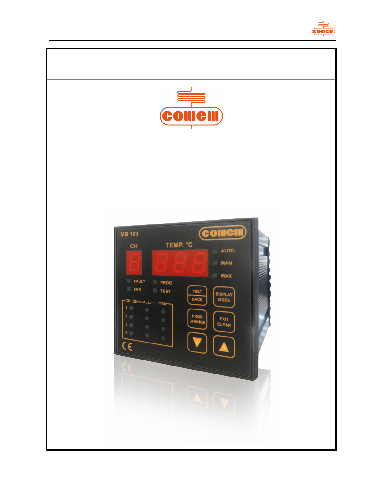
“MB 103”
Temperature Control Unit
54105T – MB 103 –
REV0
2
Page 2

II
Page 3

0
CONTENT:
1 SAFETY
1.1 Safety instructions 1
1.2 Specified applications 1
1.3 Safety notes on equipment operation 2
2 TEMPERATURE CONTROL UNIT TYPE “MB 103”
2.1 Drawing 3
2.2 Hardware characteristics 4
2.2.1 Front panel 4
2.2.2 Rear panel 5
2.3 Main characteristics 6
2.4 Operation 6
2.5 Temperature display 6
2.6 Programming 6
2.6.1 S4 profile 8
2.7 Correct operation checks 9
2.8 Signal tests 9
2.9 Zeroing procedure 9
2.9.1 Factory settings 10
3 INSTALLATION 10
4 CONNECTION
4.1 Power supply 10
4.2 Inputs 10
4.3 Relay tests 10
5 OPERATION AND MAINTENANCE
5.1 Starting 11
5.2 Maintenance 11
5.3 Fault monitoring 12
5.4 Movement, transport and storage 12
6 SOFTWARE
6.1 Introduction 13
6.2 Installation 13
6.3 Use 14
6.3.1 Parameters 15
6.3.2 Status 16
6.3.3 Temperatures diagram 17
Page 4
1
1. SAFETY
1.1 Safety instru ctions
Make sure that the personnel who ins tall, put into service and operate the
“MB 103 Temperature Control Unit”:
· Are technically qualified and competent;
· Fully comply with these assembly instructions.
Improp er op er ation or mis use could endanger :
· Life and limb
· The equipment and other propert y of the operator
The safety instructions in this manual are shown in three different forms t o emphas ize the importance of the operation.
1.2 Specified applicat ions
The “MB 103” Temperature Control Unit is used in r esin or dr y type tr ansform ers and can als o b e easily adapted for use in oil
transformers.
The “MB 103” Temperature Control Unit uses PT100 temp erature probes for constant monitoring of transformer temperature in four
points: f or example, three on th e t ransfor mer windin g columns and one on the machi ne's magn etic circuit.
If the transformer fails to function correctly and its temperature ris es, the Temperature Control U nit generates an electric alarm signal.
If the temp er atur e r eac h es dan g er l evel , th e u nit gen er at es a s ec ond int er vent i on l ev el. T his can be conn ec t ed t o a mac hin e s t op swi tc h
that functions in dependently of the alarms .
A cooling system control program is also i mplemented in the unit.
WARNING
This information indic ates partic ular dan ger to lif e an d health.
Disregarding such a warning can lead to serious or fatal inj ury.
CAUTION
This information indic ates particular d anger to equipment and/or other property of t he user.
Serious or fatal injury cannot be excluded.
NOTE
These notes give important or specific information concerning the equipment or how to work with the
equipment.
Page 5
2
1.3 Safety notes on equipment operation
The electrical installat ion must conform to the national safety regulations.
The MB 103 Temperature Control Un it has double insulation. Earthing is not requ ired.
CAUTION
The wires must be f ixed properly.
CAUTION
The MB 103 Temperature Control Unit must not b e installed near sources of electromagnetic interfer ence.
MB 103 conforms to the following standards:
· EN 50081-2: Electromagnetic compatibility - Generic emission standard
Part 2: Indus tr ial envir on m ent .
· EN 50204: Radiat ed electrom agnetic field f rom digital radio teleph ones - I mmunity test
· EN 55011: Industrial, scientific and medic al equip ment - Radio-f requency distur bance
characteristics - Limits and methods of measurement.
· EN 61000-3-2: Electromagn etic comp atibility (EMC) - Part 3-2: l imits - Limits for harmonic
current emissi ons (equipment inpu t current up to and including 16 A p er p hase).
· EN 61000-6-2: Electromagnetic compatibil ity (E MC) - Part 6-2: G eneric standards -
Immunity of industrial environments.
· EN 61000-4- 2: Electrom agnetic c ompatibilit y (EMC) - Part 2-4: E nvironment -
Compatibility levels in industrial plants for low-frequency conducted disturbances
· EN 61000-4-4: Electromagnetic compatibil ity (E MC) - Part 4-4: T esting and meas urement
techniques - Fast transient immunity test.
· EN 61000-4-5: Electr omagnetic compatibilit y (EMC) - Part 4-5: T esting and meas urement
techniques - Surge immunity test.
· EN 61000-4-6: Electromagnetic compatibility (EMC). Part 4: Testing and measurement
techniqu es. Section 6: Immunit y to conduct ed disturbanc es, induc ed by radio-f requenc y
fields.
WARNING
All relevant fire protection regulations must be strictly observed.
Page 6
3
2. “MB 103” TEMPERATURE CONTROL UNIT TYPE
2.1 Drawing
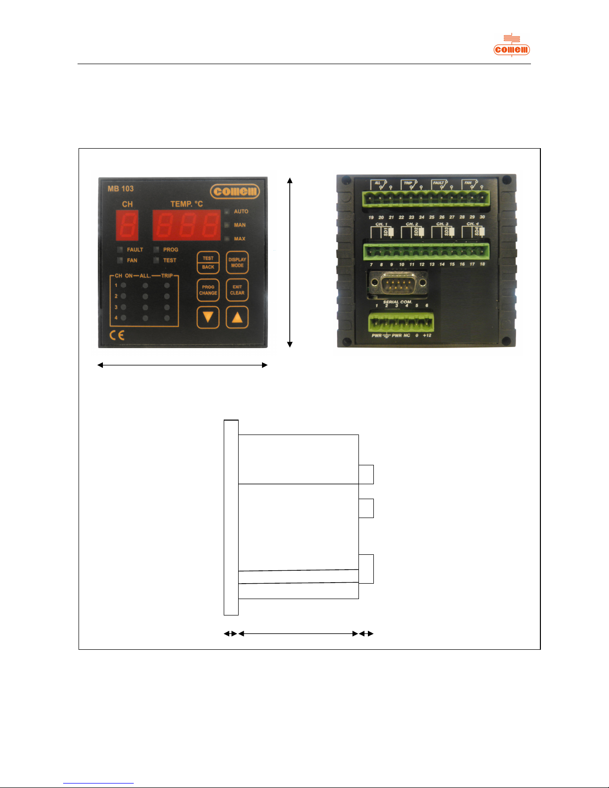
External dimensions (Fig. 1) of the “MB 103” Temperature Control Unit:
FRONT PANEL REAR PANE L
SIDE VIEW
Fig. 1
96 mm
96 m m
107 mm9 mm 10 mm
Page 7
4
2.2 Hardware characteristics
· Container: self-extinguishing ABS
Dimensions: box 170 m m x 110 mm x 105 mm (DIN 43700)
· Front panel: self-extinguishing Exon
Dimensi ons: 96 mm x 96 mm
· Weight: 0.5 kg
· Display:
Temper ature: 3 numbers, each wi th 7 segments
Channel: 7 segments
· LEDs 19 signals
· T erminal board: withdrawab le an d p olarized, in acc ordance with IE C 99 8-1 and IEC 998-2-1
· Climatic category 40/11021 according to IEC
· Power supply: univers al, range 24-220 V ± 10% in DC or AC at 50 Hz ± 2% f requ ency or 12V in DC
· Operating temperature: -20°C +60°C
· Inp uts: 4 PT 100 (or PTC) r esistance thermometers, range f rom -10°C to 20 0°C
· Outputs : 4 r elays with 5 A contacts, 250 V A.C.
· Memor y: EEPRO M with data ret ention f or more than 10 years
· Precision: ± 1% of full-scale value + 1 digit
· Insul ation: Double galvanic insulati on between power suppl y, micropr ocessor and temperatur e pr obes (2500 V t est voltage)
· Humidity: 90% without condensation
· Consumption: 4 VA
· Construction in accordance with regulations
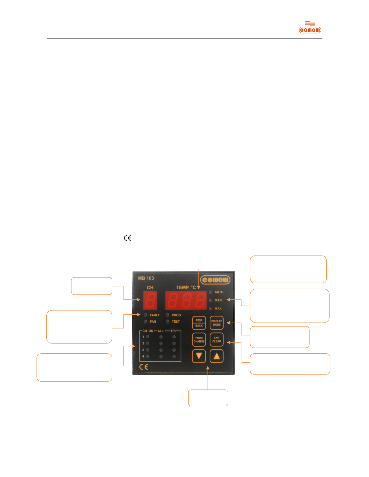
2.2.1 Front pan el
Fig. 2
Number of
probe
LEDs
- fault
- programming
- fan
-
test proc ed ure
LEDs
- probe operati on
- alarm threshold exceeded
- release threshold exceeded
- Probe temperature
- Probe state:
SSP (probe in short-circuit)
OPP (probe interrupted)
LEDs:
- automatic m od e
(CH with higher temperature)
- manual mode
- maximum temperature reached
- Increase
-
Decrease
- LED Test
- Type of display
(AUTO, MAN, MAX)
- Programming
- Quit test
Reset
Page 8
5
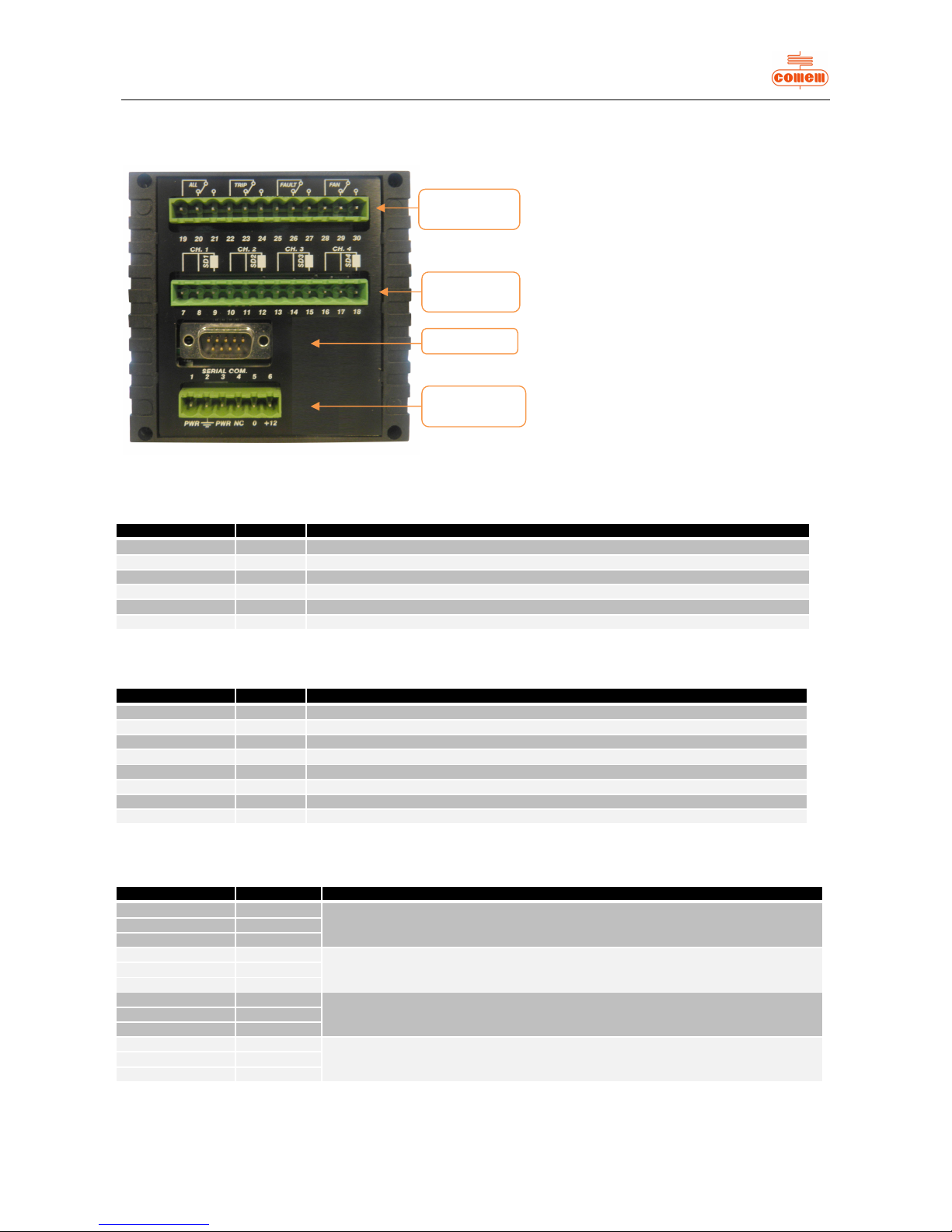
2.2.2 Rear panel
Fig. 3
Power supply
Terminal number Input Description of operation
1 PWR From 24 to 220V AC to DC universal power suppl y wi th + /- 10% vari ations allowed
2 Earth Must be connect ed using c able at least 1.5 mm in section
3 PWR From 24 to 220V AC to DC universal pow er suppl y wi th + /- 10% vari ations allowed
4 Terminal not connected
5 0 Input for 12V DC power supply
6 +12 Input for 12V DC power supply
Probe inputs (PT100)
Terminal number Input Description of operation
7 - 8 SD1PF Probe 1 c old pole input
9 SD1PC Probe 1 hot pole input
10 - 11 SD2PF Probe 2 cold pole input
12 SD2PC Probe 2 hot pole input
13 - 14 SD3PF Probe 3 cold pole input
15 SD3PC Probe 3 hot pole input
16 - 17 SD4PF Probe 4 cold pole input
18 SD4PC Probe 4 hot pole input
Auxiliary circuits
Terminal number Input Description of operation
19 ALL1 - C
Terminals of ALARM circuit
20 ALL1 - NC
21 ALL1 - NA
22 ALL2 - C
Terminals of RELEASE circuit
23 ALL2 - NC
24 ALL2 - NA
25 FAULT - C
Terminals of FAULT circuit
26 FAULT - NC
27 FAULT - NA
28 FAN - C
Terminals of VENTILATION circuit
29 FAN - NC
30 FAN - NA
RS-232 port
Auxiliary
circuits
Probe
connection
Supply
connection
Page 9

6
2.3 Main characteri stics
System programm ed directly from the front panel.
Each channel can be selected independently.
Automatic display of max. temperature and relative channels.
Softwar e configur ation f or controlling inputs and outp uts.
Maximum temperature memorized for each channel.
Relay t est command.
Programmable ventilation settings.
Up to f our channels during activation.
Two thresholds: one alarm thres hold and one release thr eshold with change-over contacts .
Automatic probe fault indicator with change- over contact.
2.4 Operation
The software imm ediately detects, saves and signals any temperature irregularities i n the automatic mode.
The entire program ming pr ocedure controls b oth the req uests and data entered in the smart mode.
The Temp erature C ontrol Unit settings are standard factory values that can be modif ied as required. Th e alarm thr eshold is 140°C with
releas e at 1 60 °C and ventilation excluded.
The 19 LEDs on the display allow the MB 103 unit to clearly signal an d handle information concerning the temperature situation.
2.5 Temperature display
The Temperatur e Control U nit always switc hes on in the autom atic mode.
To change the dis play, press
: when the key is pressed, the operating mode of the instrument c hanges in sequenc e:
“AUTO”, “MAN” and “MAX”
AUTO: Automatic operation
Both the maximu m temperature and the channel this measurement comes from are
displayed in th e automatic oper ation mode.
MAN: Man ual operation
The temperature of each sensor is displayed in real time in the manual operation m ode. Th e arrow k eys are used to
scroll the active channels.
MAX: Maxi mu m op eration
The maxi mum temp erature reach ed by each probe is displayed in the maximum operati on mode. The arrow keys ar e used to
scroll the active channels.
2.6 Programming
Press the key for 3 seconds to program.
The “PROG” LED will lig ht up on the instrument panel and the letter “S” followed by a number will appear on the display.
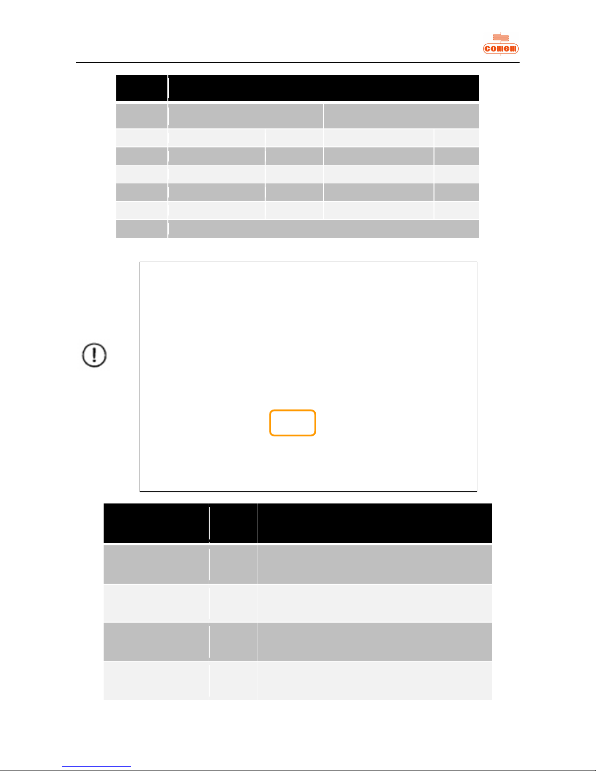
Use the arrow keys to re-program the operating mode of the unit as shown in the table bel ow.
The table contai ns four pre-defi ned profiles f or program ming the active channels and a fif th profil e.
DISPLAY
MODE
PROG
CHANGE
Page 10
7
Profile
Setting
Active channels
Channels with active ventilation
CH1, CH2 and CH3 CH 4 CH1, CH2 and CH3 CH4
S 0 YES NO NO S 1 YES YES YES YES
S 2 YES YES NO NO
S 3 YES NO YES S 4 Each channel can be activated as well as the relativ e ventilation
Display request
sequence
Profile Description
A nnn 0,1,2,3
Setting of the alarm threshold common to the
channels activ ated by profile selection (see previous
table)
t nnn 0,1,2,3
Setting of the trip threshold common to the channels
activated by profil e selection (see previous table)
L nnn 1,3
Setting of the ventilation stop threshold common to
the channels activated by profile selecti on (see
previous table)
H nnn 1,3
Setting of the ventilation start threshold common to
the channels activated by profile selecti on (see
previous table)
NOTE
For profiles 0, 1, 2 and 3, the settings inc lude one single alarm
threshold and one single release threshold common to all activated
channels.
The ventilation setting (profiles 1 and 3) will also have common
thresholds.
Profile 4 is useful when maximum flexibility is required since any
combination of active channels can be selected, while activation of
the alarm and release thresholds and ventilation can be set for these
channels independently.
Once the required operating profile has be en selected, it must be
confirmed by pressing the key.
Programm ing proceeds with a request for entry of the alarm and
release thresholds and, for the profiles concerned, entry of the
ventilation activation and dea ctivation thresholds as shown in the
table.
PROG
CHANGE
Page 11
8
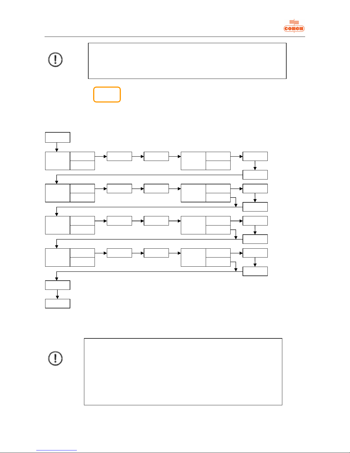
Use profile S 4 for maximum freedom when making the set tings.
Select S 4 and press the key for each confirmation.
if this option has b een selected, programming will follow the Fl ow -Chart b elow (consult the previous note when changing and c onfirming
the “n” and “nnn” val ues):
2.6.1 S4 profile
n CH1
n = 1
n = 0
S 4
A nnn
t nnn
n FAN
n = 1
n = 0
L nnn
H nnn
n CH2
n = 1
n = 0
A nnn
t nnn
n FAN
n = 1
n = 0
L nnn
H nnn
n CH3
n = 1
n = 0
A nnn
t nnn
n FAN
n = 1
n = 0
L nnn
H nnn
n CH4
n = 1
n = 0
A nnn
t nnn
n FAN
n = 1
n = 0
L nnn
H nnn
F Ftm
F nn
NOTE
Entry of a value other than zero for the F FtM parameter, under the F nn item,
specifies a time interval in hours after which ventilation will function for 5
minutes, regardless of the temperature present.
This function is available even when ventilation has not been applied to any of
the active channels.
Each channel can have different values for each threshold and ventilation
control can occur with any combination of channels.
PROG
CHANGE
NOTE
Confirmati on of “nnn” can be displayed at any moment by pressing the key.
Use the arrow keys to make changes.
Page 12
9
2.7 Correct operati on checks
The unit features two test levels to ensure th at the switchboard is reliable and the state signaled correctly.
The first level is dedicated to the front panel signaling LEDs,
while the other checks to make sure that the command relay functions properly.
2.8 Signal tests
Press the on the control panel to find out whether there are any faulty components.
All 19 LEDs and the dis play segments will light up for 2 seconds .
2.9 Zeroing procedure
Resetting the re-entered fault signal.
If a probe is faulty, the Temperature Control Unit indicates:
• release relay “Fault”
• the “alarm”, “trip” and “fault” LEDs com e on
• the fault channel is displayed
• an error mess age is displayed alongside the f ault ch annel:
SSP: probe short-circuited
OPP: pr obe interrupted
If the fault is intermittent (as in the case of faulty cables), the faulty sensor can be safely identified when the release signal returns since
the LED continues to flash.
To reset the fault signal , press for two seconds until the FLt signal appears on the display.
The fault signal reset func tion can be used in both the automatic and manual modes.
How to reset the maximum temperatures detected:
The function allowing the detected maxi mum tem peratures to be reset is only available in the maximum log displ ay mode ( “MAX”).
This function allows the maximum logs to be reset to the current temperature values.
To reset, press for two seconds until the rES signal appears on t he displ ay.
2.9.1 Facto ry setting s
TEST
BACK
EXIT
CLEAR
CAU
TION
To restore the factory settings, access the programming mode and press
the key for a few seconds.
Do not confirm the last step if you wish to quit the programming mode without
saving the changes made to the thresholds.
Quitting will occur automatically after about 1 minute.
EXIT
CLEAR
PROG
CHANGE
Page 13
10
Parameters to enter
Message
displayed
Set value
Instrument state S n 0
(channels 1, 2, 3 active with ventilation
excluded)
Alarm temperat ure A nnn 140
Release temperature t nnn 160
Ventilation Start value H nnn 100
Ventilation Stop value L nnn 90
3. INSTALLATION
The MB 103 Temperature C ontrol Un it must be installed inside the switchboard compartment and then fixed in place with th e fastening
components and screws provided.
Connect the power s upply (u niversal power s upply 24V – 220V AC/DC or 12V DC).
Connect the pr obes to the relative connection.
Connect th e auxiliary circuits (alarm, trip, fault, fan) to the electric al connections.
4. CONNECTION
4.1 Power supply
4.2 Inputs
4.3 Relay tests
The oper ation test for all the relays can be performed vi a the men u.
Press the for about 2 seconds until th e “TEST” LED comes on.
Press ag ain to test the other relays .
Press to quit the relay tes t menu (see table below).
WARNING
The instrument reads up to PT 100 probes.
Dust, humidity and corrosive gases should be avoided. Keep away from heat
sources. The maximum operating temperature of the instrument is 60 °C.
WARNING
The power supply is universal: 24V - 220V AC/DC or 12V DC
WARNING
Up to four
PT100
resistance thermometers
TEST
BACK
PROG
CHANGE
Page 14
11
Display
State
Description
n ALL
n = 0 Deactivated
Alarm relay test
n = 1 Activated
n trP
n = 0 Deactivated
Trip relay test
n = 1 Activated
n FLt
n = 0 Deactivated Fault relay test
(Inversion of the logic that allows faults to be signaled if t he supply
is locked can be consi dered)
n = 1 Activated
n Fan
n = 0 Deactivated
Ventilation relay test
n = 1 Activated
5. OPERATION AND MAINTENANCE
5.1 Starting
Power the terminals to start the MB 103 Temperature Control Unit.
5.2 Maintenance
Always p erform the foll owing inspections on the dehydrator during schedul ed maintenance of the transformer:
· Check the operation of the LEDs.
· Check the operation of the display.
· Check the failure contact.
CAUTION
If possible, group all parts of the instrument in a separate area from the relay
powering section.
Do not install the following components in the same switchboard: high power
teleswitches, count ers, relays, thyri stors and, especially, phase displacement
units, motors, etc.).
Before applying the MB 103 Temperature Control Unit, wait for the equipment
to reach room temperature (at least 1 hour).
Page 15
12
5.3 Fault monitoring
Fault
Cause
Solution
The instrument fails to
switch on
Faulty power supply Check connecti on
Power supply protected Remove protection and restore voltage
Fault alarm activated
Sensors faulty or wrongly
connected
Check and/or inv ert connections
between faulty and operat ing probes
Temperature indicated
by instrument is wrong
for one or more probes
Faulty probes
Check Ohm value of probe with
connections disconnected
Probes are connected
correctly but "Fault" LED
comes on
Fault is intermittent
See: Resetting the re-entered fault
signal (secti on 2.9)
The instrument i s
affected by disturbance
Probes are not shielded or
shield is not connected
Connect probes to shield and earth, but
only on instrument side.
If the fault is not mentioned above, please contact:
Comem
S.R. 11 Signolo, 22
36054 Montebello Vicentino (VI) - Italy
Tel +039 0444 449311 E-mail: [email protected]
5.4 Movement, transport and storage
All MB 103 Temperature Control Units are shipped inside a car dboard box on a
pallet to facilitate transport and storage.
As soon as the MB 103 Temperature Control Unit is received, the customer
must perform the following operations:
- examine the outer surface of the packaging to make sure it is intact;
- check that there are no breakages.
If damage is discovered, please contact Comem and provide the data in the
shipping list together with the serial num ber of the instrument.
Comem
S.R. 11 Signolo, 22
36054 Montebello Vicentino (VI) - Italy
Tel +039 0444 449311 E-mail: [email protected]
The MB 103 Temperature Control Unit must be stored in a dry place at
temperatures from -20°C to 40°C.
Page 16
13
6. SOFTWARE
6.1 Int roduct ion
The software allows the param eters and temperatures detected by the MB 103 in r eal time t o be displayed.
Create a Log File wher e all the d ata can be stored.
6.2 Installation
To instal l th e program us ed by th e MB 1 03 Tem perat ure C ontrol Unit, ins ert th e CD int o the PC dri ve and wait un til f or th e inst allati on
procedu r e autorun.
After a few minutes, if the autorun fails to appear, run the “Setup” program by means of “Computer resources” or “Explore resources”.
Fig. 1
Fig. 2
Fig. 3 Fig. 4
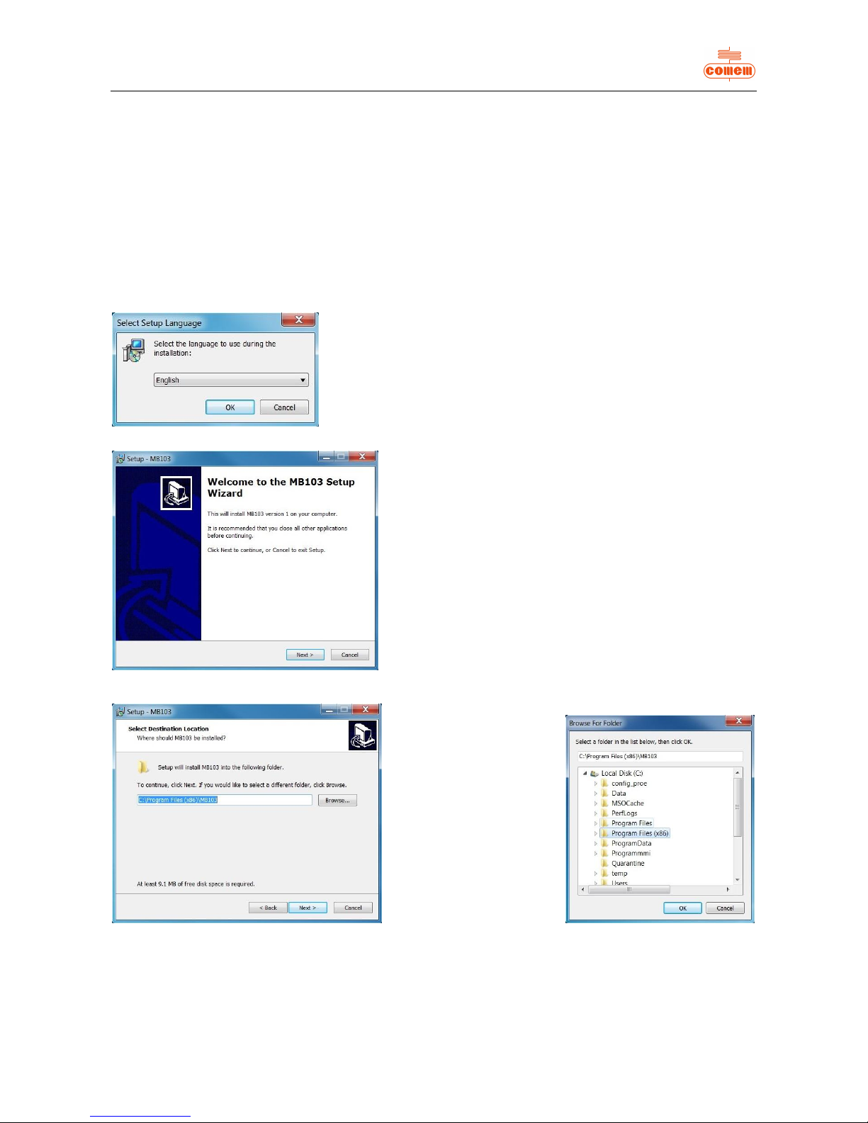
Select the instal lation l anguage
then press OK. (fig. 1)
Click on “Next”. (fig. 2)
Press “Browse”; (
fig. 3
)
Select the destination location of
the installation
and press “OK”; ( fig. 4)
Click on “Next”. (fig. 3)
Page 17
14
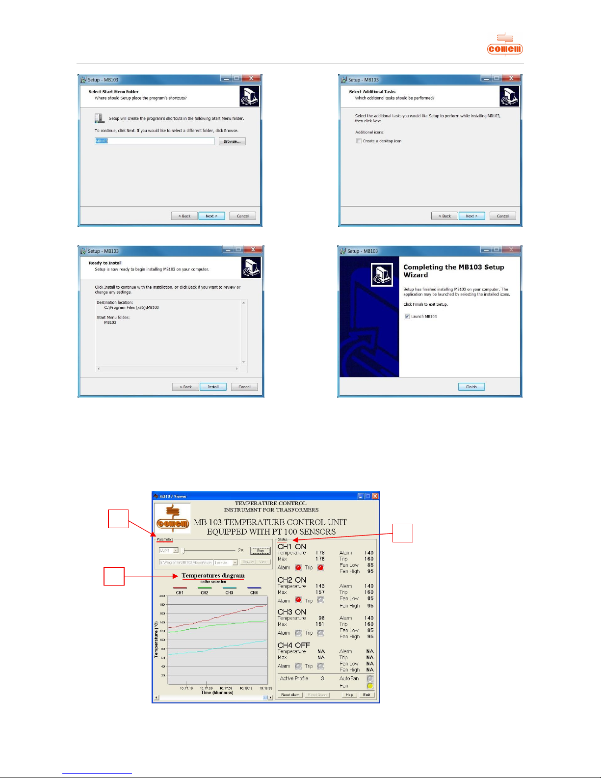
Fig. 5 Fig. 6
Fig. 7 Fig. 8
The installation procedure h as now t erminated.
6.3 Use
Once the program has been installed, click on the start Menu: “Start – Programs – MB 103” to run t he software.
the following page will ap pear:
Fig. 9
1
3
2
Click on “Next”.
(fig. 5) and ( fig. 6)
Click on “Install”.
(fig. 7)
then on “Finis h ”.
(fig. 8)
The initial window (
fig. 9
) is divided into
3 parts:
1. Parameters
2. Status
3. Temperatures diagram
Page 18
15
6.3.1 Par am eters
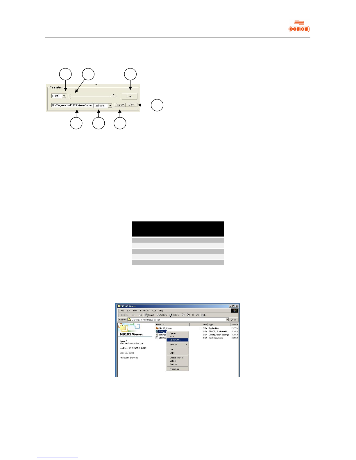
In the Parameters area (fig. 10) you can:
Fig. 10
1) choose which RS 232 t o enable: COM1 or COM2;
2) establis h the graph sampling time (mini mum 2s and maximu m 600s);
3) start acquiring data with “St art” or st op data acquisit ion with “Stop” ;
4) display the Log File with the “View” button;
5) create the Log File wit h t h e “Browse” button;
6) select the Log File sampling time interval from the pull-down menu;
7) view th e storage path of t he Log File.
The data acquired during the scanning process are stored in the Log File.
The file has a “.csv” type of extension so that it can be consult ed usin g the most widely used spreadsheets (Microsoft Excel, Calc).
In view of t he limit ed numb er of lines (about 65, 500), the progr am eliminates the oldest d ata and maintains the most recent ones.
For this reason, t he software has been designed to regulate the sampli ng time interval so as to maintain the most significant data for the
user in its memory (ta b. 1).
Sampling time
interval
Historical
data
1 minute 45 days
2 minutes 3 months
6 minutes 9 months
9 minutes 13 months
10 minutes 15 months
Tab. 1
Once data acquisition h as been stopped by pressing the “Stop” button, t he Log File can be consult ed by press ing “View ”.
If the required spreadsheet is not displayed, the program must be defined by using “Open with” in “Explore resources” or “Computer
resourc es” and clic king on Log F ile with the rig ht key of the mouse (fig. 11).
Fig. 11
123
4
567
Page 19
16
To display the Log File correctly, open the required file from “Explore resources” or “Comput er res ources” and then save with the
normall y used spreadsheet extension, us ing “S ave as”.
For example, Microsoft Excel uses extension “.xls” (fig. 12).
Fig. 12
6.3.2 Stat us
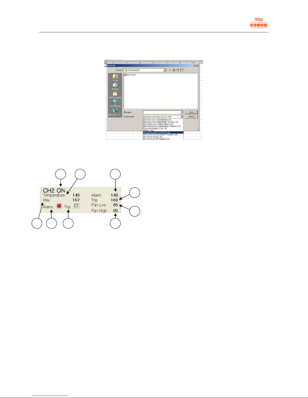
Sta tus (fig. 13) allows you t o view the s ettings of th e MB 103:
Fig. 13
· O N will appear if the t emperatur e detection channel 1) is activated , otherwise OFF will appear.
· The followi ng informati on is dis played f or each active c hannel:
2) the instantaneous temperature value;
3) the m aximum temperature value memori zed b y th e unit;
4) the alarm state: GREY is not active, RED if active;
5) the trip s tate: GREY is not active, RED if active;
6) th e trip tem perature of th e alarm;
7) the trip temper ature of the r elease;
8) the ventilation deactivation temperature;
9) the ventilation activation temperature;
· The letters NA will appear on a level with the Temperature 2), Max 3), Alarm 6),Trip 7), F an L ow 8), Fan High 9) values if not all
channels ar e ac ti ve.
134526789
Page 20
17
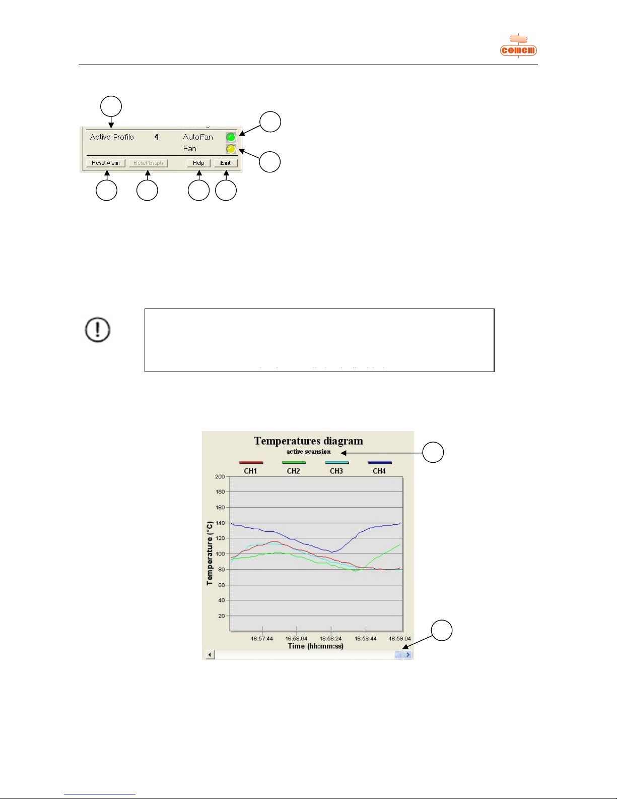
The follow ing information appears in the lower par t of the Status area (f ig. 14):
Fig. 14
1) the active profile;
2) the “Reset Alarm” key: deletes the ac tive alarms if pressed;
3) the “Reset Graph” key: deletes the data shown in th e graph (Fig. 15)
4) the visual AutoFan indication: GREEN if on, GREY if off;
5) the visual F indication: YELLOW if on, GREY if off;
6) the “H elp” k ey to access help online;
7) the “E xit” key to qui t the program.
6.3.3 Temperature diagram
The temperature trend detected over time can be vi ewed in the Temperatures diag ram (fig.15):
Fig. 15
Use the Scroll bar (1) to move the x-coordin ates so as t o display the instants pri or to the displayed times.
Press “m” on the keyboard to zoom t he graph area. Press “Esc” to go back to the main pag e.
The words “active scanning”(2) will appear if acquisition is acti v ated, otherwis e t he message will be “no active scanning”.
1
4
5
763
2
NOTE
If the Active Profile is number 4 and ventilation is activated (with Fan YELLOW
in colour),
then AutoFan will be GREEN.
1
2
Page 21
18
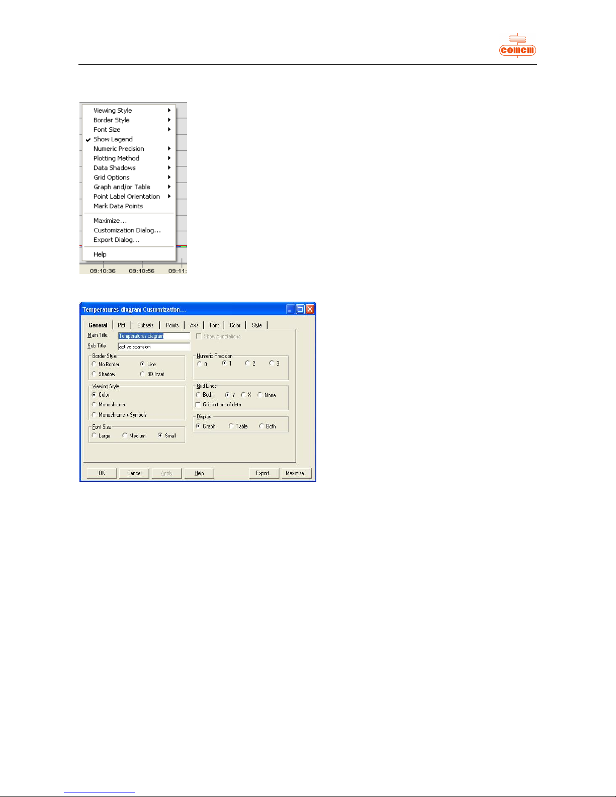
Click with the right key of the mouse when on the grap h area to display t he dial og window and change the parameters (fig. 16).
Fig. 16
Fig. 17
The main functions are as follows:
· Viewing Style: to change the colours of the graph
area;
· Show Legend: enabled if graph l egend is ticked;
· Plotting Method: allow s you to choose the mode
with which the temperatures on the graph are
displayed (histograms, lines, dots, etc...);
· Maximize: zooms th e graph area;
· Customization Dialog: allows you to access a
dialog m ask (fig. 17),
where you can:
Ø enable or disable the chan nels display ed
in the graph area (Subsets)
Ø change the number of points shown in
the graph area (Points)
Ø change the sc ale of the y-coordi nates
(linear or logarithmic) and the
temperature range ( Axis)
Ø change the colours and types of lines
and points (Style)
Page 22

19
 Loading...