

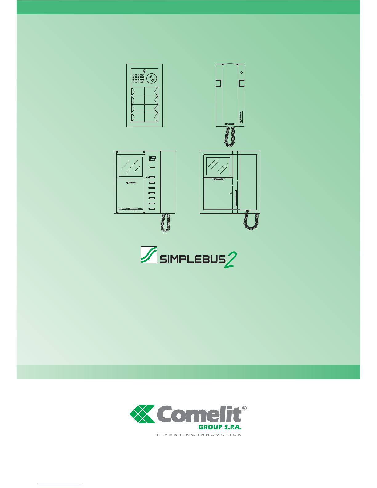
Comelit SIMPLEBUS 2 Installation Manual
1
Comelit Group S.p.A. - Via Don Arrigoni 5 - 24020 Rovetta S. Lorenzo BG Italy - tel. (+39) 0346 750 011 - fax (+39) 0346 71436
www.comelit.eu www.simplehome.eu info@comelit.it commerciale.italia@comelit.it export.department@comelit.it
Assistenza tecnica Italia 0346/750090
Commerciale Italia 0346/750091
Technical service abroad (+39) 0346750092
Export department (+39) 0346750093
TECHNICAL
SHEET
FOGLIO
TECNICO
FEUILLE
TECHNIQUE
TECHNISCHES
DATENBLATT
TECHNISCHE
HANDLEIDING
HOJA
TÉCNICA
TECHNICKÝ
LIST
ENIT FR DENL ES CZ
Guida di installazione
Installation guide
Guide d'installation
Installatie handleiding
Installationsanleitung
Guía de instalación
Pokyny k instalaci
FT SB2 24
GROUP S.P.A.
2
FT SB2 24
AVVERTENZE
• Effettuare l’installazione seguendo scrupolosamente le istruzioni fornite dal costruttore ed in conformità alle norme
vigenti.
• Tutti gli apparecchi devono essere destinati esclusivamente all’uso per cui sono stati concepiti. Comelit Group
S.p.A. declina ogni responsabilità per un utilizzo improprio degli apparecchi, per modifiche effettuate da altri a
qualunque titolo e scopo, per l’uso di accessori e materiali non originali.
• Tutti i prodotti sono conformi alle prescrizioni delle direttive 2006/95/CE (che sostituisce la direttiva 73/23/CEE e
successivi emendamenti) e ciò è attestato dalla presenza della marcatura CE sugli stessi.
• Evitare di porre i fili di montante in prossimità di cavi di alimentazione (230/400V).
WARNING
• Install the equipment by carefully following the instructions given by the manufacturer and in compliance with the
legislation in force.
• All the equipment must only be used for the purpose it was built for. Comelit Group S.p.A. declines any
responsibility for improper use of the apparatus, for modifications made by others under any title or scope, and for
the use of accessories and materials which are not the original ones.
• All the products comply with the requirements of the 2006/95/CE directives (which replace the 73/23/CEE directives
and the successive amendments). This is proved by the CE mark on the products.
• Do not run the riser wires in proximity of the power supply cables (230/400V).
AVERTISSEMENT
• Effectuer l’installation en suivant scrupuleusement les instructions fournies par le constructeur et conformément aux
normes en vigueur.
• Tous les appareils doivent être strictement destinés à l’emploi pour lequel ils ont été conçus. Comelit Group S.p.A.
décline toute responsabilité en cas de mauvais usage des appareils, pour des modifications effectuées par d’autres
personnes pour n’importe quelle raison et pour l’ utilisation d’accessoires non fournis par nous.
• Tous les produits sont conformes aux exigences des directives 2006/95/CE (qui remplacent les directives
73/23/CEE et amendements successifs). Cette conformité est signalée par le symbole CE figurant sur les produits.
• Eviter de placer les fils de montant à proximité des câbles d’alimentation (230/400 V).
WAARSCHUWINGEN
• Volg de instructies van de fabrikant nauwkeurig en installeer de materialen volgens de plaatselijk geldende normen
en wetgeving.
• Alle componenten mogen alleen gebruikt worden voor de doeleinden waarvoor ze zijn ontworpen. Comelit Group
S.p.A. is niet verantwoordelijk bij een onjuist gebruik van de apparatuur, of modificaties welke aangebracht zijn
zonder voorafgaande toestemming, evenals het gebruik van accessoires welke niet door de fabrikant zijn
aangeleverd.
• Alle producten voldoen aan de eisen van de richtlijn 2006/95/CE (die in de plaats is gekomen van de richtlijn
73/23/CEE en daaropvolgende wijzigingen). Dit wordt aangetoond door het CE-merk op de producten.
• Monteer de aders (bekabeling) niet in de nabijheid van voedingskabels (230/400V).
IT
EN
FR
NL

FT SB2 24
FT SB2 24
3
ACHTUNG
• Die Installationen sind nach den Anweisungen des Herstellers und gemäß den geltenden Vorschriften
gewissenhaft auszuführen.
• Alle Geräte dürfen ausschließlich nur zu dem Zweck eingesetzt werden, für den sie entwickelt worden sind. Comelit
Group S.p.A. lehnt die Haftung für unsachgemässe Verwendung der Produkte oder für unautorisierte Veränderung
von Produkten, sowie für alle Produkte, welche nicht von der Firma geliefert wurden, ab.
• All unsere Produkte sind konform mit den Anforderungen der Richtlinie 2006/95/EG. Diese ersetzen die Richtlinie
73/23/EWG und deren sukzessive Änderungen. Die Konformität unserer Produkte wird durch ihre CE-
Kennzeichnung bestätigt.
• Die Drähte der Steigleitungen nicht in der Nähe der Stromkabel (230/400 V) verlegen.
ADVERTENCIAS
• Efectuar la instalación siguiendo atentamente las instrucciones suministradas por el constructor y conformes con
las normas vigentes.
• Todos los aparatos deben estar destinados exclusivamente al uso para el cual han sido construidos. Comelit
Group S.p.A. declina toda responsabilidad por el uso impropio de los aparatos, por cambios efectuados por
terceros para cualquier título o finalidad, por el uso de accesorios y materiales no originales.
• Todos los productos cumplen con la directiva 2006/95/CE (que sustituye a la directiva 73/23/CEE y a las
enmiendas posteriores). Así lo certifica la marca CE de los productos.
• Evitar poner los cables de columna cerca de los cables de alimentación (230/400V).
POZOR
• Montáž a instalace systému musejí být vždy provedeny svedomite podle pokynu výrobce a v souladu s platnými
predpisy a normami.
• Všechny komponenty smejí být použity pouze k úcelum, pro které byly vyvinuty. Comelit Group S.p.A.neprebírá
zodpovednost za nesprávné použití produktù nebo za neautorizované upravy produktù, stejne tak jako za produkty,
které nebyly firmou dodány.
.
• Všechny produkty Comelit odpovídají pozadavkum smernice 2006/95/CE (náhrazující puvodní smernici
73/23/CEE). A Shoda produktu je oznacena symbolem CE.
• Datové vodice neukládejte do blízkosti silového vedení (230/400V).
DE
ES
CZ
GROUP S.P.A.
4
FT SB2 24
SOMMARIO (Per informazioni complete su impianti Simplebus vedi MT/SB2/01)
Programmazione indirizzo monitor e citofono Style pag. 6
Cablaggio alimentazione del posto esterno Powercom pag. 8
Collegamento della serratura pag. 9
Comando locale temporizzato serratura pag. 12
Assemblaggio e cablaggio pulsanti del posto esterno Powercom pag. 14
Programmazione pulsanti del posto esterno Powercom pag. 19
Per programmare il modulo di chiamata digitale Art. 3340 e le programmazioni speciali vedi il manuale MT/SB2/01
Cablaggio Mixer pag. 23
Regolazione volumi e orientamento telecamera del posto esterno Powercom pag. 27
Impianto 1 porta video con pulsantiera Powercom e indicazione tensioni di impianto a riposo pag. 28
Impianto 2 porte video con pulsantiera Powercom e indicazione tensioni di impianto a riposo pag. 30
7
10
5
4
9
8
6
3
2
1
CONTENTS (For further information about Simplebus systems, please see MT/SB2/01)
Programming monitor address and Style entry phone Page 6
Power supply connection for Powercom external unit Page 8
Lock connection Page 9
Request to exit button Page 12
Assembling and wiring Powercom external unit Page 14
Programming of the buttons Powercom for external unit Page 19
To program the digital call module Art. 3340 and special programming, refer to manual MT/SB2/01
Mixer cabling Page 23
Adjusting the volume and direction of the camera on the Powercom external unit Page 27
System with 1 Powercom entrance panel and voltage indicator of unit on stand-by Page 28
System with 2 Powercom entrance panels and voltage indicator of unit on stand-by Page 30
10
9
8
7
6
5
4
3
2
1
SOMMAIRE (Pour plus d'informations relatives aux installations à Simplebus, voir le manuel technique MT/SB2/01)
Programmation adresse moniteur et interphone Style page 6
Cablâge alimentation de la plaque de rue Powercom page 8
Connexion de la gâche page 9
Commande locale temporisée gâche page 12
Assemblage et câblage des boutons de la plaque de rue Powercom page 14
Programmation des boutons de la plaque de rue Powercom page 19
Pour programmer le module d'appel numérique Art. 3340 et les programmations spéciales, voir le manuel MT/SB2/01
Câblage Mixer page 23
Réglage volumes et orientation caméra de la plaque de rue Powercom page 27
Installation 1 porte vidéo avec plaque de rue Powercom et indication tensions d'installation au repos page 28
Installation 2 portes vidéo avec plaque de rue Powercom et indication tensions d'installation au repos page 30
10
9
8
7
6
5
4
3
2
1
INHALTSVERZEICHNIS (Raadpleeg voor verdere informatie over Simplebus-systemen de technische
handleiding MT/SB2/01)
Programmering adres monitor en Style-deurtelefoon blz. 6
Voedingskabels van het Powercom- entreepaneel blz. 8
Aansluiting van het slot blz. 9
Lokale slotbediening met tijdsinstelling blz. 12
Assemblage en bedrading van de drukknoppen van het Powercom- entreepaneel blz. 14
5
4
3
2
1
IT
EN
FR
NL
FT SB2 24
FT SBC 12
5
INHOUD (Vollständige Informationen über die Simplebus Anlagen finden Sie im technischen Handbuch MT/SB2/01)
Programmierung Adresse von Monitor und Sprechstelle Style S. 6
Versorgungsverkabelung der Außenstelle Powercom S. 8
Anschluss des Türschlosses S. 9
Zeitgesteuerte lokale Türöffnertaste S. 12
Montage und Verkabelung der Tasten der Außenstelle Powercom S. 14
Tastenpogrammierung der Außenstelle Powercom S. 19
Zur Programmierung des Digitalrufmoduls Art. 3340 und für die Sonderprogrammierungen
siehe das Handbuch MT/SB2/01
Mixer Verdrahtung S. 23
Lautstärkenregelung und Kameraausrichtung der Außenstelle Powercom S. 27
Anlage 1 Video-Tür mit Tastatur Powercom und Spannungsangaben der Anlage in Stand-by S. 28
Anlage 2 Video-Türen mit Tastatur Powercom und Spannungsangaben der Anlage in Stand-by S. 30
10
9
8
7
6
5
4
3
2
1
ÍNDICE (Para mayor información sobre las instalaciones Simplebus, véase el manual técnico MT/SB2/01)
Programación de dirección monitor y telefonillo Style pág. 6
Cableado de alimentación de la unidad externa Powercom pág. 8
Conexión de la cerradura pág. 9
Comando local temporizado cerradura pág. 12
Ensamblaje y cableado de los pulsadores de la unidad externa Powercom pág. 14
Programación de los pulsadores de la unidad externa Powercom pág. 19
Para programar el módulo de llamada digital Art. 3340 y las programaciones especiales,
véase el manual MT/SB2/01
Cableado Mixer pág. 23
Regulación de volúmenes y orientación de la telecámara del exterior Powercom pág. 27
Instalacion 1 puerta vídeo con caja de pulsadores Powercom e indicación tensiones con la instalación en reposo pág. 28
Instalacion 2 puertas vídeo con caja de pulsadores Powercom e indicación tensiones con la instalación en reposo pág. 30
10
9
8
7
6
5
4
3
2
1
OBSAH (Další informace o systému SIMPLEBUS viz. technický manuál MT/SB2/01)
Programování adresy monitoru nebo telefonu Style str. 6
Napájení vnejšího hovorového tabla Powercom str. 8
Zapojení el. zámku str. 9
Casové ovládání místního zámku str. 12
Montáž a zapojení tlacítkového a hovorového tabla Powercom str. 14
Programování tlacítek hovorového tabla Powercom str. 19
Programování digitálního hovorového tabla 3340 viz. technický manuál MT/SB2/01
Zapojení mixeru 4888 str. 23
Regulace hlasitosti a nastavení kamery hovorového tabla Powercom str. 27
Systém video, 1 vchod POWERCOM - hodnoty napetí v systému v režimu Stand-by str. 28
Systém video, 2 vchody POWERCOM - hodnoty napetí v systému režim Stand-by str. 30
10
9
8
7
6
5
4
3
2
1
Programmering van de drukknoppen van het Powercom- entreepaneel blz. 19
Zie voor de programmering van de digitale oproepmodule art. 3340 en de speciale programmeringen
de handleiding MT/SB2/01
Mixer bekabeling blz. 23
Volumeregeling en instelling van de richting van de camera van het Powercom blz. 27
Installatie 1 video-entreepaneel Powercom en spanningsindicatie van een systeem in de ruststand blz. 28
Installatie 2 video-entreepanelen Powercom en spanningsindicatie van een systeem in de ruststand blz. 30
6
7
8
9
10
DE
ES
CZ
GROUP S.P.A.
6
FT SB2 24
CV3
CV4
S1
S2
V
4
C
V
3
C
1
5814
Bravo-Genius
5714
Bravo-Genius
2638-2628
2610-2618
Style
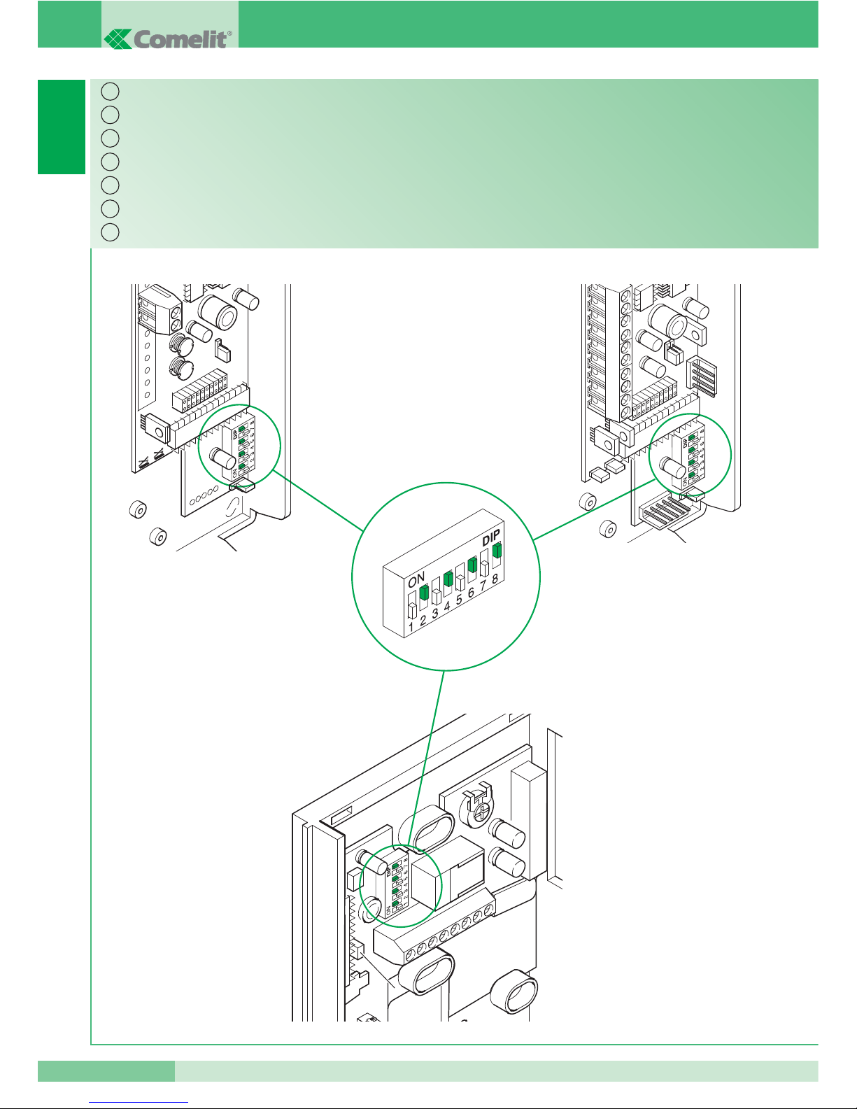
Programmering adres monitor en Style-deurtelefoon.
Programmazione indirizzo monitor e citofono Style.
Programming monitor address and Style entry phone.
Programmation adresse moniteur et interphone Style.
Programmierung Adresse von Monitor und Sprechstelle Style.
Programación de dirección monitor y telefonillo Style.
Programování monitoru nebo telefonu Style.
IT
EN
FR
NL
DE
ES
CZ
FT SB2 24
FT SB2 24
7
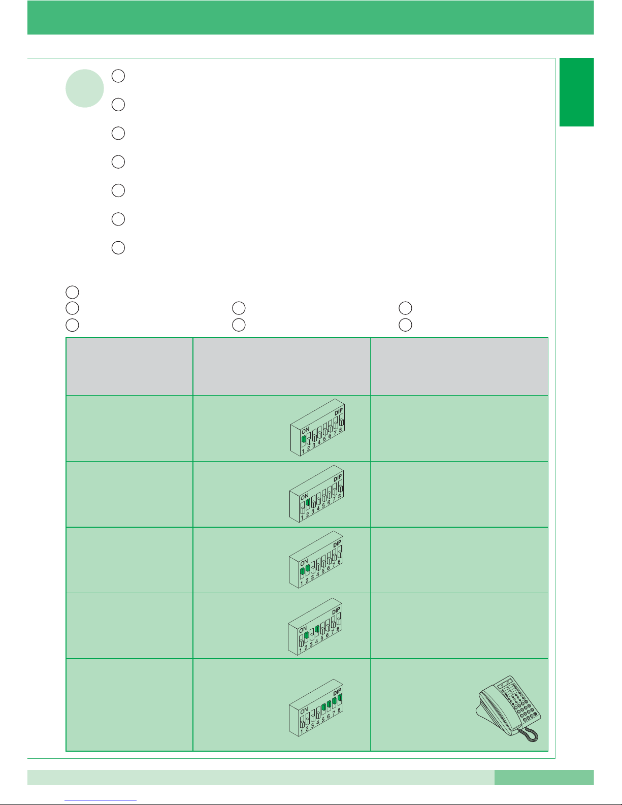
1
Voorbeld programmering
Programmerung Beispiel
Ejemplo de programacion
Príklad programování
Esempio di programmazione
Programming example
Exemple de programmation
Codice utente - User code
Usager - Gebruik
Anw. Cod. - Cód.usu.
Kód
Dip switch su ON - Dip switch to ON
Dip switch sur ON - Dipswitches op ON
Dip-Schalter auf ON - Dip switches en ON
Dip prepínac poloha ON
Nome utente - User name
Nom usager - Naam gebruiker
Name des Benutzers - Nombre usuario
Jméno úcastníka
1 1 PAUL MARTIN
2 2 JOHN SMITH
3 1, 2
.......
10 2, 4
.......
240 5, 6, 7, 8
riservato al centralino 1998/A
reserved for the switchboard 1998/A
réservé pour le standard 1998/A
gereserveerd voor de
portierscentrale 1998/A
für die Zentrale 1998/A belegt
reservado a la central
de portería 1998/A
rezervováno pro centrálu 1998/A
!
IT
EN
FR
NL
DE
ES
CZ
La codifica può avvenire in qualsiasi momento, anche senza alimentazione!
Vedi tabella di codifica completa a pag. 15.
Coding can take place at any time, even without power!
See complete code table on page 15.
Le codage peut être effectué à n’importe quel moment, même en l’absence d’alimentation!
Voir tableau de codage complet page 15.
Deze codering kan altijd worden ingesteld, ook zónder spanning op het systeem!
Zie de complete coderingstabel op blz. 15.
Die Codierung kann jederzeit erfolgen, auch ohne Stromversorgung!
Siehe komplette Codierungstabelle auf S. 15.
La codificación puede tener lugar en cualquier momento, incluso sin alimentación!
Véase la tabla de codificación completa de la pág. 15.
Programování lze provádet i bez prítomnosti napájecího napetí. Kódovací tabulka viz. str.15.
.
IT
EN
FR
NL
DE
ES
CZ
GROUP S.P.A.
8
FT SB2 24
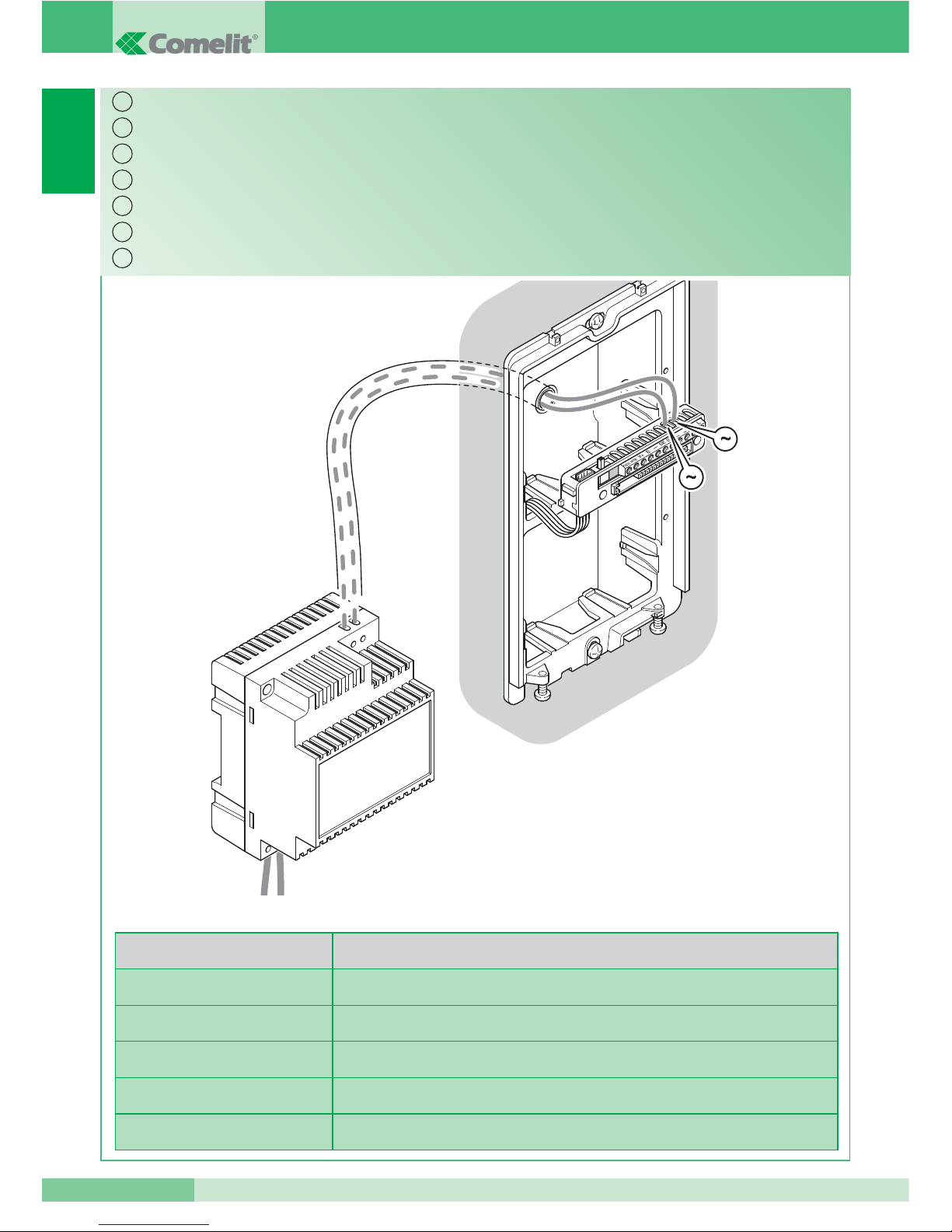
4660
1602
12 V ac
1395
230 V ac
D Max
2
D Max
0,28 mm2(Ø 0,6 mm) AWG 23 4 m (15 feet)
0,5 mm2(Ø 0,8 mm) AWG 20 10 m (35 feet)
1 mm2(Ø 1,2 mm) AWG 17 20 m (65 feet)
1,5 mm2(Ø 1,4 mm) AWG 15 30 m (100 feet)
2,5 mm2(Ø 1,8 mm) AWG 13 50 m (165 feet)
Voedingskabels van het Powercom- entreepaneel.
Cablaggio alimentazione del posto esterno Powercom.
Power supply connection for Powercom external unit.
Cablâge alimentation de la plaque de rue Powercom.
Versorgungsverkabelung der Außenstelle Powercom.
Cableado de alimentación de la unidad externa Powercom.
Napájení venkovní hovorové jednotky Powercom.
IT
EN
FR
NL
DE
ES
CZ
FT SB2 24
FT SB2 24
9
3
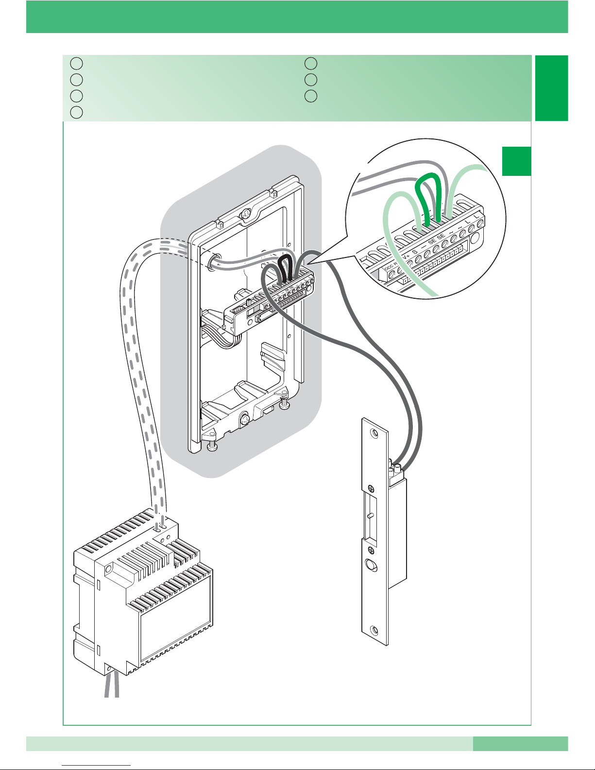
12 V ac
1395
230 V ac
12 V ac
4660
1602
3A
Slot in AC.
Serratura in AC.
AC Lock.
Gâche en C.A.
Schloss mit Wechselstrom (AC).
Cerradura en CA.
El. zámek AC.
IT
EN
FR
NL
DE
ES
CZ
GROUP S.P.A.
10
FT SB2 24
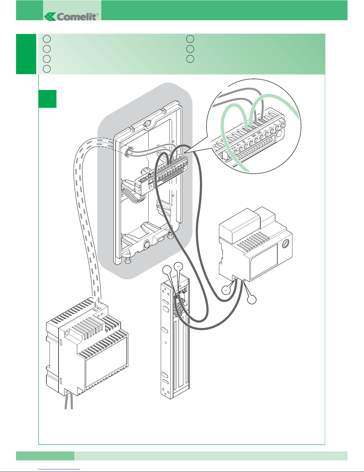
3
12 V ac
1395
230 V ac
12 V ac
12 V dc /
24 V dc
4660 nebo 1602
+
+
Slot in DC.
Serratura in DC.
DC lock.
Gâche en C.C.
Schloss mit Gleichstrom (DC).
Cerradura en CC.
El. zámek DC.
IT
EN
FR
NL
DE
ES
CZ
 Loading...